1545
Second resonance mode ensure intrinsic low coupling between elements on shielded-coaxial-cable coil designs
Sadri Güler1,2, Vitaliy Zhurbenko3, Irena Zivkovic4, Vincent Oltman Boer1, and Esben Thade Petersen1,2
1Danish Research Centre for Magnetic Resonance, Centre for Functional and Diagnostic Imaging and Research, Copenhagen University Hospital Amager and Hvidovre, Copenhagen, Denmark, 2Section for Magnetic Resonance, DTU Health Tech, Technical University of Denmark, Kgs Lyngby, Denmark, 3Department of Electrical Engineering, Technical University of Denmark, Kgs Lyngby, Denmark, 4Electrical Engineering Department, Technical University of Eindhoven, Eindhoven, Netherlands
1Danish Research Centre for Magnetic Resonance, Centre for Functional and Diagnostic Imaging and Research, Copenhagen University Hospital Amager and Hvidovre, Copenhagen, Denmark, 2Section for Magnetic Resonance, DTU Health Tech, Technical University of Denmark, Kgs Lyngby, Denmark, 3Department of Electrical Engineering, Technical University of Denmark, Kgs Lyngby, Denmark, 4Electrical Engineering Department, Technical University of Eindhoven, Eindhoven, Netherlands
Synopsis
The recent introduction of the flexible shielded-coaxial-cable coils (SCC) and their intrinsic high degree of decoupling between elements make them ideal for multichannel transceiver arrays needed for improved field homogeneity at ultra-high field MRI. In this work, we show the mode of operation of the SCC and that the selection of its second resonance mode is crucial to obtain its intrinsic high degree of decoupling between elements. We obtained this insight using both numerical simulations and an equivalent circuit model, which can guide to optimal SCC designs in the future.
Introduction
The design of radiofrequency (RF) arrays is an ongoing challenge in MRI applications with regarding sensitivity, SAR, and coupling effects between the individual coils1,2. The recently proposed shielded-coaxial-cable coils (SCC) have a flexible nature while satisfying good decoupling characteristics3 ideal for transceiver arrays. How the low coupling characteristics arise is largely unknown4,5 and a better understanding of their mode of operation and coupling characteristics is desired for optimal designs.In this work, we have investigated impedance characteristics, operation modes and coupling characteristics of SCCs designed to work at 298MHz. We present their broadband circuit representation based on the current flow of the coil model. We show that second resonance mode operation is crucial to preserve intrinsic low coupling between elements. Sweeping the distance between two SCCs clearly shows that the coupling performance is directly related to the coil’s resonance mode.
Methods
A circular SCC (HUBER+SUHNER K_02252_D) with a loop radius of 60mm was modeled in free space. The full-wave electromagnetic simulations in frequency domain (10MHz-500MHz) were performed using CST Microwave Studio.The circuit model was generated by observing the coils current flow and the loop inductance of the outermost surface is
$$L=\mu_0 a \Big(ln\big(\frac{8a}{b}\big)-2\Big)$$
where $$$\mu_0$$$ is free space permeability, $$$a$$$ is the loop radius, and $$$b$$$ is the wire radius6 while the cable’s physical dimensions are used for the coaxial cable modeling. The input impedance of the SCC is generated by the circuit model and the electromagnetic simulations.
The coupling behavior were observed by varying the center-to-center distances (0mm, 60mm, 90mm, and 125mm) between two coils.
The input impedance of the single coil is plotted to observe couplings at first and second resonance modes. The coupling coefficient between the adjacent inductors is numerically calculated on the circuit model to have similar frequency split at the first resonance mode with electromagnetic simulations.
The coil performance is compared with a conventional coil of the same loop radius with distributed capacitors.
Results
Figure 1 shows the physical model of an SCC with a capacitive matching network.Figure 2 shows the current flow on the outer gap, the broadband circuit model, and the input impedance of the SCC.
Figure 3 shows the input impedance of the SCC for various center-to-center distances.
Figure 4 shows the circuit model of two SCCs with coupling of the adjacent inductors and the input impedance of an SCC when another SCC is present and center-to-center distance is 125mm.
Figure 5 shows simulated $$$B_1^+$$$, 10gram averaged SAR $$$SAR_{10g}$$$, and $$$B_1^+/\sqrt{max(SAR_{10g})}$$$ratios of conventional loops and SCCs.
Discussion
SCCs have identical single gaps on the inner and outer conductors, which are located on opposite sides as in Fig. 1. SCCs are excited from the inner gap while the outer gap directs the current flow to the outermost surface and leads to the electromagnetic radiation.The current inside the coaxial cable obey transmission line equations and the current on the outermost surface acts as a radiator for the SCC also perceived as a loop antenna. The continuous current flow through the outer gap between the inner and outer surfaces of the outer conductor is observed in Fig. 2a. Thus, the circuit representation (Fig. 2b) is constituted with two coaxial cables and two inductors, while each corresponds to the half-length of the coil7. The coaxial cables model the inside of the cable while the inductors model the outermost surface. The connections between the elements are made with the consideration of gap locations. The impedance characteristics of the circuit model and the SCC’s electromagnetic simulations are plotted together, showing excellent agreement.
Fig. 3 emphasizes that SCCs couple at the first resonance mode while the second mode stays decoupled. At the first mode, the highest coupling is observed when the center-to-center distance is 0 mm while there is almost no coupling at 90mm (25% overlap) as expected for the coils at their first mode8. No change in input impedance observed at the second mode, clearly showing that the coil is well decoupled.
When the center-to-center distance is 125mm, adjacent SCCs transfer energy with adjacent arms. In the circuit model, this corresponds to the coupling of adjacent inductors only (Fig 4a). In Fig 4b, the agreement between the electromagnetic simulations and the circuit model is shown by numerically calculating the coupling coefficient for adjacent inductors (k=0.0525). This highlights that the coupling between SCCs takes places due to the radiation from the outermost surfaces which results in strong coupling at the first resonance mode.
Fig. 5 shows that SCCs have similar radiation characteristics and a good performance compared to conventional loops with distributed capacitors.
Conclusion
We described the mode of operation of SCCs by showing the relationships between the electromagnetics simulations and the circuit model. We also observe that the coupling at the first resonance mode takes place due to the outermost surface acting as inductive elements. At the second mode, the coils do not couple at any distance, and we show good performance compared with conventional loops which makes them outstanding candidate for 7T MRI where advanced multichannel transceiver arrays are desired for optimizing homogeneity.Acknowledgements
No acknowledgement found.References
- Fujita H. New Horizons in MR Technology: RF Coil Designs and Trends. Magn Reson Med Sci. 2007; 6(1): 29-42.
- Duyn JH. The future of ultra-high field MRI and fMRI for study of the human brain. NeuroImage. 2012; 62(2), 1241–1248.
- Ruytenberg T, Webb A, Zivkovic I. Shielded‐coaxial‐cable coils as receive and transceive array elements for 7T human MRI. Magn Reson Med. 2020; 83(3): 1135‐1146.
- Mollaei MSM, Van Leeuwen CC, Raaijmakers AJE, et al. Analysis of High Impedance Coils Both in Transmission and Reception Regimes. IEEE Access. 2020; 8: 129754–129762.
- Nohava L, Czerny R, Roat S, et al. Flexible Multi-Turn Multi-Gap Coaxial RF Coils: Design Concept and Implementation for Magnetic Resonance Imaging at 3 and 7 Tesla. IEEE Trans Med Imaging. 2021; 40(4): 1267–1278.
- Balanis CA. Antenna Theory: Analysis and Design. New York: Harper & Row, 1982.
- Libby LL. Special Aspects of Balanced Shielded Loops. Proceedings of the IRE. 1946; 34(9): 641–646.
- Roemer PB, Edelstein WA, Hayes CE, et al. The NMR phased array. Magn Reson Med. 1990; 16(2): 192–225.
Figures
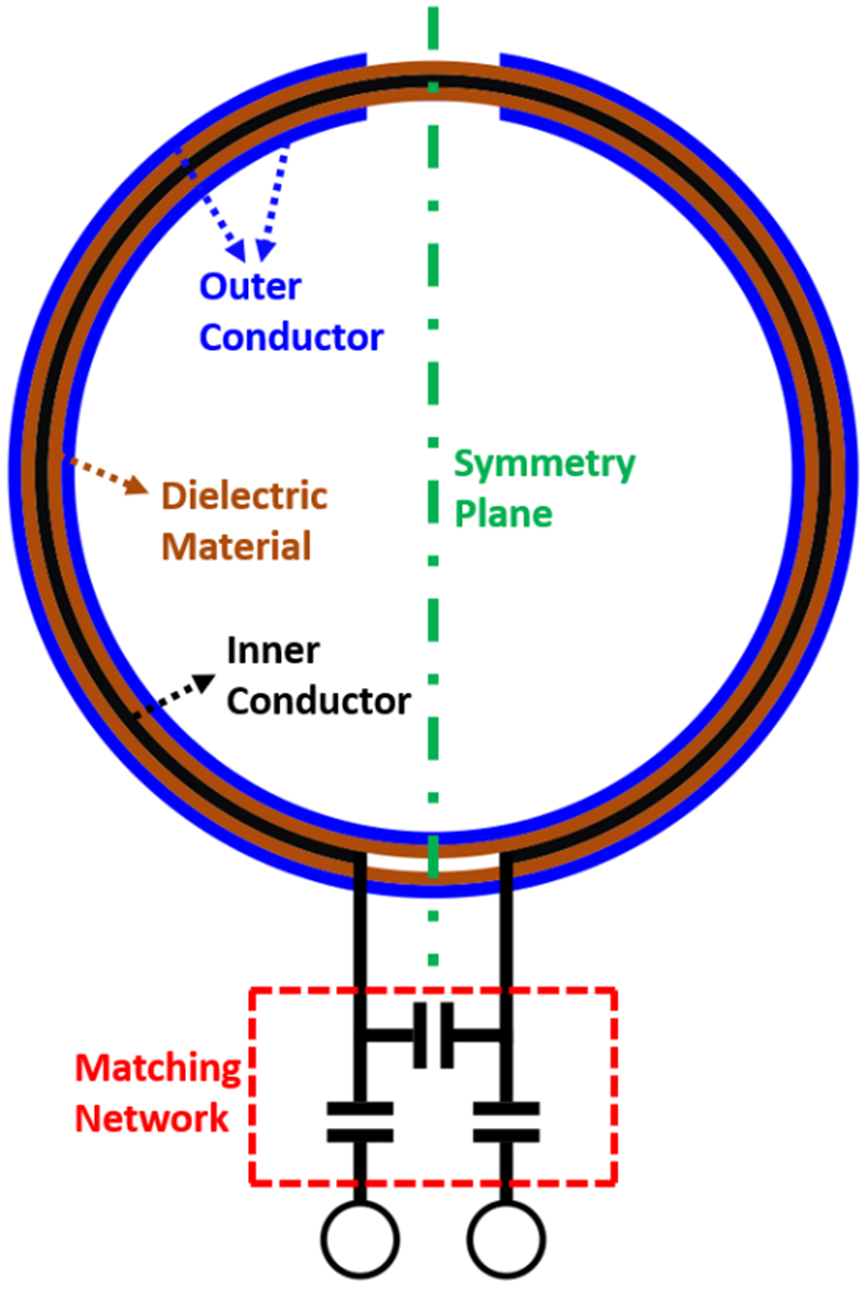
Physical model of an
SCC with a capacitive matching network.
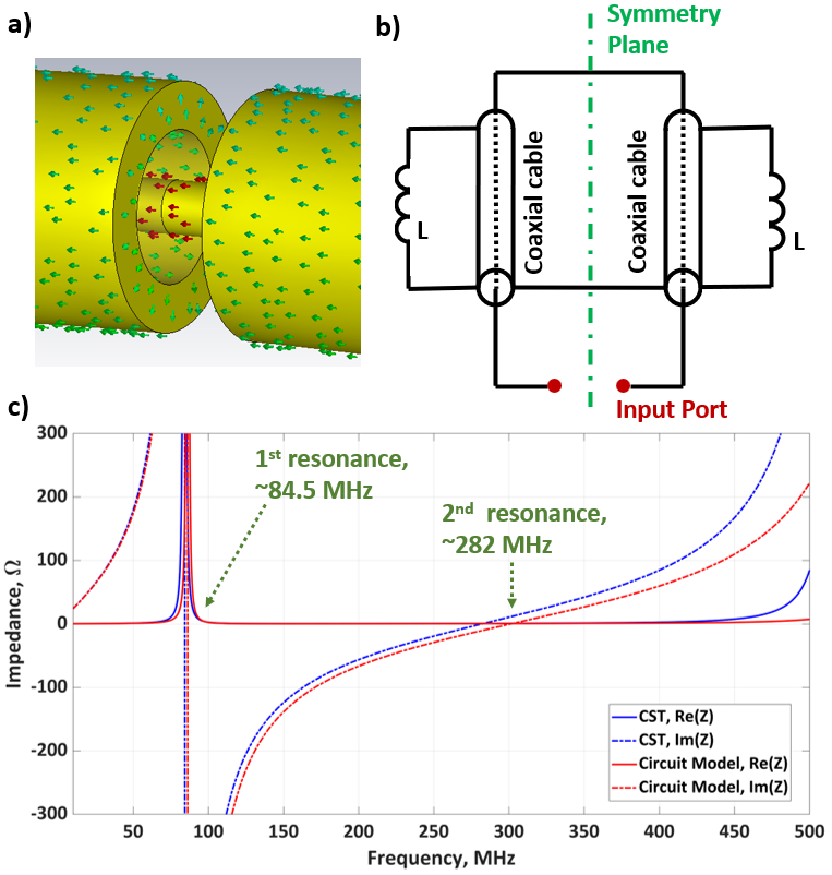
a) The current density
through the outer gap of the SCC, b) the
circuit model representation of the SCC and c) the input impedance showing
the first and second resonance of the coil with a loop radius of 60mm, both
calculated from the full-wave simulation (blue) and the circuit model (red).
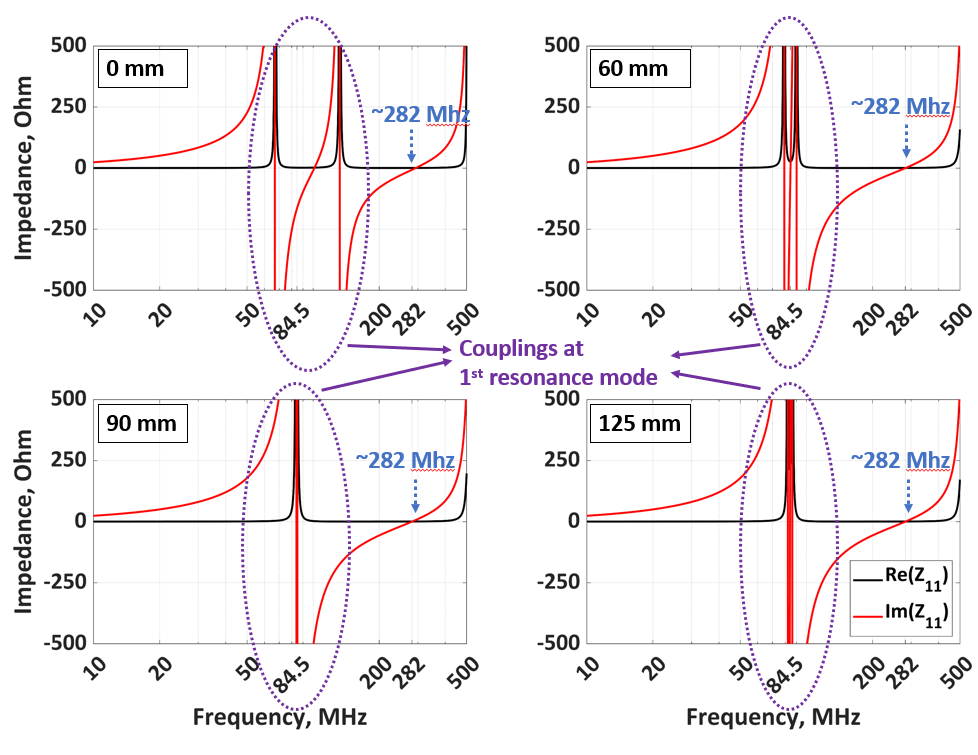
Input impedance of the SCC by the electromagnetic simulations. The
circles show the couplings at the first resonance mode at 84.5MHz while the
arrows indicate the second resonance mode at 282MHz. The second mode stays
stable while the first mode shows coupling varying by distance.
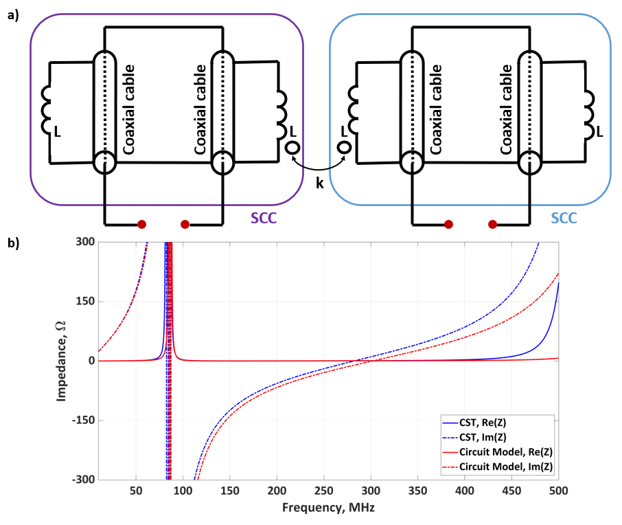
The
circuit model of two adjacent SCCs. The length of the coaxial cables and the
inductors in the circuit model correspond to the half length of the coil. The
coupling is modeled by k between the adjacent inductors for the adjacent SCCs. b)
The corresponding input impedance of SCCs calculated with electromagnetic
simulations and the circuit model.
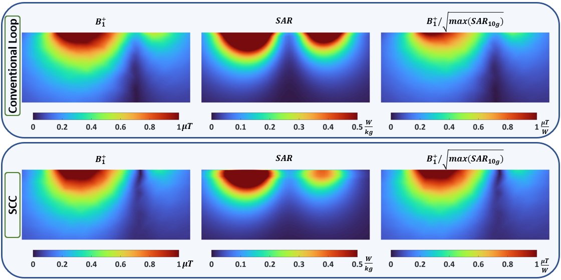
$$$B_1^+$$$ field, 10g averaged SAR ($$$SAR_{10g}$$$) and coil performance ($$$B_1^+/\sqrt{max(SAR_{10g})}$$$) distribution of conventional loops with three
distributed capacitors (first row) and SCC (second row) at the symmetry plane. $$$B_1^+$$$ and $$$SAR_{10g}$$$ are normalized with respect to 1W accepted power. The coils are placed on top of a
homogeneous rectangular box phantom ($$$\epsilon_r=50, \sigma=0.55 S/m $$$). While $$$B_1^+$$$ fields are similar, slightly less 10g averaged SAR are observed for SCCs.
DOI: https://doi.org/10.58530/2022/1545