1544
Impact of Coupling on the B1+ Field Produced by a 15-panel Tic-Tac-Toe RF Array1University of Pittsburgh, Pittsburgh, PA, United States
Synopsis
We investigated the impact of coupling (magnitude and phase) on the B1+ field distribution and intensity of a 30-channel double-rowed Tic-Tac-Toe (TTT) RF array. We found that by changing the coupling of the TTT coil modules, we are able to modify the B1+ distribution from a single channel and how the B1+ field intensity is spread between different Z levels of the 30-channel array. This effect was seen in both simulations and experimental B1+ maps.
Introduction
The 16-channel Tic-Tac-Toe (TTT) RF coil1-4, with more than 2000 in-vivo patient scans, has demonstrated the ability to excite homogeneous and load-insensitive B1+ field for 7T neuro MRI. Further improvements in homogeneity and efficiency have been seen when using smaller sized coil modules, allowing for more transmit channels and therefore more degrees of freedom with RF shimming. Most recently, we have investigated a 30-channel octagonal TTT array, which has 2 channels per panel and is partially open in the front to promote patient comfort and reduce claustrophobia. In order to optimize performance, we considered several strategies for tuning the array which have a direct impact on the coupling (S12) between array elements.Methods
The full 30-channel model consists of 15 4.25in x 4.25in TTT modules, each with 2 channels, as displayed in Figure 1. The frame and housing were 3D printed in ABS plastic, and the struts were CNC machined from Rexolite plastic. Double-sided 4 μm copper sheets were used for the shield and 8 μm copper sheets were used for the struts. Copper rods are inserted in each of the legs of the TTT struts; these, as well as tuning and matching capacitors, are used to tune the coil to 297.2 MHz. Each strut has one feeding port parallel to the Z direction (Tx 1) and one perpendicular (Tx 2). Considering the full model, we have 8 channels each in level 1 and level 2 (Tx 1 and Tx 2 from top row of panels) and 7 channels each in levels 3 and 4 (Tx 1 and Tx 2 in bottom row), as outlined in Figure 1a.To investigate the RF fields that would be produced by each channel, finite difference time domain (FDTD) simulations with transmission line and capacitor models were performed using in-house developed software. The fields from individual channels on the coil were investigated in addition to the circularly polarized (CP) combination of the channels in each Z level, incrementing the phase of each channel by 45°.
Single-channel experimental B1+ maps were acquired on a spherical saline phantom using a 7T MRI scanner (Siemens, Erlangen, Germany) and an AFI sequence with the following parameters: TR/TE = 60/3.73 ms; TA = 4 min; FA = 60°; TR ratio 0.2; 3.2mm isotropic resolution. B1+ maps for the CP Z levels were acquired using an 8-way splitter and cables with lengths corresponding to the necessary phases, using a Turbo-FLASH sequence with the following parameters: TR/TE = 2000/1.16 ms; TA = 12 min; flip angle from 0° to 90° in 18° increments; 3.2mm isotropic resolution.
Results
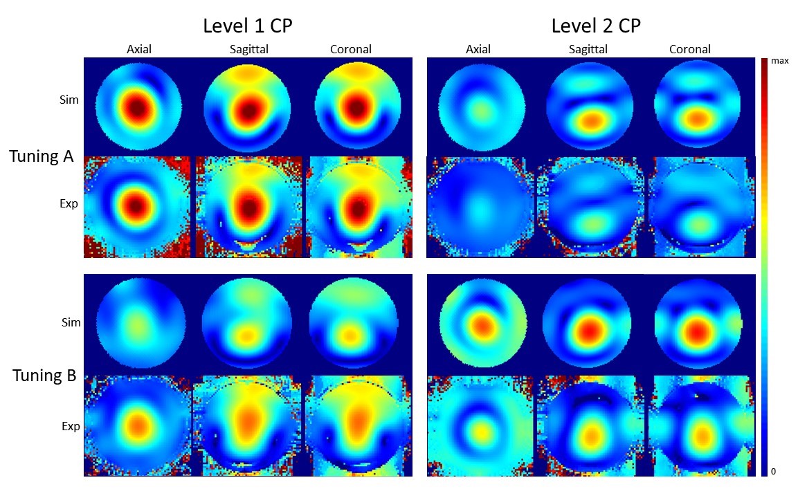
As seen in Figure 2, we were able to achieve two primary tuning methods which greatly impacted the coupling between Tx 1 and Tx 2 (S12). A representative panel was chosen from the top row of the coil. In simulation, tuning A has low coupling (S12 magnitude of -17 dB), with a drop in S12 phase of approximately 10°. Tuning B has higher coupling (S12 magnitude of -8 dB) and an S12 phase near 180°. We see similar results on the same panel experimentally, with a low-coupling tuning of -14.4 dB and a higher-coupling tuning of -11 dB with 180° phase.A comparison of B1+ from single-channel simulations and experiments is shown in Figure 3 for each of the tunings, using the same panel as Figure 2. Figure 4 displays B1+ from levels 1 and 2 combined in CP for each of the tunings, simulated and experimental. Figure 5 shows an MPRAGE image acquired on a volunteer using only level 1 and transmitting in CP, using tuning A.
Discussion
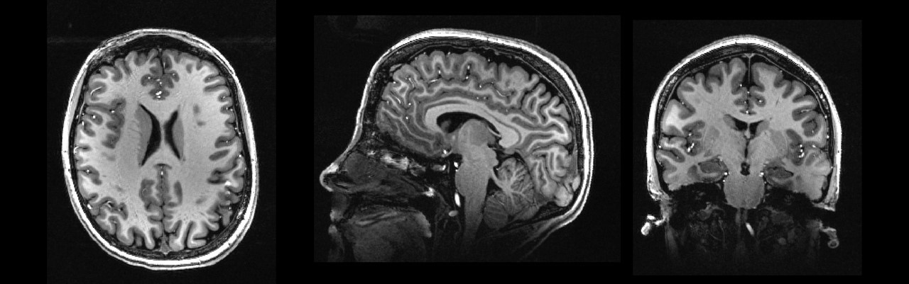
Modifying the magnitude and phase of S12 appears to impact the B1+ fields produced by each channel, even though the ports are still tuned and matched. This is seen both in the single-channel fields (Figure 3) as well as in the combined levels (Figure 4). Tuning A provides significantly higher B1+ from level 1, while tuning B shows more intensity in level 2. As seen in Figure 5, using level 1 alone provides enough B1+ to adequately image the majority of the brain.As both magnitude and phase of S12 differ in the presented tunings, further work is needed to determine which tuning is more optimized for neuroimaging at 7T. This will be impacted by the position of the array levels with respect to the human head.
Conclusion
The ability to modify the coupling and the resulting B1+ fields provides us with the flexibility to achieve more homogeneous distribution using RF shimming for 7T neuroimaging.Acknowledgements
This work was supported by the National Institutes of Health under award numbers R01MH111265, R01AG063525, T32MH119168, and by the National Science Foundation Graduate Research Fellowship under Grant No. 1747452. This work used the Extreme Science and Engineering Discovery Environment (XSEDE), which is supported by National Science Foundation grant number ACI-1548562 and was also supported in part by the University of Pittsburgh Center for Research Computing through the resources provided.References
1. Kim, J., et al. Experimental and numerical analysis of B1+ field and SAR with a new transmit array design for 7T breast MRI. J Magn Reson 2016; 269: 55-64.
2. Santini, T., et al. In-vivo and numerical analysis of the eigenmodes produced by a multi-level Tic-Tac-Toe head transmit array for 7 Tesla MRI. PLoS ONE 2018; 13(11): e0206127.
3. Krishnamurthy, N., et al. Computational and experimental evaluation of the Tic-Tac-Toe RF coil for 7 Tesla MRI. PLoS ONE 2019; 14(1): e0209663.
4. Santini, T., et al. Improved 7 Tesla Transmit Field Homogeneity with Reduced Electromagnetic Power Deposition Using Coupled Tic Tac Toe Antennas. Sci Rep 2020; 11: 3370.
Figures
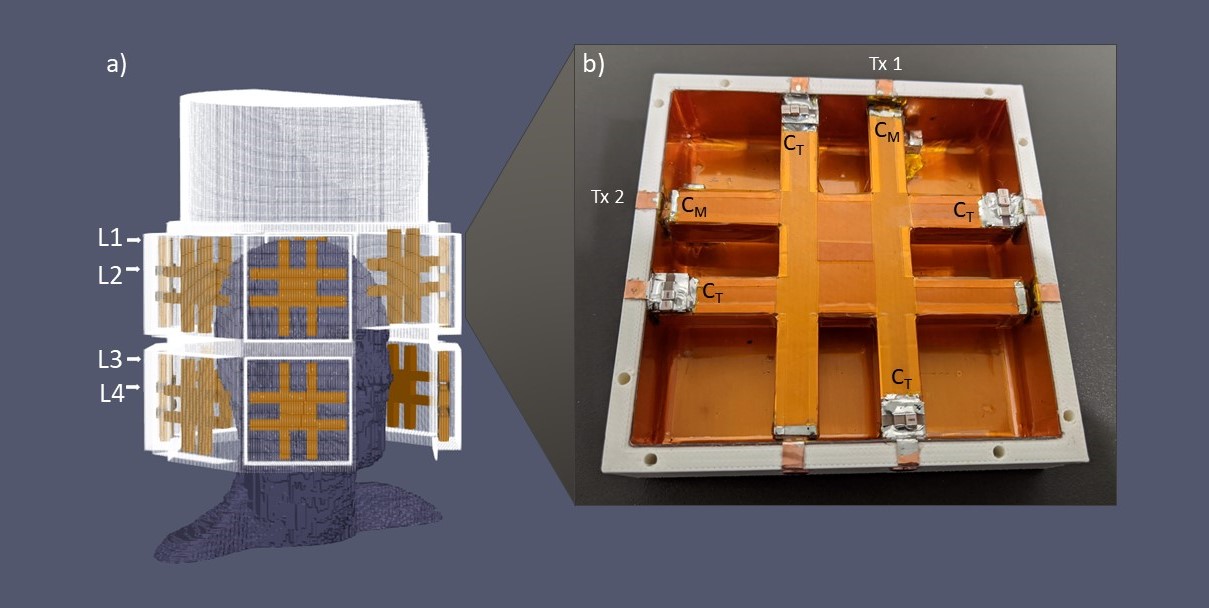
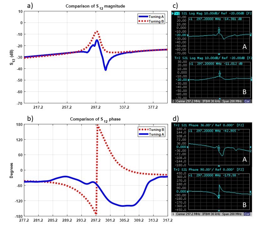
Figure 2: Comparison of simulated (a, b) and experimental (c, d) coupling (S12) - phase and magnitude - between the two ports on a single panel for both of the tuning methods (A and B).
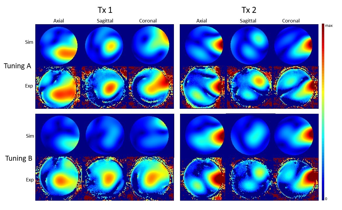
Figure 3: Simulated and experimental distributions of the B1+ fields in a spherical brain phantom produced by 2 channels in a single panel (Tx 1, Tx 2) for each tuning method (A, B).