1542
Development of 8-Channel 1H-2H Dual-Frequency loop coil array with LC tanks for 1H MRI and 2H MRS imaging of human brain at 7 Tesla1CMRR, Department of Radiology, University of Minnesota, Minneapolis, MN, United States, 2Department of Biomedical Engineering, University of Minnesota, Minneapolis, MN, United States
Synopsis
Deuterium (2H) MRS imaging (DMRSI) enables us to measure both the cerebral metabolic rate of glucose and TCA cycle rate and to image brain tumor with an excellent contrast. It is common to apply two sets of 2H and 1H RF coils for performing DMRSI, resulting in coil complexity and RF interference. We introduce an 8-channel 2H-1H dual-frequency loop coil array with LC tanks, enabling each loop coil being tuned to 2H and 1H resonant frequencies simultaneously. We have constructed a prototype head coil for human brain applications at 7 Tesla and validated the coil via benchtop and imaging tests.
Introduction
In vivo deuterium (2H) MRS imaging (DMRSI) has been applied to measure both the cerebral metabolic rate of glucose and TCA cycle rate1 and to image brain tumor and Warburg effect2,3 with excellent contrast, resolution, and sensitivity at the ultrahigh field (UHF)4,5. Additionally, machine learning-enabled high-resolution UHF DMRSI is promising to image intra-tumor heterogeneity6. From the engineering perspective of RF coil design for the DMRSI applications, it commonly requires two sets of RF coils: one for proton (1H) to acquire anatomical MRI and B0-shimming and the other for deuterium to perform DMRSI. However, this condition complicates 1H-2H coil structure and degrades coil performance because of interference among coils. Recently, we have proposed a dual-frequency coil (Figure 1) comprising a single loop coil with a bridging capacitor generating two resonant modes, which can operate at 1H and 2H Larmor frequencies7. Even with the dual-frequency coil structure, switching between 1H and 2H imaging acquisitions requires significant efforts to retune the coil. This study introduces an 8-channel 1H-2H dual-frequency loop coil array with LC tanks that enable simultaneous fine-tuning of each loop coil at both 1H and 2H resonant frequencies for whole human brain DMRSI applications at 7T.Methods
We applied LC tanks in series with the tuning and matching capacitors for 2H resonant frequency to 1H-2H dual-frequency loop coils (Figure 1 & 2). The LC tanks, which behave as open circuits at 1H resonant frequency and short circuits at the 2H resonant frequency, enabled the tuning/matching capacitors for 2H resonant frequency to independently fine-tune the coils from the tuning/matching capacitors for 1H resonant frequency. This approach ensured that 1H-2H dual-frequency loop coils could be fine-tuned to both 2H and 1H resonant frequencies simultaneously. Diplexers divided the RF inputs/outputs into 1H and 2H resonant frequencies (Figure 2). S-matrices at 297 MHz (1H) and 45.6 MHz (2H) were measured with a vector network analyzer. To test the coil performance at 1H resonant frequency, actual flip-angle images (AFI) (voxel size=3x3x3mm3) were collected to calculate 1H RF transmission B1+ fields using the method developed by Van de Moortele et al.8,9. Chemical shift images (CSI) (voxel size=2.2x2.2x2.9 cm3) at various RF pulse voltages were collected to estimate the B1+ fields by using the sinusoidal curve-fitting method to test the coil performance at the 2H resonant frequency.Results
Figure 2 represents the complete assembly of the 8-channel 1H-2H dual-frequency loop coil array including LC tanks, diplexers, and Tx/Rx switches. Figure 3A indicates that all 8 loop coils were simultaneously tuned at both 1H and 2H resonant frequencies, and Figure 3B shows the S-matrices of the coil array at 297 MHz and 45.6 MHz. Fine-tuning at 45.6 MHz did not interfere with tuning at 297 MHz. Reflection coefficients were below -12dB at 297 MHz and below -15dB at 45.6 MHz. Calculated B1+ fields from the center slices (Figure 4) in 1H AFI images demonstrate regular B1+ field and signal patterns in axial orientation which mean each coil element equivalently generated B1 field in 1H imaging. A representative 2H CSI slice (Figure 4E, acquired from a head-shaped water phantom) is overlaid with a 1H localizer in axial orientation, displaying a relatively homogenous 2H signal distribution across the entire phantom except the anterior region owing to the air bubble inside the phantom. Figure 5 shows the B1+ field from the slice near the center of the coil elements estimated with the sinusoidal curve-fitting method as well as the sinusoidal curve-fittings of representative CSI voxels for Channels 2 through 8 with 2H MRS’s near the nominal 90-degree flip angle. The results collectively indicate similar performance among all loop coils, except Channel 1 which was dysfunctional for the imaging measurement, and good coverage across the entire phantom.Discussion
From the simultaneous measurement of S-matrices at both 1H and 2H resonant frequencies, the prototype head coils successfully established the independent tuning capability at the 2H resonant frequency while avoiding interference at 1H resonant frequency. Overlapped coil structure showed sufficient decoupling capability among the adjacent coil elements. 1H B1+ fields confirmed normal distribution as anticipated. The estimated 2H B1+ field and CSI showed evenly distributed D2O signals with an excellent signal-to-noise ratio. However, the improvement in Channel 1 as well as the decoupling efficiency among coils could further boost the coil performance for human 1H MRI and DMRSI applications at 7 Tesla. In near future, distributed capacitors on the coil conductors will be added to the coil structure to evenly generate the field to homogeneously cover 3D volume for both frequencies. Also, additional broadband decoupling networks among face-to-face coil elements will be added to increase the homogeneity of the signal transmission and reception and decrease the interference among coils.Conclusion
In this study, an 8-channel 1H-2H dual-frequency coil array with LC tanks was successfully built and tested for phantom studies at 7 Tesla. Further investigations for human brain images will be performed with both 3D EM simulations with human head model and signal analysis with human head-shaped phantom, and test scans will be performed with human subjects to study energy metabolism and neuroenergetics and exploit the DMRSI applications for the human brain tumor at UHF.Acknowledgements
NIH grants of R01 CA240953, U01 EB026978, and P41 EB027061.References
1. Lu M, Zhu XH, Zhang Y, Mateescu G, Chen W. Quantitative assessment of brain glucose metabolic rates using in vivo deuterium magnetic resonance spectroscopy. J Cereb Blood Flow Metab 2017;37(11):3518-3530.
2. Lu M, Zhu XH, Zhang Y, Low W, Chen W. Simultaneous Assessment of Abnormal Glycolysis and Oxidative Metabolisms in Brain Tumor using In Vivo Deuterium 2H MRS Imaging. In: Proc Intl Soc Mag Reson Med; 2016; Singapore. p. 3962.
3. De Feyter HM et al. Deuterium metabolic imaging (DMI) for MRI-based 3D mapping of metabolism in vivo. Sci Adv 4, DOI: 10.1126/sciadv.aat7314 (2018).
4. Zhu XH, Lu M & Chen W. Quantitative imaging of brain energy metabolisms and neuroenergetics using in vivo X-nuclear 2H, 17O and 31P MRS at ultra-high field. Journal of Magnetic Resonance 292, 155-170 (2018).
5. de Graaf RA et al. On the magnetic field dependence of deuterium metabolic imaging. NMR in Biomedicine 33:e4235 (2020).
6. Li Y, Zhao Y, Guo R, Wang T, Zhang Y, Chrostek M, Low WC, Zhu XH, Liang ZP, Chen W. Machine Learning-Enabled High-Resolution Dynamic Deuterium MR Spectroscopic Imaging. IEEE Trans Med Imaging 2021;DOI: 10.1109/TMI.2021.3101149.
7. Zhang GL, Zhu W, Zhu XH, Wiesner HM, Wang T, Chen W. A dual-frequency surface coil design comprised of a single loop for both proton and deuterium magnetic resonance imaging at 16.4T. In: Proc Intl Soc Mag Reson Med (ISMRM) 2020; p. 4105.
8. Van de Moortele P., Ugurbil K. Very Fast Multi Channel B1 Calibration at High Field in the Small Flip Angle Regime. Proc Intl Soc Mag Reson Med 2009; 17: 367
9. Van de Moortele PF, Akgun C, Adriany G, Moeller S, Ritter J, Collins CM, Smith MB, Vaughan JT, Ugurbil K. B1 destructive interferences and spatial phase patterns at 7T with a head transceiver array coil. Magn Reson Med 2005; 54 (6):1503-18.
Figures
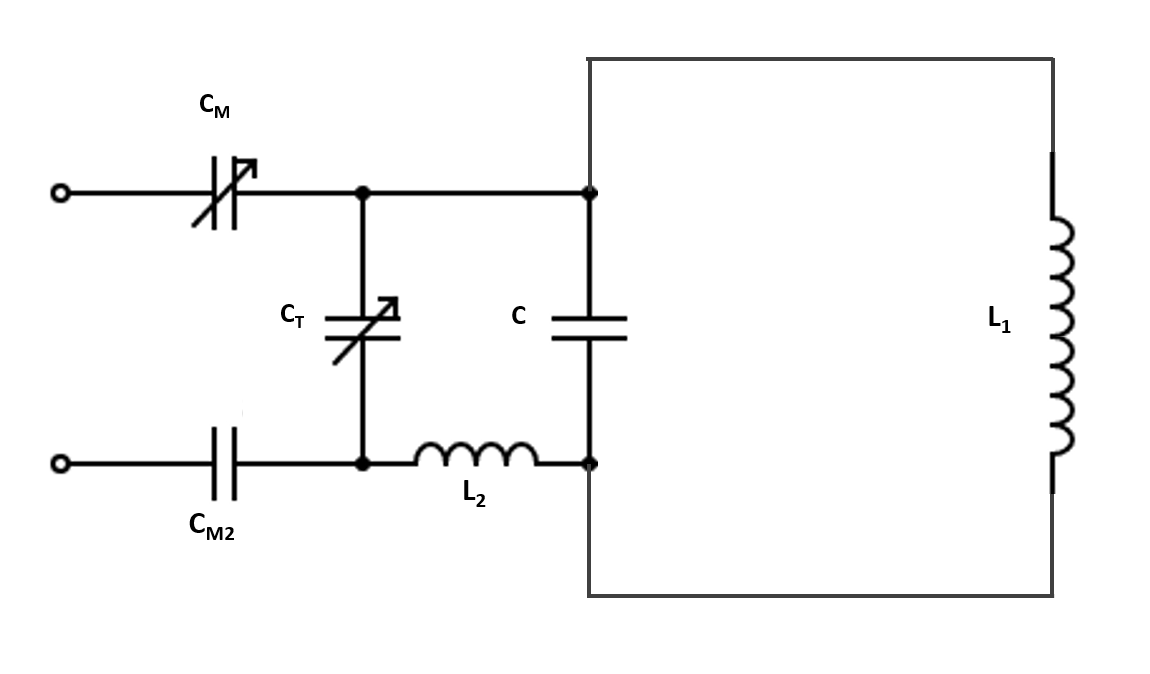
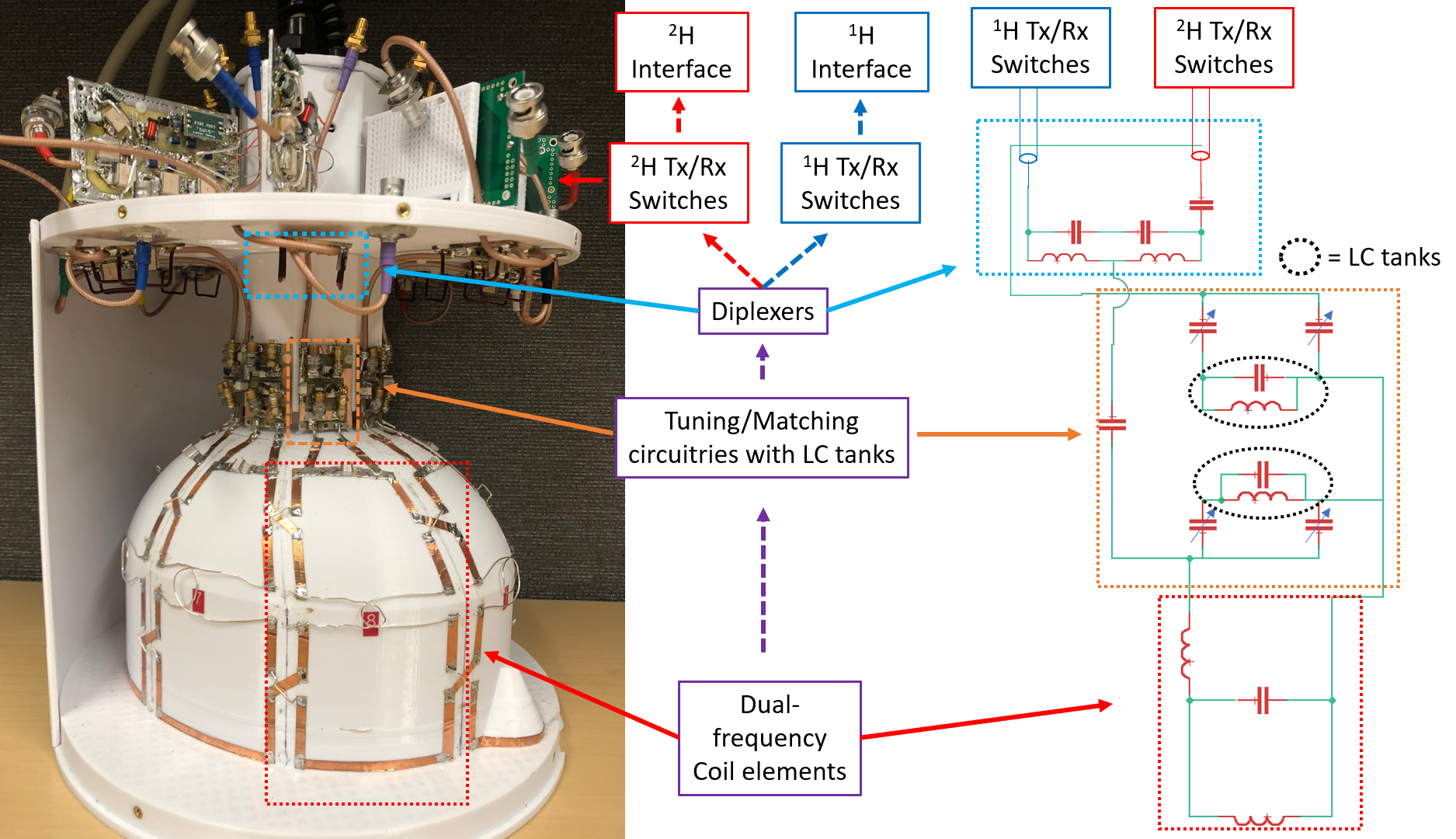
Figure 2. A photograph of the actual 8-channel 1H/2H dual-frequency coil array and a schematic of coil design from coil elements to 1H and 2H interfaces. The overlapped structure is applied to decouple broadband interference among adjacent coils. LC tank circuitry blocked the 1H frequency signal which allows fine-tuning and matching at 2H frequency without interference to the tuning and matching of 1H frequency. Diplexers divide the signal from the end of tuning circuitries into 1H frequency route and 2H frequency route to 1H TR switches and 2H TR switches.
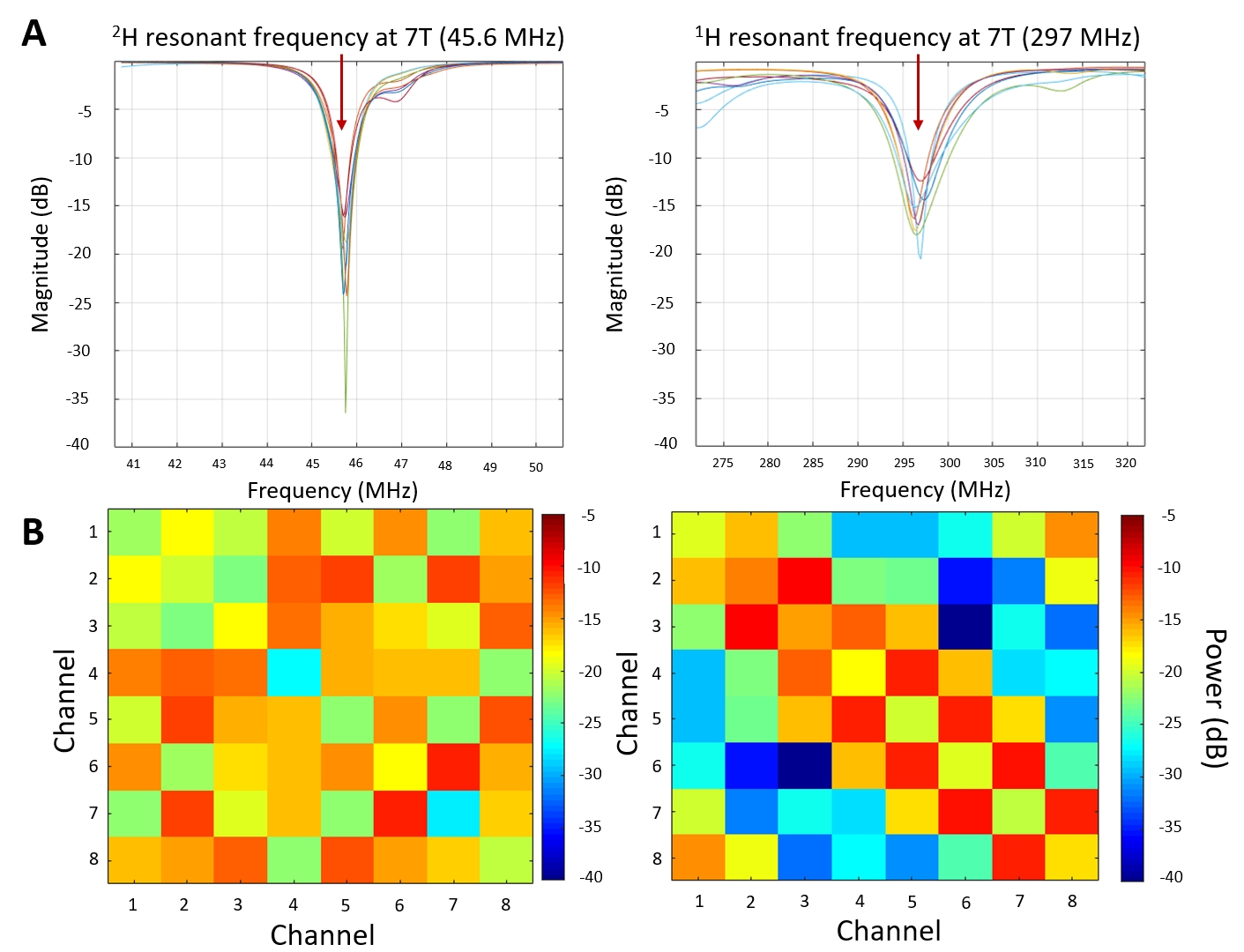
Figure 3. (A) Reflection coefficients of the dual-frequency coil array measured at the resonant frequencies of 2H and 1H. (B) The power level of S-matrices is measured at the resonant frequencies of 2H and 1H. Reflection for each channel was below -14dB at the 2H resonant frequency and below -12dB at the 1H resonant frequency. Coupling among channels at both frequencies was lower than -11dB.
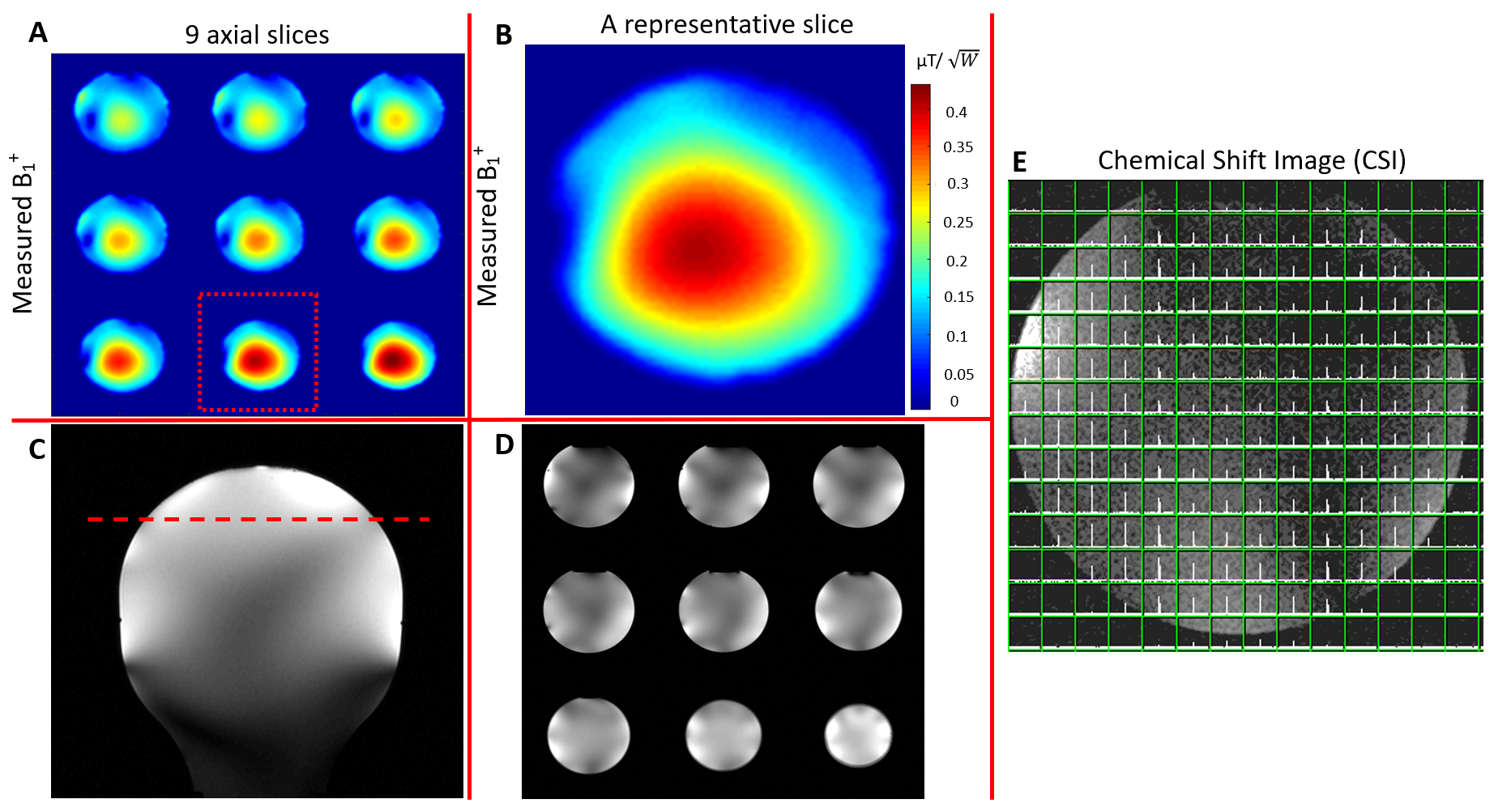
Figure 4. (A) Calculated B1+ field maps of 9 slices near the center of coil elements at 1H resonant frequency. (B) B1+ field maps of representative slices (red-dotted boxes in (A)) at 1H resonant frequency. B1+ maps were calculated by using the method by Van de Moortele8,9. (C) An SSFSE image showing the representative slice of the B1+ field map in coronal orientation. (D) 9 SSFSE images at the same position as (A). (E) 2H CSI at the center of coil elements overlaid with 1H localizer.
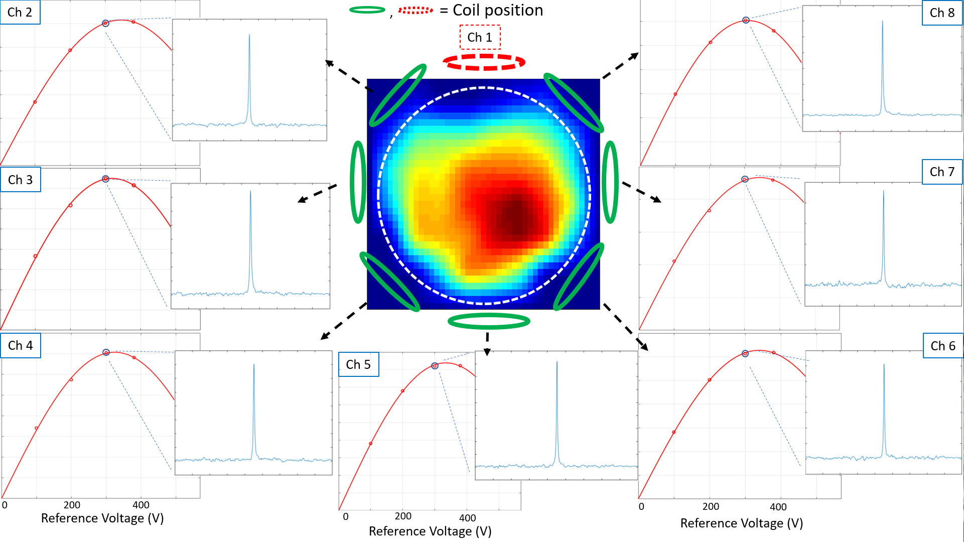
Figure 5. The combined 2H B1+ estimation using the sinusoidal curve-fitting method. Each channel showed similar reference voltage at the 90-degree flip angle. Phase-corrected spectrum at the peak voltage of each channel represented a decent signal-to-noise ratio. Channel 1 (highlighted with a red-dotted ellipse) had low signal intensity, which needs further investigations and modifications.