1541
Findings during tuning procedure of a 7T radiofrequency transmit resonator1University of Pittsburgh, Pittsburgh, PA, United States
Synopsis
In this work, we explain the tuning procedure for a new conforming Tic-Tac-Toe (TTT) array and the findings that were observed during this procedure. These findings help shape how the array can be used in building a 7 Tesla RF coil system for neuroimaging applications.. It is shown that a 2-channel and 4-channel configurations can be tuned similarly and produce similar magnetic field distribution and intensities.
Introduction
The success of the 16-channel Tic-Tac-Toe (TTT) transmit array for 7 Tesla magnetic resonance imaging (MRI) with 32-channels receive head coil is clear by the number of research clinical studies and participants scanned and the flexibility design1–6; > 2000 in-vivo patient/disease studies have been performed and 5000 more are anticipated During the development of new conformal coil7 using similar TTT designs, different resonance modes were observed. These resonance modes create different field intensities and patterns that can be exploited to achieve low specific absorption rate (SAR) levels with high transmit field homogeneity. Multiple tuning modes were simulated using the conformal TTT design as base for these tests, as it has geometric advantages when compared to the planar TTT design.Methods
Starting with the curved TTT design panel (Figure 1a-d), different tunings and modes can be achieved by changing how the panel resonates. The copper rods inside of each “leg” (Figure 1c) of the Tic-Tac-Toe strut change the length of the transmission line that it forms.. The dielectric material of which the strut is composed of can also be changed to modify the resonance frequency of the panel. Lastly, capacitors (Figure 2) can be added from the strut to the shield as another way of modifying the resonance characteristic of the panel.The tuning process was done via simulations. For each tuning configuration, a full simulation of magnetic and electric field interactions using an in-house FDTD validated software with a precise transmission line modelling was performed8. The first step was to digitally describe a physical model of transmit radiofrequency coil panel. Instead of manually describing each point of the 3D space for each different configuration, an in-house developed software was used allowing for easy creation of the correct geometry description of multiple different models by simply changing a few parameters.
Since three parameters are responsible for tuning of the panel, two were fixed at reasonable values (based on previous experience with the panel geometry in both simulation and experiment) and the third parameter was randomly changed within reasonable bounds. For this work, the capacitor values and dielectric constant of the strut were kept constant, and the rod length was randomly changed. Simulations were performed for hundreds of different configurations resulting in a variety of different tunings.
The panel can also be configured with different number of channels. A 2-channel (Figure 2a) and a 4-channel (Figure 2b) configuration were explored, and similar modes can be obtained with both configurations. For comparison of the circularly polarized magnetic field (B1+) intensities9 between the different channel configurations, channel 1 of the 2-channel panel was compared to the sum of channel 1 and channel 3 of the 4-channel panel using half of the original amplitude and adding a 180-degree phase between the channels.
Results
During the tuning process of a 2-channel TTT curved panel, different reflection coefficients (S11) were observed (Figure 3). Three different modes can be seen by selecting specific combination of the rods in the panel. These findings are present in both channel 1 (Figure 3a) and channel 2 (Figure 3b) of the 2-channel panel.Another tuning combination can produce a similar reflection coefficient between the 2-channel panel (Figure 3c) and a 4-channel panel (Figure 3d). The B1+ field intensity matches between the 2-channel configuration (Figure 4a) and the 4-channel configuration (Figure 4b). The difference between the two intensities (Figure 4c) is 25% lower than the max amplitude of either.
Discussion & Conclusion
The conformal TTT design allows for a great flexibility on the design of radiofrequency transmit arrays for 7 Tesla MRI. This flexibility can be explored with RF shimming methods10,11 for optimization of the homogeneity and SAR values obtained from the array. The TTT curved panel has its intrinsic modes that can be tuned independently of the number of transmit channels used on the coil. The difference in signal amplitude for different channel configurations is minimal (up 25% of the max amplitude) and can be explained by slightly different tuning. Therefore, the use of 2-channels instead of 4-channels comes down to reducing the complexity and loses introduced by the increased the number of channels on the panel.Acknowledgements
This work was supported by NIH R01MH111265 and R01AG063525. The author Tiago Martins was partially supported by the CAPES Foundation, Ministry of Education of Brazil, 88881.128222/2016-01. This research was also supported in part by the University of Pittsburgh Center for Research Computing (CRC) through the resources provided.
References
1. Ibrahim TS, Krishnamurthy N, Wood S, Raval S, Kim H. 20-To-8 channel Tx array with 32-channel adjustable receive-only insert for 7T head imaging. In: The 21st International Society of Magnetic Resonance in Medicine Annual Meeting. ; 2013.
2. Ibrahim TS, Hue YK, Boada FE, Gilbert R. Tic Tac Toe: Highly-Coupled, Load Insensitive Tx/Rx Array and a Quadrature Coil Without Lumped Capacitors. In: Vol 16th. ; 2008:438.
3. Kim J, Krishnamurthy N, Santini T, et al. Experimental and numerical analysis of B1+ field and SAR with a new transmit array design for 7T breast MRI. J Magn Reson. 2016;269:55-64. doi:10.1016/j.jmr.2016.04.012
4. Raval SB, Santini T, Wood S, Krishnamurthy N, Zhao T, Ibrahim TS. In-vivo (8x4) 32-ch Tx-only Body Array for UHF MRI. In: International Society for Magnetic Resonance in Medicine. Vol 25th. ; 2017:3.
5. Santini T, Kim J, Wood S, et al. A new RF transmit coil for foot and ankle imaging at 7T MRI. Magn Reson Imaging. 2018;45:1-6. doi:10.1016/j.mri.2017.09.005
6. Tales Santini, Narayanan Krishnamurthy, Sossena Wood, et al. 64-channel Double-Octagon Tx Head Coil for 7T Imaging. In: International Society for Magnetic Resonance in Medicine. Vol 25th. ; 2017.
7. Martins T, Santini T, Berardinelli J, DeFranco A, Ibrahim TS. Conformal design of radio-frequency head coil for ultra-high field MRI. In: International Society for Magnetic Resonance in Medicine. ; 2021.
8. Ibrahim TS, Kangarlu A, Chakeress DW. Design and performance issues of RF coils utilized in ultra high field MRI: experimental and numerical evaluations. IEEE Trans Biomed Eng. 2005;52(7):1278-1284. doi:10.1109/TBME.2005.847564
9. Ibrahim TS. Analytical approach to the MR signal. Magn Reson Med. 2005;54(3):677-682. doi:10.1002/mrm.20600
10. Ibrahim TS, Hue YK, Tang L. Understanding and manipulating the RF fields at high field MRI. NMR Biomed. 2009;22(9):927-936. doi:10.1002/nbm.1406
11. Tang L, Hue YK, Ibrahim TS. Studies of RF Shimming Techniques with Minimization of RF Power Deposition and Their Associated Temperature Changes. Concepts Magn Reson Part B Magn Reson Eng. 2011;39B(1):11-25. doi:10.1002/cmr.b.20185
Figures
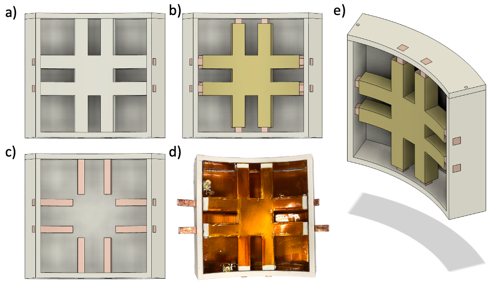
Figure 1: Computer model of the conformal TTT panel (a-c) and photo of the implemented panel (d). a) model of the panel showing the dielectric material of the strut. b) model of the panel showing the conductive part of the strut. c) model of the panel showing the rods that go inside the strut. e) model of the panel showing the curvature of the panel.
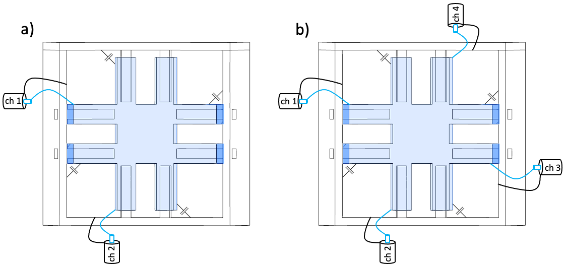
Figure 2: Drawing of the connection of channels in the panel using a) 2-channel configuration and b) 4-channel configuration. The transmission line is connected to the strut and the shield for each channel.
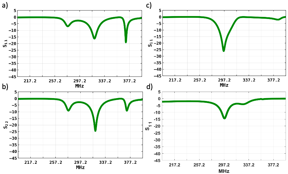
Figure 3: Plot of the reflection coefficient for an arbitrary tuning configuration showing the three different modes of the panel for a) channel 1 and b) channel 2 of the 2-channel panel configuration. Also, a different tuning mode with similar reflection coefficient between the c) 2-channel and the d) 4-channel panel configurations.
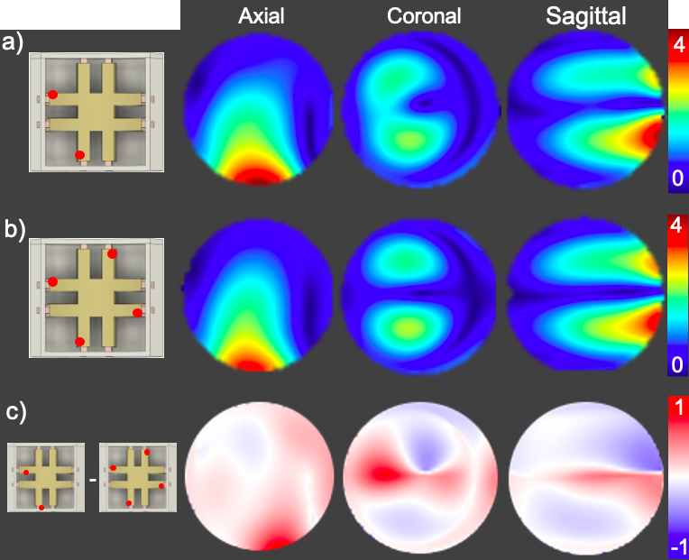
Figure 4: Magnetic field intensities and distribution for a) channel 1 of the 2-channel panel and b) the combination of channel 1 and 3 for the 4-channel panel. The difference between the two configurations is shown in (c).