1537
On the Noise Correlation in Receive Phased Arrays1Multiwave Imaging SAS, Marseille, France, 2Université Paris-Saclay, CEA, CNRS, BAOBAB, NeuroSpin, Gif-sur-Yvette, France, 3Université Paris-Saclay, CEA, IRFU, DACM, Gif-sur-Yvette, France
Synopsis
The noise covariance matrix is useful for SNR and g-map computation and, with the noise correlation matrix, commonly taken as metrics to characterize decoupling of denser and denser receive arrays. Roemer provided a resistance matrix accounting for noise correlation. In the literature, Bosma defined the noise covariance matrix from the scattering matrix, easing predictions based on electromagnetic simulations or VNA measurements. Here noise correlation is analyzed for 50 Ω power-matched and low-input impedance preamplifiers. As predicted by Bosma, strong coupling does not necessarily imply a high noise correlation, which also depends on the ports impedance matching.
Introduction
Noise covariance and noise correlation matrices are commonly taken as metrics to assess quality of coil decoupling. The noise covariance matrix is important for SNR and g-maps computation and therefore to predict parallel imaging performance of a receive array[1]. In the literature, two models are used to compute this matrix: Roemer’s R matrix[2], $$$R_{i,k}\equiv\sigma\int E_i(\vec{r})\cdot E_k^*(\vec{r})dV$$$ and Bosma's formula[3-5] : $$$\newcommand\dag\dagger C_S=kTB(I-SS^\dag)$$$, S being the scattering matrix of the multiport array. Analysis of the Bosma's equation shows that, if the S matrix has zero values on its off-diagonal elements (perfect decoupling), the noise covariance matrix Cs is diagonal, implying no noise correlation between the channels. Also, Cs is diagonal if the diagonal elements of the S matrix are zero-valued (perfect matching). Therefore, we investigate the validity of this formula for power-matched and preamplifier-decoupled coils with a basic setup and clinical receive arrays at 7T.Methods
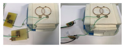
First, the noise correlation from two identical 5cm-diameter loops (Fig.1) was compared using 50Ω power-matched preamplifiers and low-input impedance preamplifiers (WanTcom) in two loop arrangements: optimal overlapping minimizing mutual inductance and non-overlapping loops separated by 0.5 cm. Loops were placed 2.5 cm above an agar phantom (εr=72, σ=0.78 S/m). In a 7T scanner, 500k noise samples were acquired for all four configurations (50 Ω and low input impedance preamplifiers in the two loop arrangements). We used 50Ω-input impedance and low-input impedance (1.5 Ω) commercial preamplifiers with the usual preamp-decoupling implementation[6]. Optimal noise figure for both systems requires a 50 Ω impedance seen from the preamplifier input, thereby easing the tests as preamplifiers can be exchanged without further modifications. Preamplifier decoupling provided an isolation of -15 dB when using two small probes[6].Second, the noise correlation was measured for an homemade 32-channel array, so-called “Avanti2” using neither preamplifier decoupling nor overlapping. All elements are tuned and matched to 50 Ω and connected to 50Ω-input impedance preamplifiers, the receive system being therefore power-matched. Its noise correlation matrix, measured at the scanner, is compared to that of the commercial Nova coil (8Tx/32Rx, Nova Medical, Wilmington, USA), using loop overlapping[7] and supposedly preamplifier decoupling. Both coils are loaded with a spherical agar phantom (εr=72, σ=0.78 S/m, 15cm diameter).
Both experiments were performed on a Siemens Magnetom at 7 T and noise covariance matrices were transformed into noise correlation matrices.
Results and Discussion
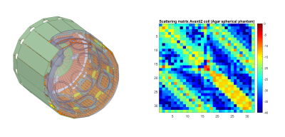
For overlapped loops (S21 = -16 dB, S11 and S22 = -18 dB), the noise correlation (off-diagonal element of the noise correlation matrix, obtained from the covariance matrix) measured from the 50Ω-preamplifier case is 0.066±0.001 (Fig.2). On the other hand, when using preamplifier decoupling, the noise correlation between the two loops is 0.183±0.001. Therefore, a 2.8 times higher correlation is found when using preamplifier decoupling for two overlapped loops. For 0.5 cm separated loops (S21=-6.5 dB, S11 and S22=-13dB), measured correlation was 0.075±0.001 for 50Ω-input preamplifiers and 0.055±0.002 for preamplifier decoupling. By measuring S parameters with a network analyser (50Ω input impedance), the correlation with Bosma's formula was found to be 0.042 for well-overlapped loops and 0.113 when separated by 0.5cm. Interestingly, by changing the reference impedance[9] from 50 Ω to 1.5 Ω (input impedance of WanTcom preamplifiers) the noise correlation becomes 0.201 for overlapped loops and 0.026 when separated from 0.5 cm. The slight difference between in-lab and scanner measurements can be explained by the resonance frequency shift when placing the system inside the MRI tunnel, thus changing the measured S matrix, as well as by the remaining correlation between the downstream Siemens amplifiers in the scanner.The simulated scattering matrix (Fig.3) for Avanti2 coil exhibits a relatively strong remaining coupling with values ranging from -6 to -15 dB for nearest neighbours. Yet, a better noise correlation matrix was found when compared to the Nova coil (Fig.4). The mean correlation for the Nova coil is 0.0585 and has a maximum value of 0.459 whereas Avanti2 coil exhibits a mean 0.039 and a maximum 0.277 correlation. The Nova correlation matrix indicates that overlapping loops have a much higher correlation compared to the nearest neighbours in the Avanti2 coil. This is in good agreement with the first experiment.
Presented results indicate that one can obtain low noise correlation even in the case of strong remaining coupling. When using preamplifier decoupling, the system becomes unmatched (50 Ω presented to the 1.5 Ω preamplifier input), the diagonal terms of the S matrix are thus high and, according to Bosma's formula, correlation may drastically increase, especially for overlapping coils. The phase shift of the individual complex elements in the S matrix has an important impact on the measured noise correlation. Therefore, specific attention on the S matrix should be given when combining overlapping and preamplifier decoupling to mitigate noise correlation.
Conclusion
Bosma's noise covariance formula was analysed to determine the possible ways to decrease noise correlation for receive phased arrays. A homemade 32-channel coil was built without preamplifier decoupling nor overlapping and showed lower noise correlation than the commercial Nova coil. We showed that there is no simple relation between coupling and noise correlation. The overall impact of the noise covariance matrix and the comparison of parallel imaging performance between power-matched and preamplifier-decoupled coils are currently studied.Acknowledgements
These research activities have received funding from the European Union's Horizon 2020 research and innovation programme under grant agreement No 952106 (M-ONE project); and the Leducq Foundation (large equipment ERPT program, NEUROVASC7T project) for scanner acquisitions.References
1) Pruessmann et al. – SENSE Sensitivity encoding for fast MRI - Magnetic Resonance in Medicine 42:952–962 (1999)
2) Roemer, P.B., Edelstein, W.A., Hayes, C.E., Souza, S.P. and Mueller, O.M. (1990), The NMR phased array. Magn Reson Med, 16: 192-22
3) S.W. Wedge, D.B. Rutledge, Noise Waves and Passive Linear Multiports, IEEE Microwave and guided wave letters. Vol.1 No.5 May 1991
4) Bosma, H. (1967). On the theory of linear noisy systems. Technische Hogeschool Eindhoven. https://doi.org/10.6100/IR109175
5) C. Findeklee, Array Noise Matching via the Scattering Matrix, IEEE Transactions on Antennas and Propagation, Vol. 67, No. 4, April 2019
6) Fujita H, Zheng T, Yang X, Finnerty MJ, Handa S. RF surface receive array coils: the art of an LC circuit. J Magn Reson Imaging. 2013 Jul;38(1):12-25
7) Nova Medical Operator Handbook, 7T Head transmit coil with 32 channel array
8) Avdievich N, et al. Resonant Inductive Decoupling (RID) for Transceiver Arrays to Compensate for both Reactive and Resistive Components of the Mutual Impedance. NMR Biomed; 26(11):1547-54, 2013.
9) R.B. Marks, D.F Williams, A General Waveguide Circuit Theory, J. Res. Nat. Inst. Stand. Technol. 97, 533 (1992)
Figures


