1447
An 8-channel transmit 64-channel receive compact head coil for Next Gen 7T scanner with head gradient insert1Imaging Centre of Excellence, University of Glasgow, Glasgow, United Kingdom, 2MR CoilTech Limited, Glasgow, United Kingdom, 3Helen Wills Neuroscience Institute, University of California, Berkeley, Berkeley, CA, United States
Synopsis
The NextGen 7T scanner is equipped with a high-performance head gradient insert and hence the radial space available on the patient table for radiofrequency (RF) coils is limited. In addition to a large visual field to support fMRI studies, a split-top receive array on a sliding mechanism is desirable for improved patient comfort. We have developed a novel 8-channel transmit 64-channel receive 7T head coil and implemented a sliding mechanism to operate within the limited space in the head gradient insert. In this abstract, we present the overall coil design, transmit array performance and preliminary phantom results.
Introduction
High-density 7T receive arrays will improve the cortical signal-to-noise-ratio (SNR) without compromising the central SNR. In addition, significant gains in parallel imaging performance can be achieved by using high-density receive arrays1-3. The NextGen 7T scanner4 is specifically built for high-resolution brain imaging. It is equipped with 128-receive channels, 16-transmit channels and a head gradient insert (“Impulse”) with Gmax 200 mT/m and slew rate 900 T/m/s.RF coils for scanners with head gradient inserts are constrained by the limited space available on the patient table. For improved patient comfort and ease of positioning the patient, a split-top receive array with sliding mechanism is desirable. This work presents the design of a compact 8-channel transmit and a split-top 64-channel receive array which operates within the space constraints of the head gradient insert.
Methods
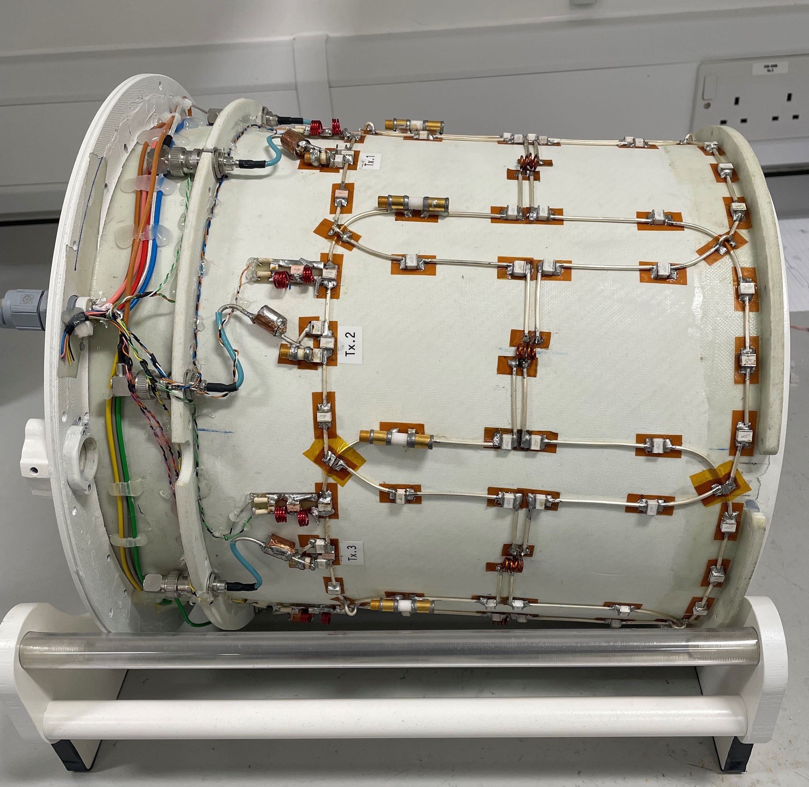
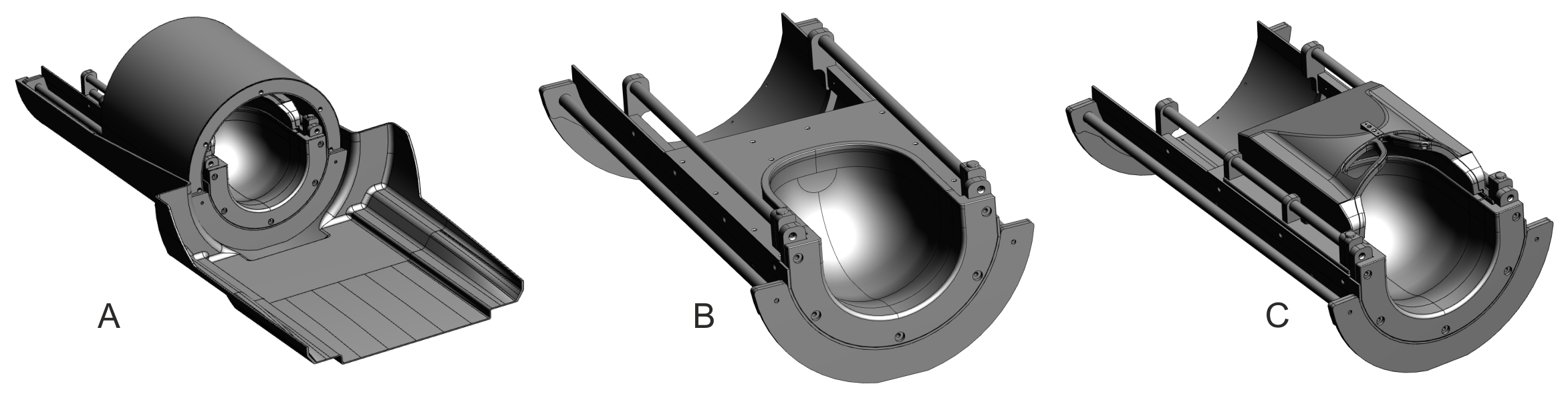
Transmit array: The transmit array consists of an 8-channel loop array constructed on a fiberglass tube of 290 mm inner diameter and extended 20 cm along the z-direction. The outer tube, at 30 mm from the coil, consisted of a slotted double layered RF shield. Each loop consisted of 13 fixed and one variable capacitor. All adjacent elements were overlapped to minimize coupling. The coupling between the second neighboring elements was reduced by counter-wound inductors5. Coil tune, match and decoupling were adjusted while the coil was loaded with a head and shoulder phantom6. A picture of the constructed transmit array is shown in figure 1.Sliding mechanism: The transmit array slides on two long fiberglass rods positioned between the inner and outer tubes and connected between the two end plates of the coil structure (Figure 2a). The sliding rods are surrounded by another tube between the two ends of the transmit array and this prevents any fluids from entering inside the array electronics. The posterior half of the receive array is fixed on to the coil structure (Figure 2b). The anterior half slides on two other rods as shown in figure 2c.
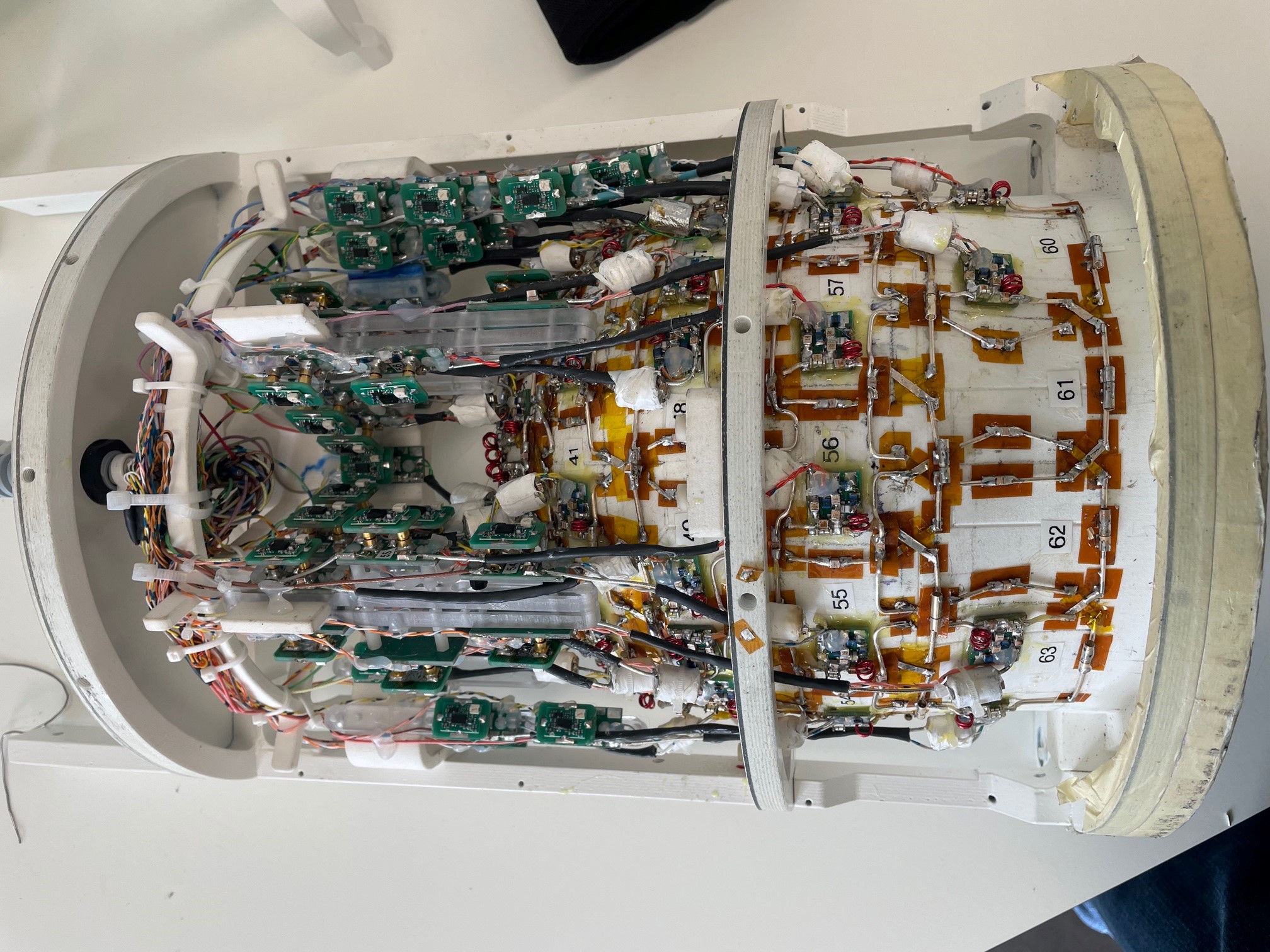
Receive array: The receive array consists of 64 rectangular loops arranged in columns. This allowed to create an overlap between the anterior and posterior half of the receive array and decouple the adjacent elements between each half. There are 40 elements on the posterior half (fig. 3) and 24 elements on the anterior half. All adjacent elements were geometrically overlapped. Each loop consisted of one variable and three fixed capacitors (ATC 100B series) and connected to a low impedance preamplifier (Wantcom Inc, MN, USA). A shielded cable trap is connected between the coil input and the preamplifier. The equivalent circuit of the receive array element is as per Ref.6. The internal dimensions of the receive helmet is 178mm along the L/R direction and 215mm along the A/P direction.
Results
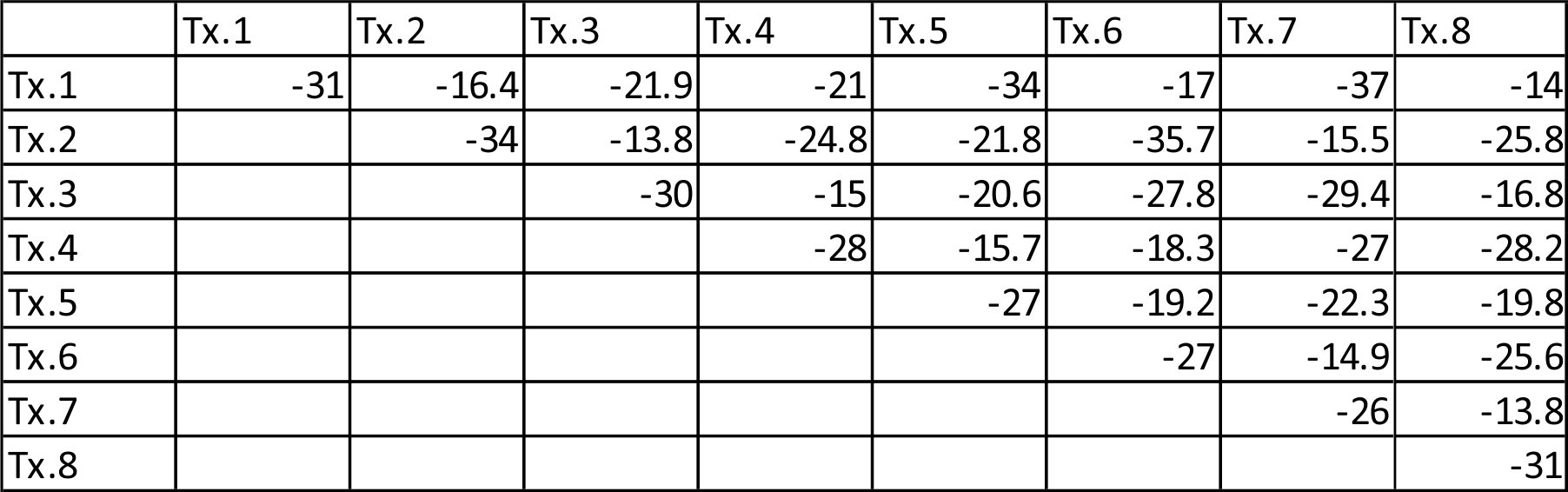
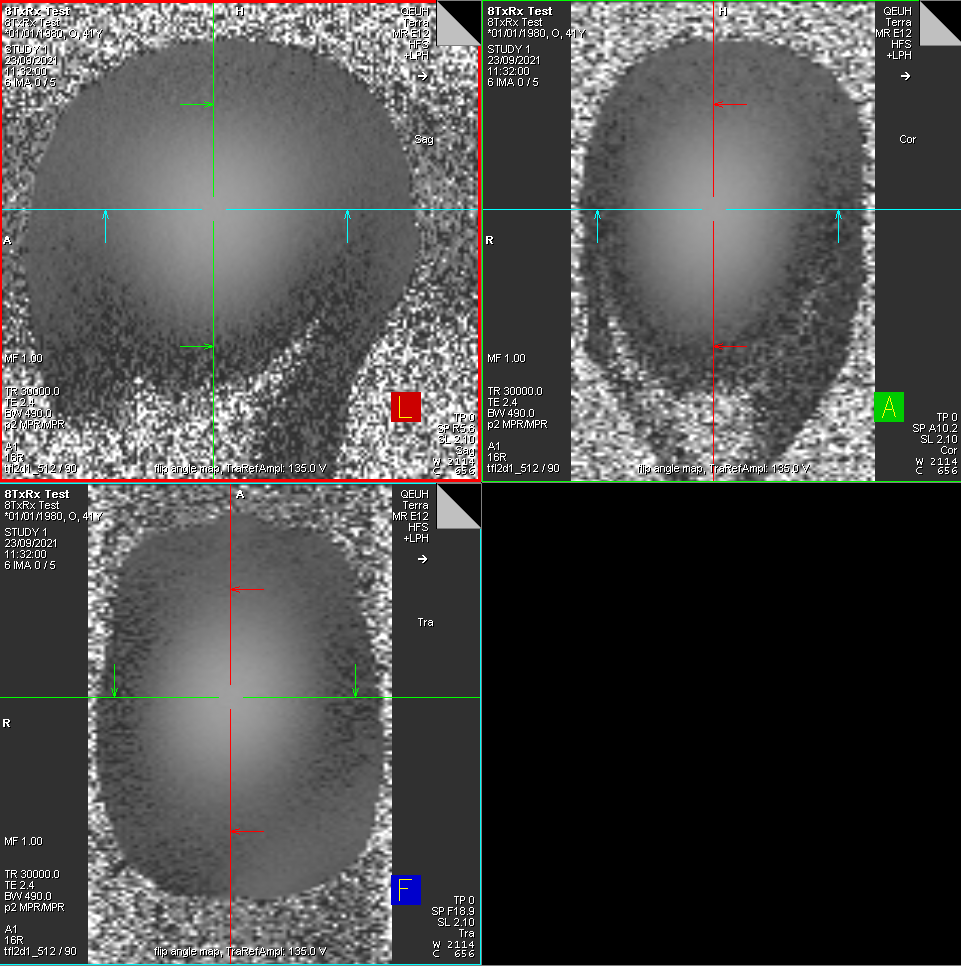
The s-parameter matrix of the transmit array is shown in figure 4. All channels were matched to better than -25dB. The average adjacent element decoupling was -15.35dB and the average next neighbor decoupling was -24.54dB. Figure 5 shows the B1+ map of the transmit array in transceiver mode acquired by driving the coil in the circularly polarized (CP) phase configuration. For this measurement, a custom built 1x8 splitter with CP phase offsets was used to drive the coil and an external TR switch module was used to receive the signal. A reference voltage of 135v was required to achieve 90° flip angle in the center of the head and shoulder phantom. This included the losses introduced by the TR switch and power splitter.The decoupling between the adjacent elements of the receive array was -12dB on average. Active detuning was better than -30dB and the average preamplifier decoupling is -20dB. Imaging results of the combined 8-channel transmit 64-channel receive is expected soon.
Conclusion
A novel 8-channel transmit array in combination with a 64-channel receive array has been developed to operate within the space constraints of the Impulse head gradient insert. The implemented sliding mechanism offers improved patient comfort. The transmit performance of the coil is evaluated using S-parameter measurements and B1+ measurements in the scanner. Future work will include imaging performance evaluation of the 64-channel array with the industry standard 32-channel head coil and custom-built 96-channel receive array7.Acknowledgements
No acknowledgement found.References
1. Ugurbil K, Auerbach E, Moeller S, et al. Brain imaging with improved acceleration and SNR at 7 Tesla obtained with 64‐channel receive array. Magn Reson Med. 2019;82:495–509
2. Mareyam A, Kirsch JE, Chang y et al., A 64-channel 7T array coil for accelerated brain MRI, ISMRM 2020, p764.
3. Wiesinger F, Boesiger P, Pruessman KP. Electrodynamics and unlitmate SNR in parallel MR imaging. Magn Reson Med 2004;52:376-390
4. Feinberg DA, Dietz P, Lie C et al., Design and Development of a Next-Generation 7T human brain scanner with high-performance gradient coil and dense RF arrays, ISMRM 202, p562
5. Williams SN, Allwood-Spiers S, McElhinney P et al., A nested eight-channel transmit array with open-face concept for human brain imaging at 7 Tesla., https://doi.org/10.3389/fphy.2021.701330
6. Shajan G, Kozlov M, Hoffmann J et al., A 16-Channel Dual-Row Transmit Array in Combination With a 31-Element Receive Array for Human Brain Imaging at 9.4 T. Magn Reson Med (2014) 71(2):870–9.
7. Shajan G, Mueller R, McElhinney P et al., A 16-channel transmit 96-channel receive head coil for NexGen 7T scanner, ISMRM 2021, p 182.
Figures