1446
Negligible loss in double tuning when stacking 1H to 31P dipoles in an 8-channel dipole array with 24 receivers at 7T1University of Cambridge, Cambridge, United Kingdom, 2Radiology, UMC Utrecht, Utrecht, Netherlands, 3Tesla Dynamic Coils, Zaltbommel, Netherlands, 4UMC Utrecht, Utrecht, Netherlands, 5Biomedical engineering, Eindhoven University of Technology, Utrecht, Netherlands
Synopsis
We present a novel dual dipole coil concept for 7T 31P metabolic imaging in the body.
We constructed an array of 8x stacked 1H/ 31P dipoles, evaluating their performance by bench measurements, EM modelling, phantom experiments and in vivo scans in human liver. Parameters such as coupling, transmission efficiency and SAR are compared to those of a whole-body 31P birdcage coil.
Introduction
The aim of the present study is to design and build a CP (circularly polarised) 1H/31P body coil for use at 7T consisting of two separate dipole arrays, one for each nucleus, with minimal performance reduction for 31P. We demonstrate the feasibility of the stacked 1H/31P dipole array coil for 31P-MRS in vitro by comparing the performance of the stacked dipoles to single-tuned dipoles in isolation for both frequencies. The stacked dipoles were constructed in an 8-channel wrap-around array and merged with additional 16 receive-only loops. Here, B1+ efficiency is compared to an integrated body coil. B1 values at liver depth of each dipole from this array coil have been acquired too on all 8 Tx elements and compared with simulations to ensure agreement to SAR guidelines. Subsequently, 31P spectra in a human liver are obtained with this setup at 7T.Methods
The coil has eight 1H-Tx/Rx dipoles and eight 31P-Tx/Rx dipoles (TeslaDC, Zaltbommel, the Netherlands) with 16 additional receive-only loops(fig.1).In order to tune the 2 dipoles, the complex impedances and parallel inductances were chosen and calculated to maximise power transfer and make the dipoles resonate at 120 MHz for 31P and 298 MHz for 1H by the use of an approximate element matching network (Smith v4.1;BUAS,Switzerland).
The 31P dipole tuned in isolation was then placed on the phantom along with a 1H dipole PCB not populated with any lumped elements above it.
The dipoles PCB and electronic circuits are shown in more details in fig.1.
The RF coil design efficiency has been evaluated at two sites: University Medical Center, Utrecht and at the University of Cambridge. In Utrecht, a Philips 7T Achieva Scanner (Best, the Netherlands) has been used for experiments and in Cambridge it was a 7T Terra Siemens (Erlangen, Germany).
The same phantom used in both sites (figure 1c) contains 26 litres of distilled water, 78g NaCl, and 150g H2KO4P. A 50ml tube with 0.5M phenylphosphonic acid (PPA) solution (f0 at 17ppm from H2KO4P frequency) is placed in the centre of the shaft. We centred both our acquisition frequencies on PPA to do our B1+ evaluation at liver depth.
31P performance evaluation:
An FID sequence has been used at both sites:
At Utrecht, the B1+ in a single module setup (as opposed to the 8-channel array) is assessed by increasing the flip angle values from 5 through 40 degrees with a fixed block pulse duration of 3.23 ms and long TR. The distance from dipole to PPA tube was 10cm.
In Cambridge, the B1+ was assessed by increasing the pulse duration from 1ms to 20ms and with a fixed voltage value of 400V at the Tx/Rx switch, where power losses of cabling and Tx/Rx switches were calibrated. The distances from the phantom surface to the PPA tube are as shown in figure 1c).
Three different configurations (single dipole, stacked dipole and a whole-body birdcage) have been compared in vitro in Utrecht in terms of SNR and B1 per unit of square root of power at the centre of the phantom in the PPA tube.
Simulations of the electric and magnetic fields have been done (Sim4Life, Zurich MedTech, ZMT) using the exact geometry and mesh of the coil that has been built and with a self-written Matlab script for the RF shimmed field calculations.
In vivo 31P MRSI acquisitions in the liver were also performed in Cambridge with a 3D-UTE-CSI-FID sequence, a shaped pulse [4] with a duration of 2.3ms and 400V, a 16x16x8 matrix size and a 350mm FOV, a 1s TR and 6000Hz bandwidth.
1H performance evaluation:
The 1H performance of the single-module setup was evaluated by performing a dynamic scan – once with the single 1H dipole in isolation and once with the stacked 1H dipole with the 31P dipole. The SNR was calculated as the ratio of: the mean of the signal from the region corresponding to the PPA tube to the standard deviation from a region where no phantom was present.
Results and Discussion
The presence or absence of the 31P antenna causes an insignificant change on the 1H SNR (fig.2) while the SNR of the 31P body array is 84% larger compared to the body coil (fig.2C).The 31P B1 maps resulting from simulations are shown in fig.3, as well as the peak SAR simulated values.
A comparison of B1 values at liver depth from all the dipoles independently is shown in fig.4, and compared with simulations. While the absolute performance is lower than simulated (losses antenna not incorporated in simulation), the relative B1+ matches well to simulations.
In fig.5, the in vivo results on the liver of a healthy adult male subject are shown.
Conclusion
A 31P/1H coil array design, consisting of 8-stacked 31P/1H dipole pairs, has been evaluated by the following parameters: influence of stacking 1H dipoles on top of 31P dipoles, CP mode of the 31P coil antenna array, compared to an integrated body coil, and feasibility of the coil design for 31P-NMR spectroscopy in vivo in the liver at 7T. Results show that stacked dipoles are not compromised compared to isolated dipoles and the array design outperforms the integrated 31P body coil.Acknowledgements
This project has received funding from the European Union’s Horizon 2020 research and innovation programme under grant agreement No 801075, “NICI”. C.T.R. is funded by the Wellcome Trust and Royal Society (098436/Z/12/B). This research was supported by the NIHR Cambridge Biomedical Research Centre (BRC-1215-20014). The views expressed are those of the author(s) and not necessarily those of the NIHR or the Department of Health and Social Care.
Note: * Jabrane Karkouri and Ria Forner are both joint first authors in this abstract,† Dennis Klomp and Christopher Rodgers are both last authors.
References
[1] Ria Forner et al., Stacked dipole arrays for 31P and 1H MRI in the body at 7T, ISMRM 2020
[2] Jabrane Karkouri et. al., Increased B1+ efficiency of a dipole antenna compared to a loop coil for 31P-MRS at 7T: simulations and cardiac MRSI data, ISMRM 2021
[3] Valkovič, Ladislav, et al. Using a whole-body 31P birdcage transmit coil and 16-element receive array for human cardiac metabolic imaging at 7T. PLoS One 12.10 (2017): e0187153.
[4] Tyler DJ, Emmanuel Y, Cochlin LE, et al. Reproducibility of 31P cardiac magnetic resonance spectroscopy at 3 T. NMR Biomed. 2009;22(4):405‐413. 10.1002/nbm.1350
[5] Low SAR 31P (multi‐echo) spectroscopic imaging using an integrated whole‐body transmit coil at 7T - Houtum - 2019 - NMR in Biomedicine - Wiley Online Library
[6] Ertürk, M.A., Raaijmakers, A.J., Adriany, G., Uğurbil, K. and Metzger, G.J. (2017), A 16-channel combined loop-dipole transceiver array for 7 Tesla body MRI. Magn. Reson. Med., 77: 884-894.
Figures
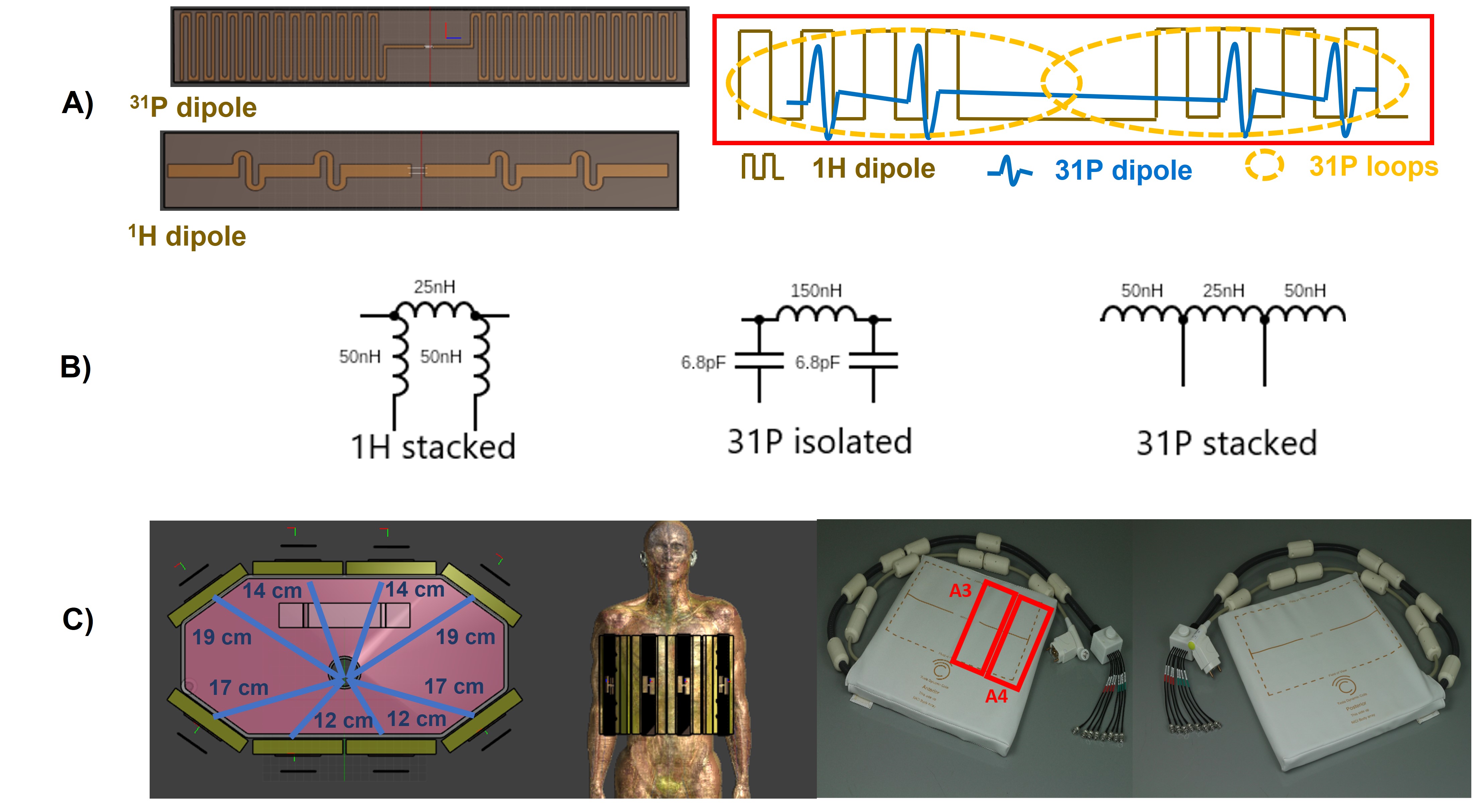
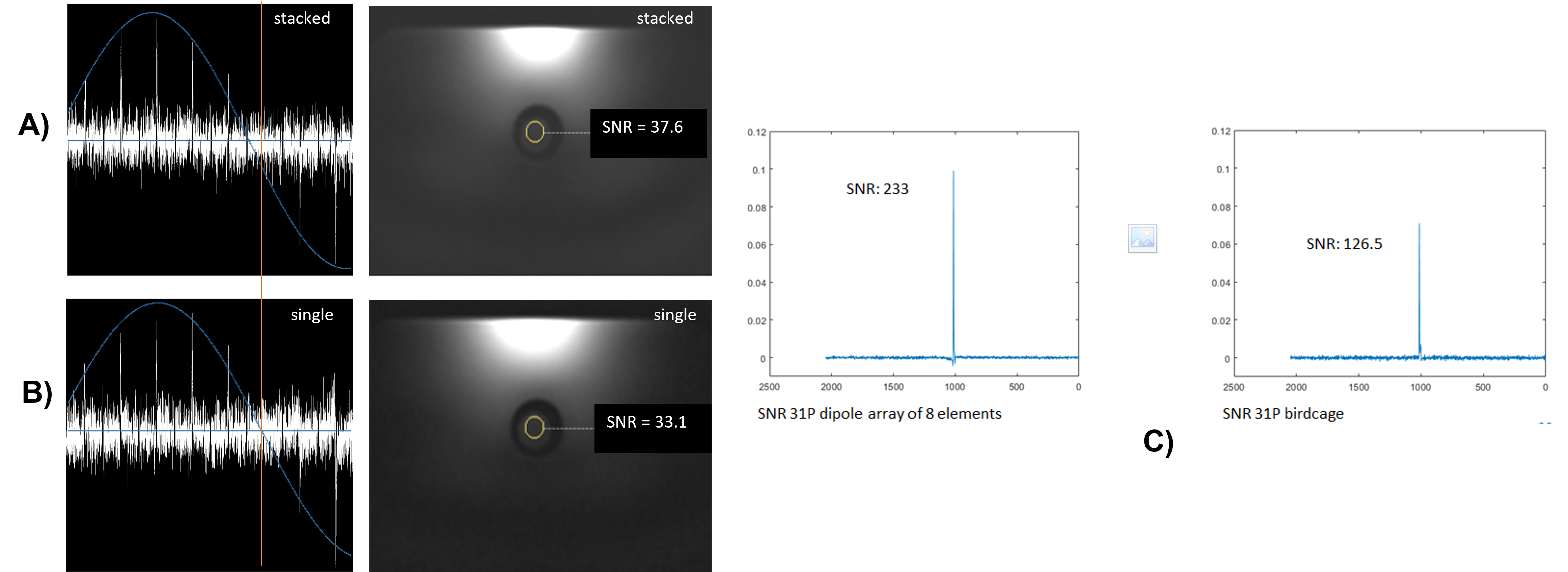
Figure 2: 31P pulse acquire flip angle series (A,B, left) and low flip angle 1H FFE scans (A,B, right), once with the antennas stacked (A) and as single antenna (B), all with identical RF power settings. Note that the optimum flip angle is reached with similar power settings, and that the signal intensity (reflecting B1+ times B1-) is almost the same. C) shows the 31P SNR improvement at liver depth by the use of a dipole array of 8 elements versus a birdcage, both with calibrated 90 degree excitation. The 8 31P dipoles were phased by means of adjusted cable lengths to obtain CP mode
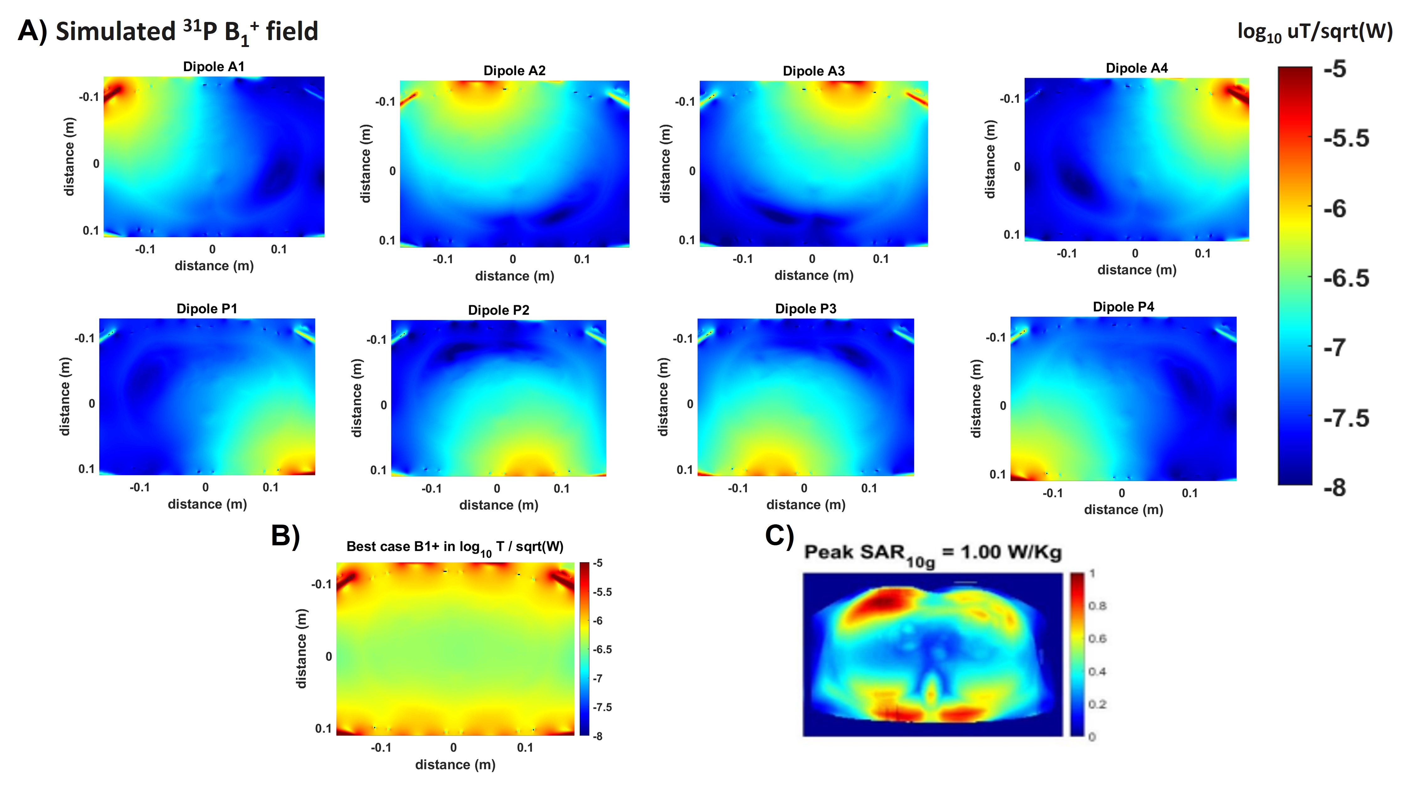

Figure 4: Table comparison between 31P B1 simulation values and experimental ones with same distance from each dipole and expected to be at liver depth. Average loss was 38% which includes cabling, TR switch and coil losses.

Figure 5: Phosphorus spectrum acquired in the liver with the new coil from Tesla DC in a healthy volunteer with only one dipole transmitting at once. This is the first spectrum we acquire with this new coil.