1444
Folded-End Dipole Transceiver Array for Human Whole Brain Imaging at 7 T.
Nikolai I. Avdievich1, Georgiy Solomakha2, Loreen Ruhm1, Anton V Nikulin1,3, Arthur Magill4, and Klaus Scheffler1,3
1High-Field MR Center, Max Planck Institute for Biological Cybernetics, Tübingen, Germany, 2Physics and Engineering, ITMO University, St. Petersburg, Russian Federation, 3Biomedical Magnetic Resonance, University of Tübingen, Tübingen, Germany, 4Medical Physics in Radiology, German Cancer Research Center, Heidelberg, Germany
1High-Field MR Center, Max Planck Institute for Biological Cybernetics, Tübingen, Germany, 2Physics and Engineering, ITMO University, St. Petersburg, Russian Federation, 3Biomedical Magnetic Resonance, University of Tübingen, Tübingen, Germany, 4Medical Physics in Radiology, German Cancer Research Center, Heidelberg, Germany
Synopsis
In spite of great benefits of 7T MRI, its further clinical development is associated with difficulties in designing RF coils. Recently, we developed a novel type of dipole antennas, a folded-end dipole. In this work we evaluated an 8-element transceiver folded-end dipole array for 7T human head imaging. The array provided ~20% higher Tx-efficiency and significantly better whole-brain coverage than that of a widely-used commercial array. In addition, we evaluated passive dipoles for decoupling the proposed array. In contrast to the common unfolded dipole array, the passive dipoles produce practically no destructive interference with the RF field of the array.
Purpose
To develop a robust design for a transmit dipole array coil for human whole brain imaging at 7T.Introduction
In spite of great benefits offered by ultra-high field (UHF,>7T) MRI, its further development toward clinical applications is associated with significant difficulties in the design of RF coils. Recently, dipole antennas (1) have been proposed and used to construct UHF head arrays (2-4). The dipole provides a unique simplicity while offering comparable Tx-efficiency (<B1+>/√P) and SNR to conventional loop designs. Recently, we developed a novel type of dipole elements, a folded-end dipole (4). In this work we developed and evaluated an 8-element transceiver (TxRx) bent folded-end dipole array for human head imaging at 7T (5). In addition, we evaluated passive dipole antennas (2,6,7) for decoupling the proposed array.Methods
The 8-element folded-end dipole array measured 200mm x 230mm (width x height) and 250mm in length. The array had no RF shield. During numerical optimization, we considered several alterations to the previously reported design (Fig.1A). First, we extended the dipoles above the head, which enhances the RF field in the superior head area (8). We tested three positions, i.e. the array aligned with head and moved by 20mm and 40mm out. To further improve the B1+ field at the superior head area (4,7,9), we added a local RF shield (Fig.1A). We also evaluated the Tx-performance of three other types of dipole arrays, i.e. the bent (unfolded) array, straight folded-end array, and straight (unfolded) array. All arrays were extended by 40mm above the head and included the local shield. In the next step, we added passive decoupling dipoles to the best array design. Figs.2A-C show placement of passive dipoles relative to active TxRx-dipoles. We simulated two types of passive dipoles, i.e. dipoles aligned with the active dipoles (decoupling 1), and passive dipoles moved away from the phantom to the level of the folded portion (decoupling 2). Decoupling 2 was suggested previously (10) to minimize destructive interference. For comparison, we tested both decoupling methods for the bent (unfolded) dipole array (Fig.2C). Figs.3A,B show the final geometry of the array design. Since the passive dipole near the nose caused very strong local SAR, it was removed, and all decoupled array designs (Fig.2) included only 7 passive dipoles. Electromagnetic (EM) simulations were performed using CST Studio Suite 2020 (Dassault Systèmes, Vélizy-Villacoublay, France) and the time-domain solver based on the finite-integration technique. All arrays were driven in the quadrature circular polarized (CP) mode (45° phase increment). All data were acquired on a Siemens Magnetom 7T human imaging system. We compared the new array to the commercial array coil (Nova Medical, Wilmington, MA, USA).Results and Discussion
Fig.1B shows results of numerical optimization of the folded-end dipole array. Extension the dipoles above the head and addition of the local shield increases the Tx-efficiency and SAR-efficiency (<B1+>/√pSAR, where pSAR is the peak local 10g SAR) by 55% and 46%, respectively. Bent arrays (both folded and unfolded) had similar Tx-efficiency ~10% higher than that of straight arrays. All arrays had similar SAR-efficiency. An additional benefit of the folded-end design is a reduction in the frequency change due to variation in head size (11). The folded-end dipole array demonstrated significantly less change in element resonance frequencies when both arrays were first tuned on the Duke voxel model and then loaded by the smaller Ella voxel model without readjustment (Fig.4). This effect is explained by the lower voltage along the conductor positioned near the head in the case of the folded-end dipoles. Figs.2D,E show ratios of transversal B1+ maps obtained using decoupled bent folded-end and unfolded arrays to those obtained using the same arrays without decoupling. Destructive interference produces peripheral voids and significantly reduces the central B1+ value (Fig.2E). In the case of the unfolded dipole array, <B1+>/√P is reduced by 9% and 27.5% for decoupling 1 and 2, respectively. For folded-end array and decoupling 2, however, this effect is substantially reduced and barely noticeable (Fig.2D). Fig.3D shows S-matrices measured using the bent folded-end dipole array with and without decoupling. The average coupling between neighboring channels measured -18.3dB and -12.1dB for the decoupled and coupled array versions, respectively. Finally, Fig.5 shows in-vivo data obtained using the new folded-end dipole array and commercial array coil. Averaged over a 130-mm transverse slab, B1+ measured 9.70 and 7.96 μT/√kW for the constructed dipole array and the commercial array, respectively. The dipole array provides significantly better coverage especially in the brain stem area.Conclusion
We developed, constructed, and evaluated the 8-element TxRx bent folded-end dipole array for human head imaging at 7T. The array demonstrated more than 20% higher Tx-efficiency and significantly better whole-brain coverage than that provided by a widely-used commercial array. We demonstrated that in contrast to the common unfolded dipole array, the passive dipoles moved away from the sample produce practically no destructive interference with the array RF field.Acknowledgements
Funding by the European Union (ERC Starting Grant, SYNAPLAST MR, Grant Number: 679927; ERC Advanced Grant SpreadMRI, Number: 834940) is gratefully acknowledged. SG acknowledges a support by Russian Science Foundation (Project 21-19-00707).References
1) Raaijmakers AJE, Ipek O, Klomp DWJ et al. Magn Reson Med 2011;66:1488-1497. 2) Clément J, Gruetter R, and Ipek Ö. Magn Reson Med 2019;81:1447–1458. 3) Connell IRO, Mennon RS IEEE Trans Med Imag 2019;38: 2177-2187. 4) Avdievich NI, Solomakha G, Ruhm L, Bause J, Scheffler K, Henning A. Magn Reson Med 2020; 84:3453–3467. 5) Avdievich NI, Solomakha G, Ruhm L, Magill AW, Scheffler K. NMR in BioMed 2021;34(8):1-14. 6) Yan X, Zhang X, Wei L, Xue R. Appl Magn Res 2015;46:59-66. 7) Avdievich NI, Solomakha G, Ruhm L, Henning A., Scheffler K. Magn Reson Med 2021;86:581–597. 8) Avdievich NI, Hoffmann J, Shajan G, Pfrommer A, Giapitzakis IA, Scheffler K, Henning A, NMR in Biomed 2017, 30(2);1-12. 9) Alecci M, Collins CM, James Wilson J, Liu W, Smith MB, Jezzard P. Magn Reson Med 2003;49:363-370. 10) Neumann GF, Ladd ME, and Magill AW. In Proceedings of the 20th Annual Virtual Meeting ISMRM, 2020, p.4023. 11) Avdievich NI, Solomakha G, Ruhm L, Scheffler K, Henning A, Magn Reson Med 2019;82:811–824.Figures
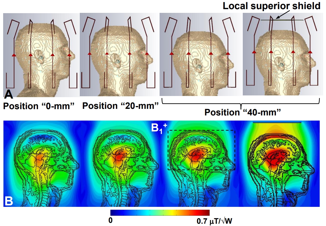
Figure 1. EM
simulation models (A) and corresponding B1+
maps (B) obtained using various versions of the bent folded-end array all
loaded by the Duke voxel model. Position “0-mm” corresponds to the edge of the
array aligned with head. Positions “20-mm”and “40-mm” correspond to the array
moved by 20 and 40 mm in the superior direction, respectively. Last two models
also include a local superior shield. 130-mm averaging transverse slab is shown
in Figure 1B by dashed line.
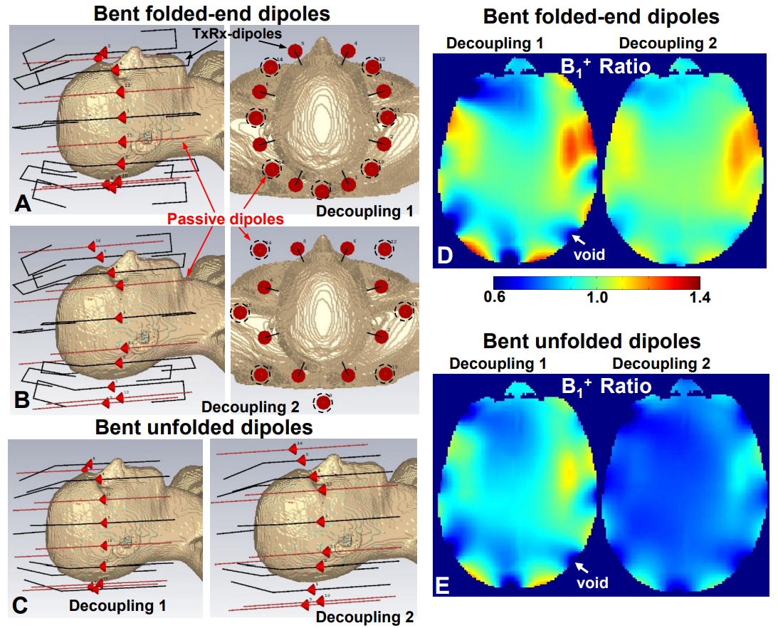
Figure 2. EM
simulation models of bent folded-end dipole arrays decoupled using: passive dipoles
aligned (A, decoupling 1) and moved away (B, decoupling 2) from active dipoles.
C) EM simulation models of bent (unfolded) dipole arrays decoupled using two
types of decoupling. All arrays are driven in the CP mode (45º phase increment)
and loaded by the Duke voxel model. Active and passive dipoles are shown in
black and red, respectively. Transverse maps of the B1+ ratios obtained using decoupled
folded-end (D) and unfolded (E) dipole arrays to that obtained by arrays
without decoupling.

Figure 3. A) EM
simulation model of the final bent folded-end dipole array design. B) Photo of
the array with the cover and RF shield removed. C) The inner surface of the
cover with the passive dipoles attached. Examples of an active dipole, passive
dipole and tuning inductor are shown in Figs.4A, B, and C. D) S-matrices measured using the coupled
and decoupled (method 2) bent folded-end dipole arrays loaded by a male head
(570 mm in circumference). Coupling
between neighboring elements is marked by a dashed line. E) Numeration of the
elements.
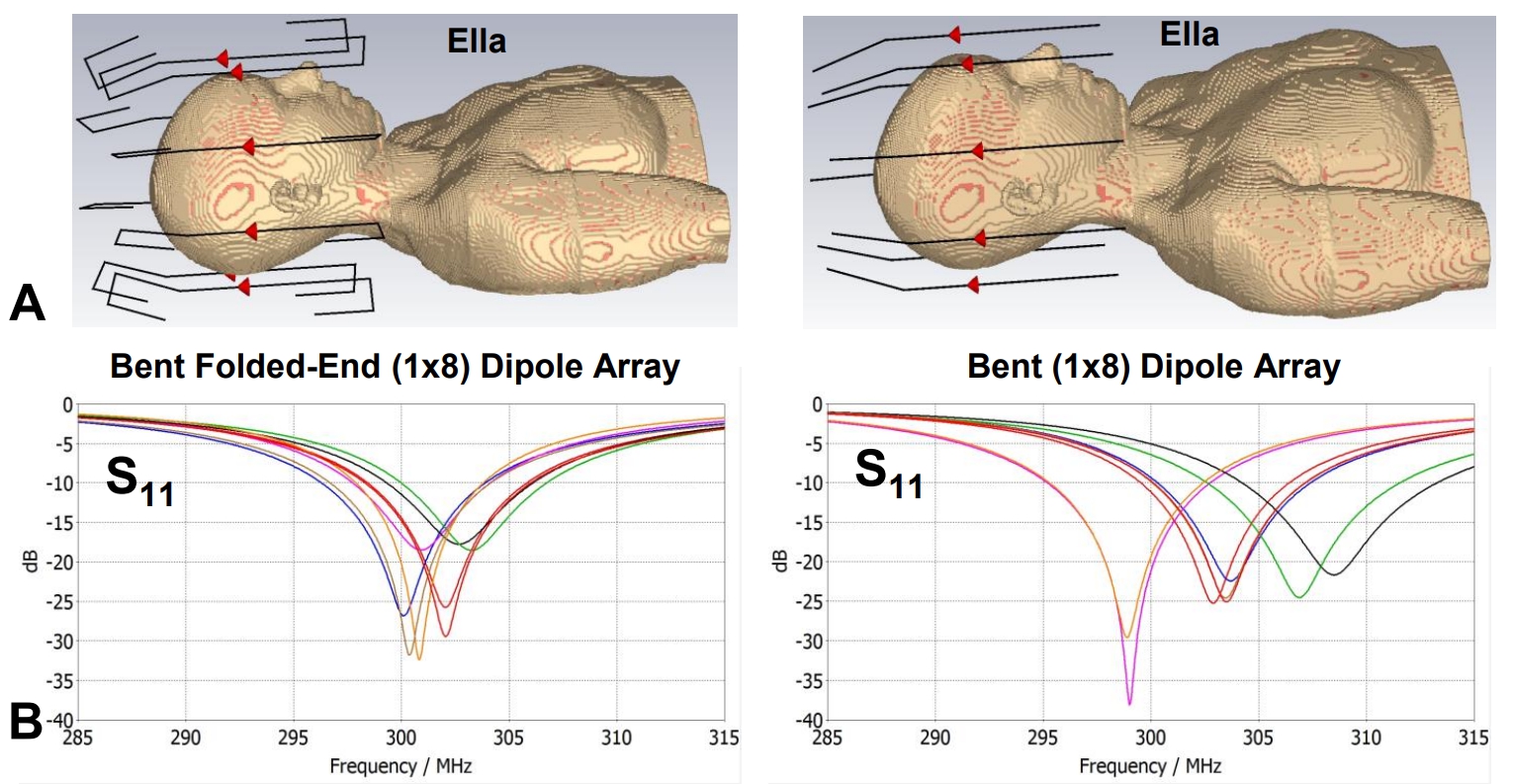
Figure 4. A) EM
simulated models of bent folded-end and unfolded dipole arrays loaded by the
Ella voxel model. B) Snn frequency dependencies
obtained for all eight elements of bent folded-end and unfolded dipole arrays
loaded by the Ella voxel model. In both cases, arrays were initially tuned on
the larger Duke voxel model. Then the Duke model was replaced by Ella without
any further adjustment.
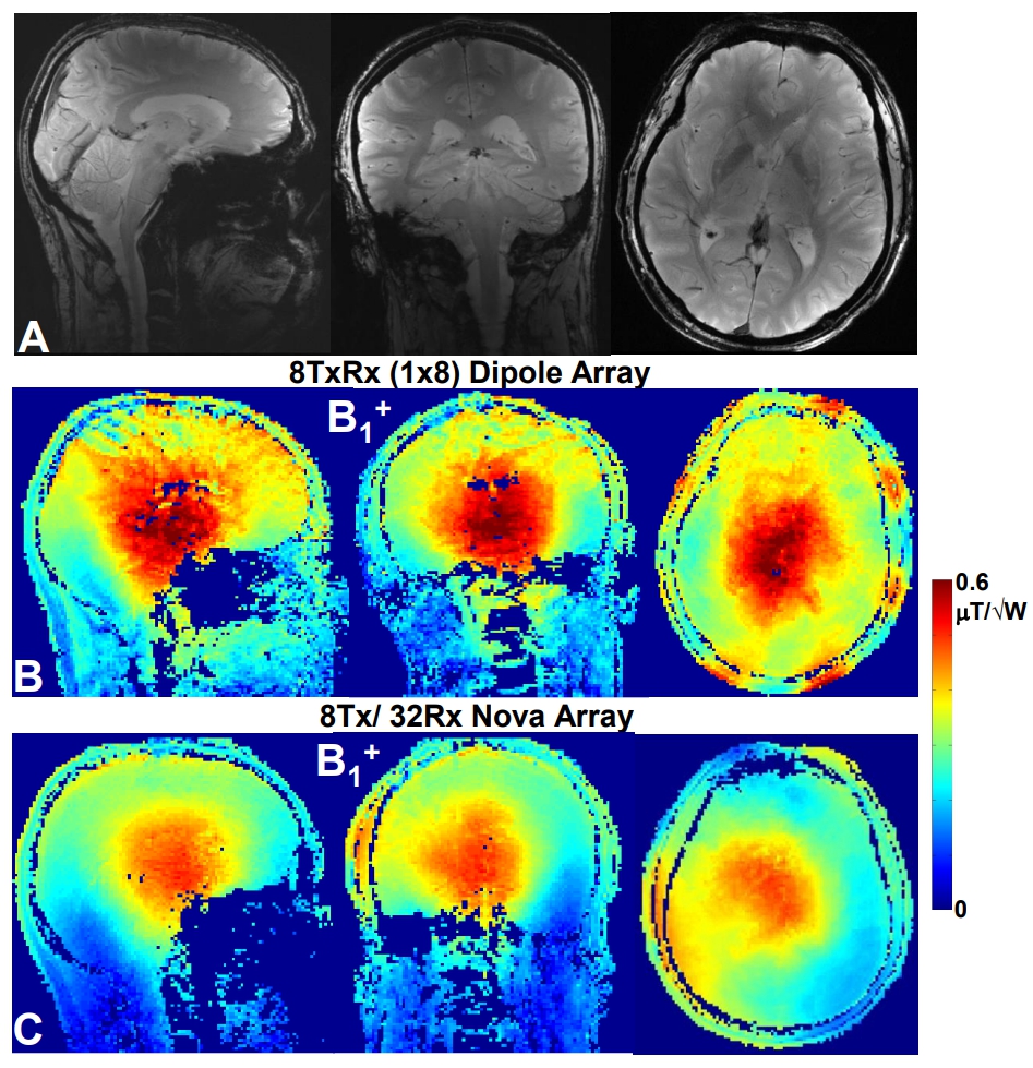
Figure 5. In-vivo
human brain GRE images (A) and corresponding B1+ maps (B) obtained for the same male
subject as in Fig.4 using bent folded-end dipole array. C) In-vivo human brain B1+ maps obtained
using the commercial array for the same male subject as above.
DOI: https://doi.org/10.58530/2022/1444