1376
Improving image quality and acoustic transparency in MRgFUS at 3T using a low-profile, flexible receive coil array1Department of Radiology, Weill Cornell Medicine, New York, NY, United States, 2GE Healthcare, Aurora, OH, United States, 3Department of Neurological Surgery, Weill Cornell Medicine, New York, NY, United States
Synopsis
Transcranial MRgFUS has been successfully used to treat a variety of neurodegenerative diseases. However, body coil brain image quality is poor, and a low-signal band artifact may occur in some regions due to RF wave reflections. Further, acoustic coil transparency has not been addressed extensively to date. In this work, we simulate a 10-channel coil design that can significantly increase the SNR by a factor of 20 over the body coil and thus indirectly improve the signal at the region of interests. Acoustic simulations/experiments exhibit transparency of the FUS-Flex coil as high as 97% at 650 kHz.
Introduction
Non-invasive transcranial magnetic resonance-guided focused ultrasound (MRgFUS) can be used to treat a variety of neurodegenerative diseases1,2. However, the use of the vendor's integrated body coil at 3T, together with the large conductive transducer, results in poor brain image quality and a low-signal band artifact that can occur, for example, at the thalamus region, which is the region of interest (ROI) for essential tremor. A number of solutions have been presented in the literature to solve this problem directly by shifting the low-signal band3-5, or indirectly by using radiofrequency (RF) surface receive coils to achieve a better signal-to-noise ratio (SNR)6-8 in the low-signal band. However, the evaluation of the acoustic footprint of dedicated MRgFUS coils has not been addressed in great detail7. In previous work, we proposed an 8-channel coil (FUS-Flex)9,10. This configuration does not directly reduce the low-signal band artifact, but experiments show an increase of the SNR in the thalamus region by a factor of ~10 (~7.6 with 2-fold acceleration) using the proposed coil compared to the body coil. In this work, we expand this concept by adding phased RF coils placed between the patient’s head and the transducer. We hypothesize that the SNR in the low-signal artifact can be increased. Moreover, we expand on the acoustic transparency of our design by tailoring the acoustic footprint to incur minimal signal deviation.Methods
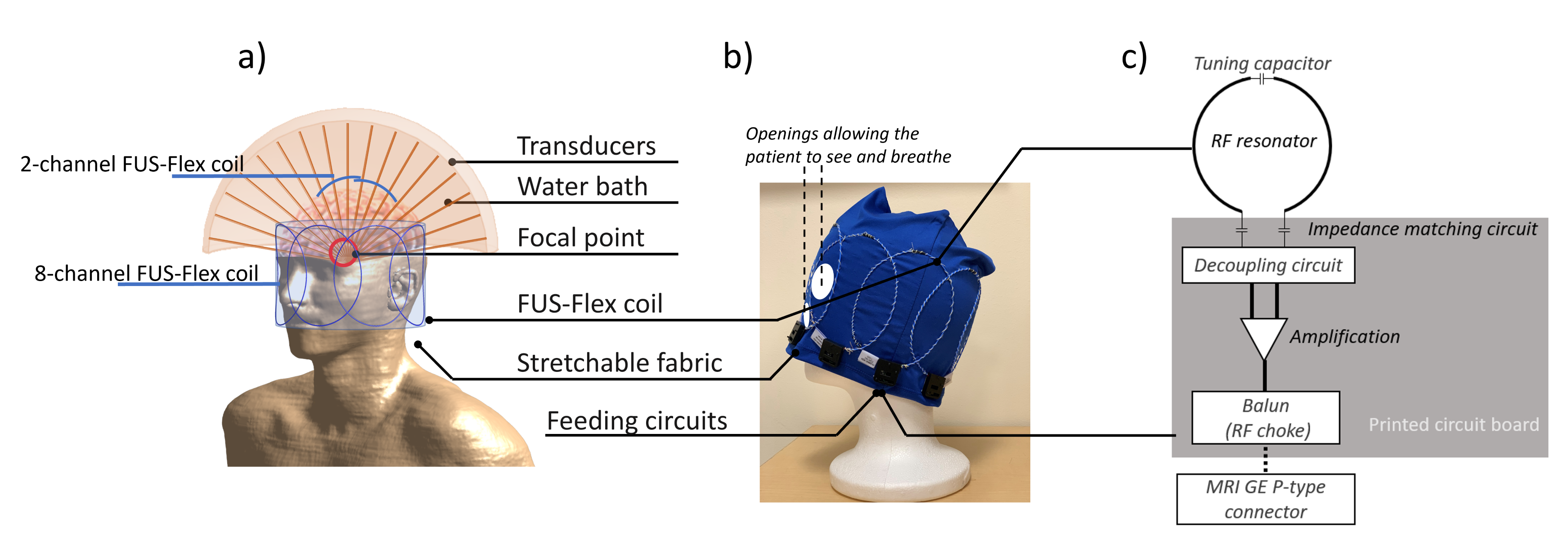
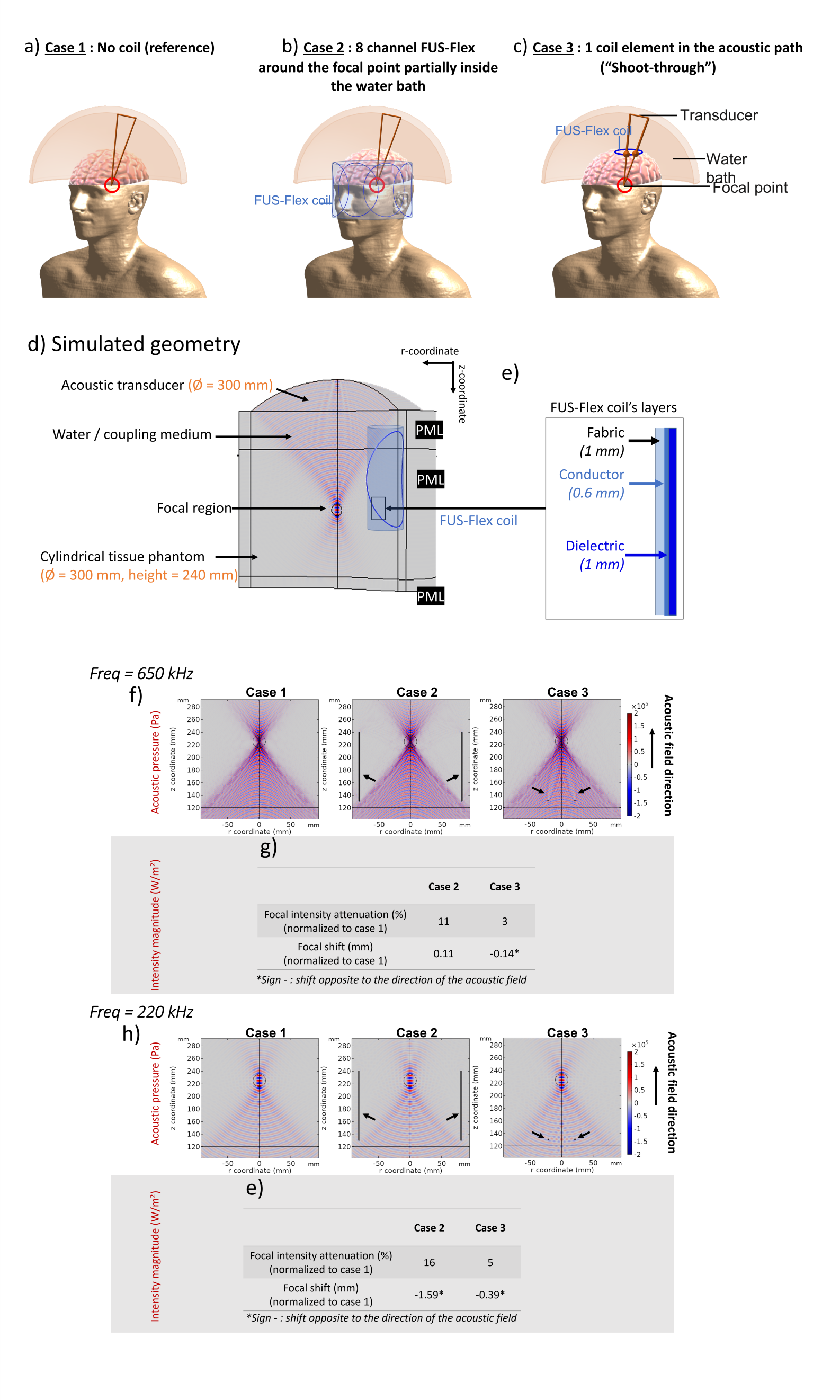
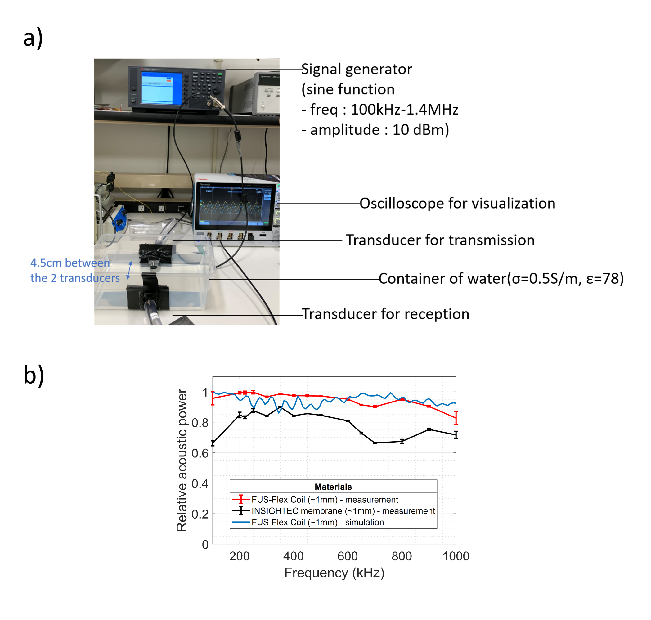
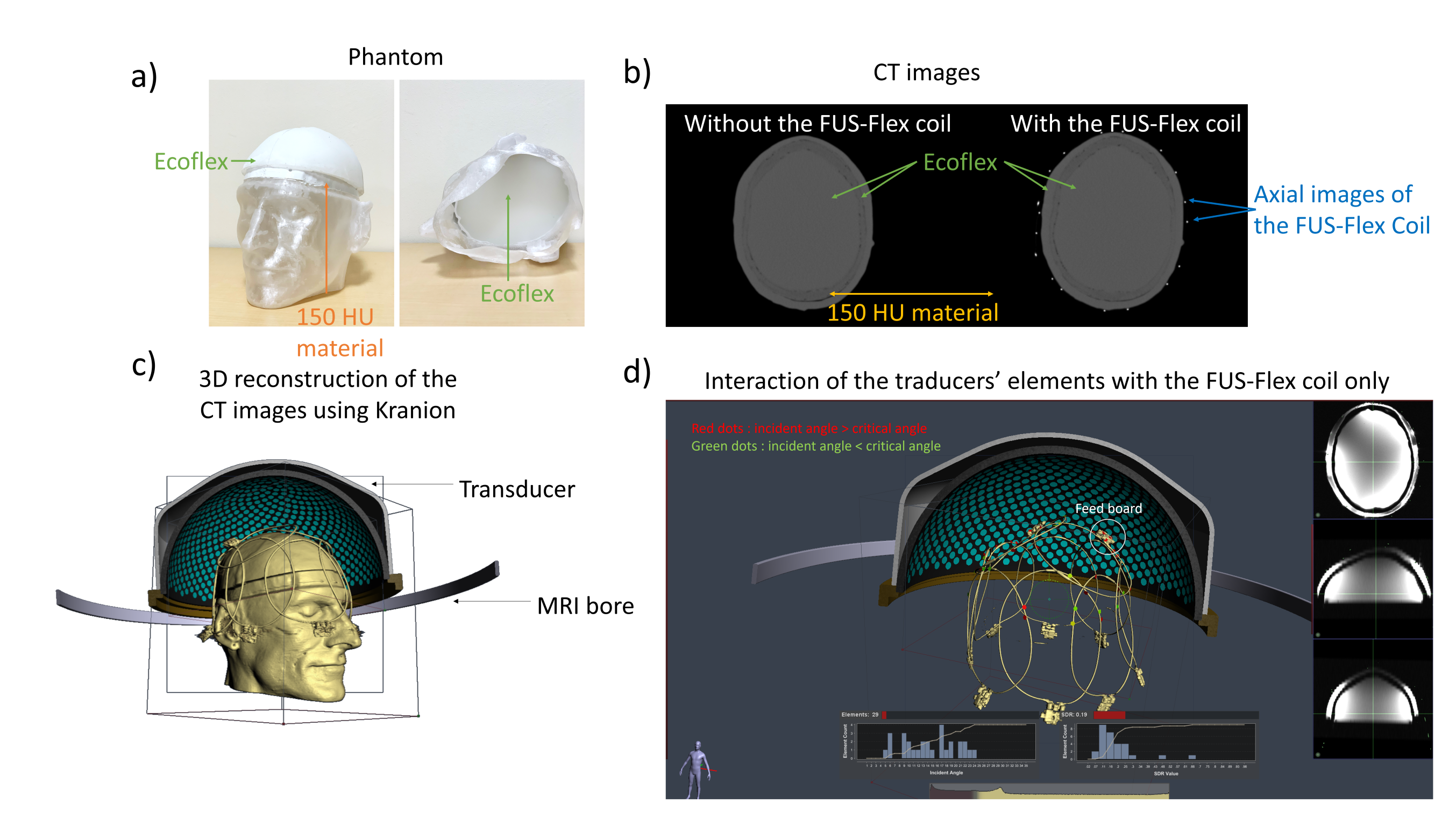
The FUS-Flex coil concept is inspired by highly flexible and thin coil technology11,12. Our previous 8-channel FUS-Flex design9,10 was updated by adding 2 phased RF coils placed between the patient’s head and the transducer at a distance of 1cm above the head (Figure 1), bringing the total number of RF elements to 10.Acoustic footprint: First, the numerical evaluation of FUS-Flex acoustic transparency in our previous work9,10 was expanded to study a 30cm-diameter transducer and multiple scenarios using COMSOL Multiphysics® (Figure 2a). Second, the acoustic attenuation of 1 FUS-Flex element was evaluated experimentally on the bench using 2 immersion transducers (500kHz, Sensor Networks) in a container of water (Figure 3a). The acoustic transmission attenuation was measured and was compared to a reference “acoustically-transparent” INSIGHTEC sealant membrane8. Third, we used computed tomography (CT) to correct for unwanted focal point displacement caused by the coil, inspired from aberration correction of the patient's skull bone prior to MRgFUS exams. We scanned the FUS-Flex coil using MRI and CT (Hounsfield unit>3000) on a head phantom (Figure 4a) and evaluated the number of transducer elements interacting with the coil using the open-source tool Kranion13.
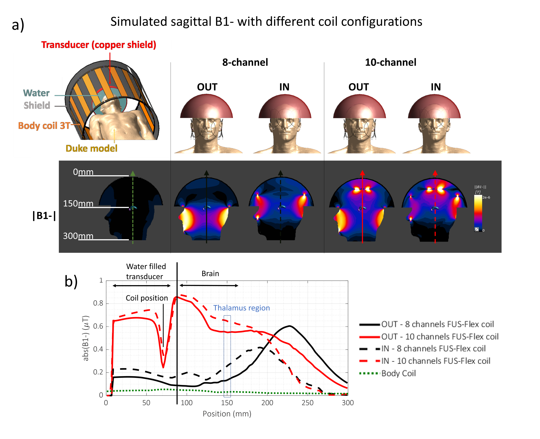
Electromagnetic simulations: We replicated the low-signal bands that stem from the influence of the transducer on the transmit field using a semispherical water-filled copper-coated geometry, placed over the head of a virtual body model, Duke (IT’IS Foundation) and compared our previous 8- and the proposed 10-channel designs (Figure 5). The simulations were performed with the coil fully outside or partially inside the water-filled transducer. The fully outside configuration could prove useful to acoustic transparency if the SNR is not negatively affected.
Results
Acoustic footprint: The clinically relevant case 2 (Figure 2) resulted in a 0.11mm and 1.59mm displacement of the focal point at 650kHz and 220kHz, respectively. In case 3, minor signal fluctuations were observed (<5%) with a shift of the focal point by less than 0.39mm for both frequencies. The experimental measurements showed a relative shoot-through acoustic attenuation (normalized to the case without a coil) varies from about 1% to 5% in the frequency range from 100kHz to 700kHz (Figure 3b), comparable to case 3 results in simulation. The FUS-Flex coil outperforms the INSIGHTEC sealing membrane, which is specifically made to be acoustically transparent by the vendor. Only ~3% of the transducer elements interacted with the coil, even with a 2-coil feed board placed above the phantom (Figure 4).Electromagnetic simulations: Despite its receive-only nature, the coil increases SNR in the low-signal band and allows for top-of-head coverage, resulting in an SNR increase at the thalamus region by a factor of 5 and 20 over the original configuration (8-channel outside the water bath)9,10 and the body coil, respectively. Placing the coil outside the water bath had minimal negative impact on the SNR (~10% reduction in the thalamus region) while minimizing acoustic interference.
Discussion and conclusions
The acoustic footprint of the FUS-Flex concept is negligible compared to the attenuation/aberration caused by the skull14, and only 3% of the transducers interact with the design when partially placed inside the transducer. As a result, we do not expect a major need to refocus the acoustic target location beyond what is already employed when correcting for the skull. The electromagnetic simulations show an SNR increase of 20× over the body coil in the thalamus as well as increased top-of-head coverage when using 2 additional channels. While receive-only in nature, this design improves signal in the low-band artifact. Future work will involve testing the coil in vivo during an MRgFUS procedure.Acknowledgements
This work was supported by NIH
R00EB024341 and GE Healthcare.
References
1. Chazen JL, Travis S, Kaplitt MG. Cranial MR-guided Focused Ultrasound for Essential Tremor. Clinical Neuroradiology. 2019;29(2):351-357.
2. Beisteiner R, Matt E, Fan C, et al. Transcranial Pulse Stimulation with Ultrasound in Alzheimer's Disease—A New Navigated Focal Brain Therapy. Advanced Science. 2020;7(3):1902583.
3. Yan X, Allen S, Grissom WA. “Propeller Beanie” Passive Antennas to Alleviate Dark Bands in Transcranial MR-Guided Focused Ultrasound. Paper presented at: In Proceedings of the 28th Annual Meeting of ISMRM 2020.
4. Yan X, Allen S, Meyer CH, Grissom WA. Improvements in in vivo imaging and temperature mapping using passive “propeller-beanie”antenna in transcranial MR-guided focused ultrasound. Paper presented at: In Proceedings of the 29th Annual Meeting of ISMRM2021.
5. Hadley JR, Odéen H, Merrill R, et al. Improving image quality in transcranial magnetic resonance guided focused ultrasound using a conductive screen. Magnetic Resonance Imaging. 2021;83:41-49.
6. Watkins RD, Bitton R, Butts Pauly K. Integration of an Inductive Driven Axially Split Quadrature Volume Coil with MRgFUS System for treatment of Human Brain. In Proceedings of the 22th Annual Meeting of ISMRM; 2014; Milan, Italy.
7. Corea J, Ye P, Seo D, Butts-Pauly K, Arias AC, Lustig M. Printed Receive Coils with High Acoustic Transparency for Magnetic Resonance Guided Focused Ultrasound. Scientific Reports. 2018;8(1):1-10.
8. Bitton RR, Sheingaouz E, Assif B, et al. Evaluation of an MRI receive head coil for use in transcranial MR guided focused ultrasound for functional neurosurgery. International Journal of Hyperthermia. 2021;38(1):22-29.
9. Saniour I, Robb F, Taaracila V, et al. Acoustically transparent and low profile head coil for high precision magnetic resonance guided focused ultrasound at 3T. Paper presented at: In Proceedings of the 29th Annual Meeting of ISMRM2021.
10. Saniour I, Robb F, Taracila V, et al. Attenuation of the dark band artifact in MR-guided focused ultrasound using an ultra-flexible high-sensitivity head coil. Paper presented at: In Proceedings of the 29th Annual Meeting of ISMRM 2021.
11. McGee KP, Stormont RS, Lindsay SA, et al. Characterization and evaluation of a flexible MRI receive coil array for radiation therapy MR treatment planning using highly decoupled RF circuits. Physics in Medicine & Biology. 2018;63(8):08NT02.
12. Collick BD, Behzadnezhad B, Hurley SA, et al. Rapid development of application-specific flexible MRI receive coils. Physics in Medicine & Biology. 2020;65(19):19NT01.
13. Sammartino F, Beam DW, Snell J, Krishna V. Kranion, an open-source environment for planning transcranial focused ultrasound surgery: technical note. Journal of Neurosurgery. 2020;132(4):1249-1255.
14. Pinton G, Aubry J-F, Bossy E, Muller M, Pernot M, Tanter M. Attenuation, scattering, and absorption of ultrasound in the skull bone. Medical Physics. 2011;39(1):299-307.
Figures