1373
Hybrid Superconducting-Permanent Magnet Designs for Short Mid-Field MRI Magnets1MGH, Charlestown, MA, United States, 2MIT, Cambridge, MA, United States
Synopsis
Mid-field (0.5T) MRI is an attractive alternative to higher field strengths for improved cost, accessibility and patient comfort. Magnet length is a major determinant of patient comfort/acceptance but is constrained by escalating wire costs. We present a mid-field magnet design using rare-earth permanent magnets to supplement solenoidal superconducting windings, enabling shorter bore lengths than superconducting windings alone. The optimization problem is formulated and solved using linear programming. For a given superconducting wire length, we demonstrate that adding rare-earth materials can reduce bore lengths by 10% using <250kg of rare-earth material for a 5ppm, 0.5T B0 specification over a 450mm DSV.
Introduction
MRI scanners based on mid-field (0.5T) superconducting solenoid magnets have emerged as an attractive compact scanning option with the potential to increase accessibility where system and operating costs or citing footprint present a barrier [1-5]. Furthermore, their low field strength offers the potential for increasing the range of implants that can be scanned due to either safety or susceptibility artifact improvements [1, 3, 6]. Finally, the >3x lower field strength can improve patient comfort and acceptance by allowing shorter bore or larger diameter magnets [1, 7].The trade-off between magnet length and superconducting wire length (a proxy for cost) has been previously examined in optimal solenoid designs for a given bore diameter, imaging DSV and homogeneity target [8]. In this study, we attempt to further reduce the bore length of a 0.5T B0 superconducting solenoid magnet design by employing rare-earth permanent magnets inside the bore to supplement and shape the field from the superconducting windings. This becomes possible in mid-field MRI since high remanence and coercivity materials allow for significant field contributions relative to the superconducting windings while retaining their original magnetization strength and direction. We jointly optimize the placement of rare-earth permanent magnet materials as well as the superconducting windings. We examine the effect of two types of “ring” structures (Fig. 1) placed inside the superconducting solenoid; an Aubert ring pair (with radially directed magnetization) [9] and a ring pair with axial magnetization (either parallel or antiparallel to B0). We compare the hybrid supercon/permanent magnet design to a traditional “supercon-only” optimized design.
Methods
The geometry of the system is shown in Fig. 2. The symmetric magnet uses equi-radius windings and permanent magnet rings in the warm-bore. Compared designs have a 5ppm target homogeneity in a 450mm imaging DSV and identical patient tube and gradient coil spaces. In addition to simply comparing the design with no permanent magnet material, we also compare to a design with reduced supercon winding diameter (capturing the space used by the permanent magnets). Magnetic field computations for current loop sources and permanent magnet sources used Magpylib [10]. Optimization follows the linear programming methodology described by Xu et al. [8, 11] which optimized the strength and location of the supercon ring currents and studied the cost-length tradeoff of the family of optimized designs using L-curves. Here we add the strength and location of the permanent magnet rings to supercon ring currents as a joint optimization. This formulation allows for rapid computations, and guarantees globally optimal solutions given solution existence, while promoting sparsity of the rings to inherently aid in “buildability” of the magnet [11]. Fig. 2d details the objective function and DSV target field constraints used in the joint optimization problem. The l1-norm of currents and remanences can be cast into LP form by introduction of auxiliary variables, casting absolute values into two linear inequalities.Fig. 2d also shows the candidate source locations and defines the magnet length neglecting formers and cryostat at the magnet ends. The field is computed over 41 points along a quarter circle arc of a central slice of the DSV, utilizing symmetry and properties of solutions to Laplace’s equation in source-free regions. Fig 2e presents additional optimization parameters used for source material placement. CVXPY is used to compute optimized solutions over currents and remanences [12, 13] by superimposing the fields from candidate source locations.
Results
Fig. 3 shows example homogeneity contours for a 1000mm bore length, 0.5T design at 5ppm homogeneity using 250kg of rare earth material for the geometry in Fig 2b. Note that the superconducting-only design is highly inhomogeneous at the wire length (wire-cost) chosen but summed with the pattern contributed by 250 kg Aubert rings yields the desired 5ppm homogeneity. Fig. 4 shows the L-curve tradeoffs between current requirements (i.e. wire-length/cost) and magnet length for designs employing permanent magnet rings of differing total rare-earth material mass as well as the conventional supercon-only design, all with a 5ppm homogeneity and 0.5T B0 specification. Superconducting wire length can be traded for rare-earth material and a shorter over-all magnet can be achieved by adding rare-earth material. Allowing use of permanent magnet rings of material polarized along the bore offers only minor benefits over the Aubert rings alone. For the given wire-length constraint marked by the horizontal dashed line in Fig. 4b, adding up to 250 kg of permanent magnet material into the bore allowed roughly a 10% decrease in bore length.Discussion/Conclusion
In this work, we compare a conventional 0.5T optimized superconducting magnet design to a novel design adding rare-earth material inside the superconducting bore. We show that the addition of rare-earth material decreases the burden on superconducting windings allowing overall shorter magnet designs in mid-field MRI scanners. Given that supercon wire length tends to skyrocket for magnet lengths below a critical “knee” in the L-curve [8], adding permanent magnet material inside the bore, although itself adding cost, might be an effective way to shorten the magnet length. Future work will examine the use of the full ability to choose the direction of the permanent magnet magnetization, rather than restricting magnetizations purely in the radial or axial directions.Acknowledgements
No acknowledgement found.References
[1] Marques, J. P., Simonis, F. F. J., & Webb, A. G. (2019). Low-field MRI: An MR physics perspective. In Journal of Magnetic Resonance Imaging (Vol. 49, Issue 6, pp. 1528–1542). John Wiley and Sons Inc. https://doi.org/10.1002/jmri.26637
[2] Wald, L.L., McDaniel, P.C., Witzel, T., Stockmann, J.P. and Cooley, C.Z. (2020), Low-cost and portable MRI. In Journal of Magnetic Resonance Imaging, (Vol. 52: 686-696. https://doi.org/10.1002/jmri.26942
[3] Stainsby, J. A., Bindseil, G. A., Connell, I. R., Thevathasan, G., Curtis, A. T., Beatty, P. J., Harris, C. T., Wiens, C. N., & Panther, A. (2019). Imaging at 0.5 T with high-performance system components System Components. ISMRM 27th Annual Meeting and Exhibition. 1194
[4] Panther, A., Thevathasen, G., Connell, I. R. O., Yao, Y., Wiens, C. N., Curtis, A. T., Bindseil, G. A., Harris, C. T., Beatty, P. J., Stainsby, J. A., Cunningham, C. H., Chronik, B. A., & Piron, C. (2019). A Dedicated Head-Only MRI Scanner for Point-of-Care Imaging Barriers to MRI being used at the point-of-care. ISMRM 27th Annual Meeting and Exhibition. 3679
[5] Harris, C. T., Curtis, A. T., Wiens, C. N., Beatty, P. J., & Stainsby, J. A. (2020). Acoustic Behavior of High Performance Imaging on a Head-only 0.5T Scanner with Asymmetric Gradients. ISMRM & ASRT Virtual Conference and Exhibition. 4207
[6] Connel, I., Panther, A. (2019). Increasing MRI Safety for Patients with Implanted Medical Devices: Comparisons of a 0.5T Head-Only MRI to 1.5T and 3T. 57th Annual ASNR Meeting and Symposium Neuroradiologicum. 3569
[7] Chen, S., Hu, P., Gu, Y., Pang, L., Zhang, Z., Zhang, Y., Meng, X., Cao, T., Liu, X., Fan, Z., & Shi, H. (2019). Impact of patient comfort on diagnostic image quality during PET/MR exam: A quantitative survey study for clinical workflow management. Journal of Applied Clinical Medical Physics, 20(7), 184–192. https://doi.org/10.1002/acm2.12664
[8] Xu, H., Conolly, S. M., Scott, G. C., & Macovski, A. (1999). Fundamental Scaling Relations for Homogeneous Magnets. ISMRM
[9] Aubert, G., Centre National de la Recherche Scientifique CNRS, 1991. Cylindrical permanent magnet with longitudinal induced field. U.S. Patent 5,014,032.
[10] Ortner, M., & Coliado Bandeira, L. G. (2020). Magpylib: A free Python package for magnetic field computation. SoftwareX, 11. https://doi.org/10.1016/j.softx.2020.100466
[11] Xu, H., Conolly, S. M., Scott, G. C., & Macovski, A. (2000). Homogeneous Magnet Design Using Linear Programming. In IEEE TRANSACTIONS ON MAGNETICS (Vol. 36, Issue 2).
[12] Agrawal, A., Verschueren, R., Diamond, S., & Boyd, S. (2017). A Rewriting System for Convex Optimization Problems. http://arxiv.org/abs/1709.04494
[13] Diamond, S., & Boyd, S. (2016). CVXPY: A Python-Embedded Modeling Language for Convex Optimization. http://arxiv.org/abs/1603.00943
Figures
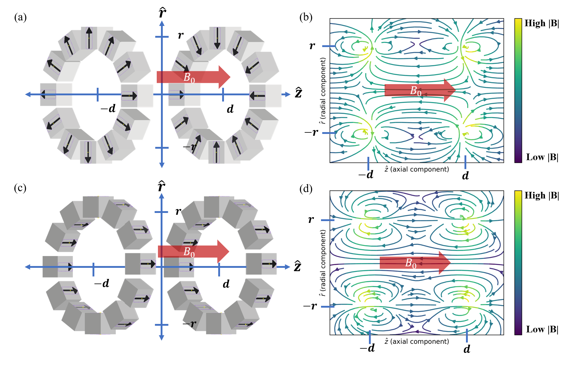
Figure 1 (a) Aubert ring configuration of rare earth permanent magnets. (b) Illustrated field profile of configuration in (a). (c) Rare earth magnets aligned parallel with B0 field (reminiscent of ferroshims). Note that unlike ferroshims, rare earth magnets can be oriented to flip magnetization, so that they are aligned anti-parallel with B0. (d) Illustration of the field lines from the magnet configuration in (c).
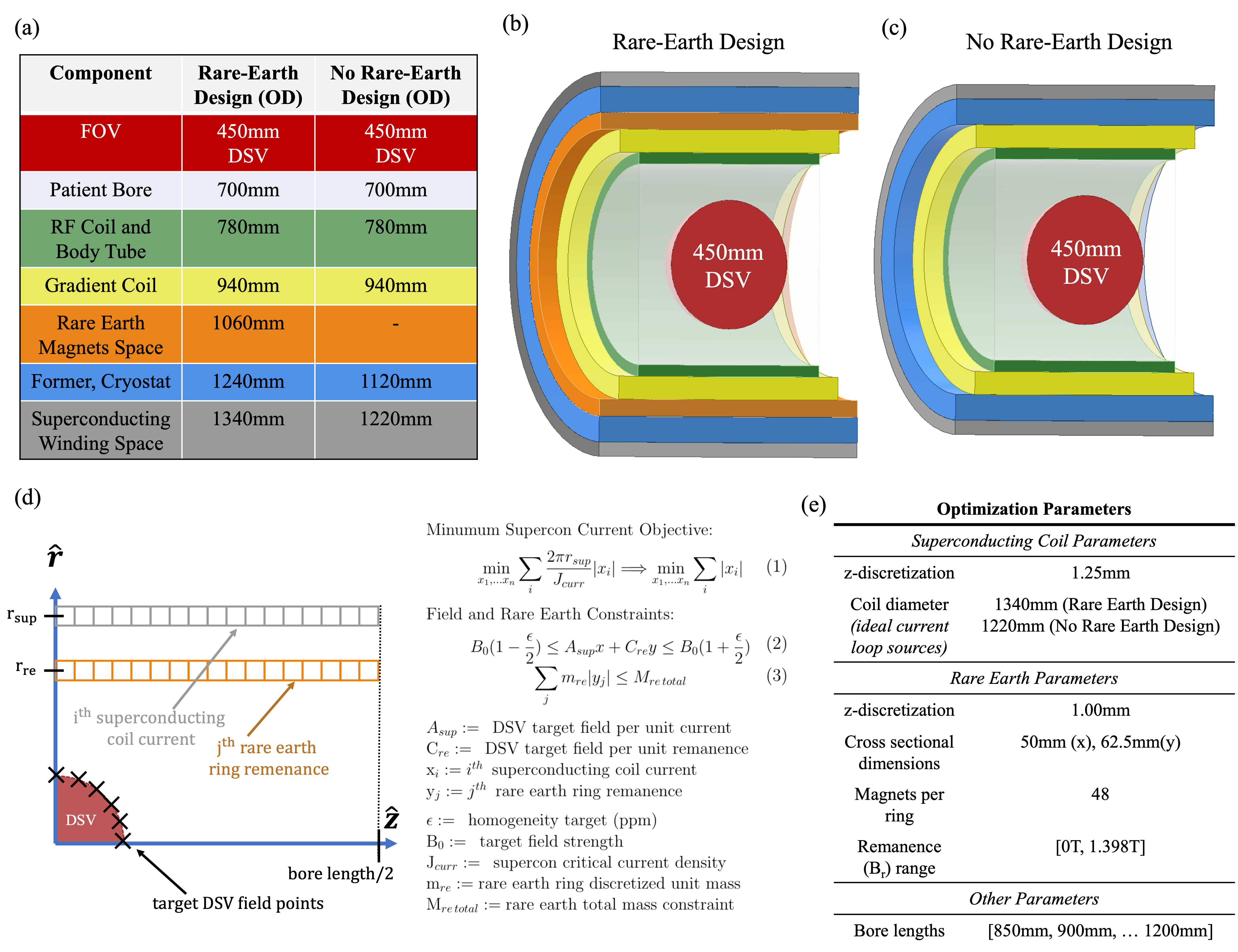
Figure 2 (a) Table of dimension parameters detailing the magnet designs (b), (c). (b) Rare-Earth magnet design with space for rare earth magnets (orange region) to supplement the superconducting windings (gray region) for short magnet design. (c) Design without rare-earth materials space for comparison. (d) Schematic of optimization for magnet design and optimization objective and constraints, closely following methodology from [8, 11]. (e) Relevant parameters used in optimization for magnet design.
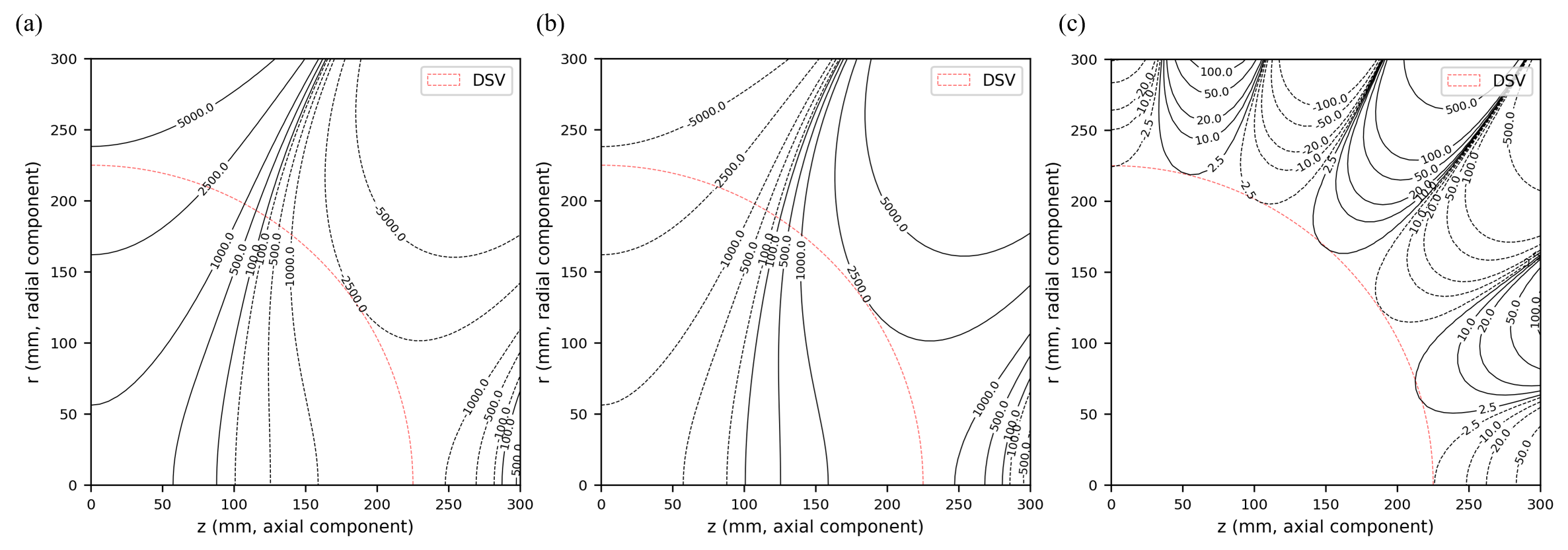
Figure 3 Homogeneity contours from joint design using superconducting windings and Aubert rings. This considers a 1000mm bore length, 0.5T design at 5ppm homogeneity, using 250kg of rare earth material. It requires approximately 2.94 * 106 ampere turns (a) Superconducting homogeneity lines (b) Aubert ring homogeneity lines (c) Total design homogeneity lines. Note that the rare-earth Aubert rings reduce the superconducting only homogeneity, reducing the total current required for the design.
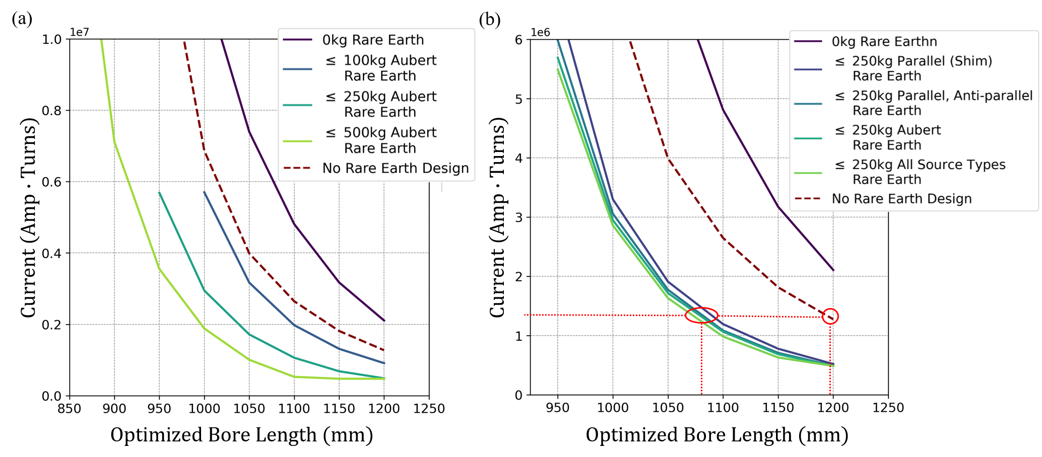
Figure 4 (a) L-curves illustrating the tradeoffs between constrained length max rare-earth mass for Aubert rings only in the rare-earth space (b) tradeoffs between constrained length, and rare-earth configurations. For all designs the field target is 0.5T at 5ppm. Note that for a given current, designs with rare-earth material enable shorter magnet designs (Circled in red: design at a 1.27*106 amp-turn current can be reduced by 12cm with inclusion of rare earth materials)