1369
Design Analysis and Prototype Construction of PNS Optimized MRI Gradient Coils1Martinos Center for Biomedical Imaging, Charlestown, MA, United States, 2Harvard Medical School, Boston, MA, United States, 3Computer Assisted Clinical Medicine, Medical Faculty Mannheim, Heidelberg University, Heidelberg, Germany, 4Harvard Graduate Program in Biophysics, Harvard University, Cambridge, MA, United States, 5Harvard-MIT Division of Health Sciences and Technology, Boston, MA, United States
Synopsis
We describe the process of designing and analyzing two body gradient coils with and without PNS optimization suitable for prototype construction and experimental validation. The optimized coil achieves a 51% increase in PNS thresholds at a 15% inductance penalty. Both coils are construction-ready (single continuous wire path) and have realistic and matched design characteristics (actively shielded, torque/force balanced, high field linearity in 40 cm ROL). We are in the process of constructing coil prototypes, with the ultimate goal of experimentally validating their PNS differences.
Target audience
MRI gradient designers, safety researchers and imaging scientistsPurpose
Peripheral Nerve Stimulation (PNS) limits the usable image encoding performance in state-of-the-art body and head gradient coils [1-3]. We recently developed an approach to model and incorporate PNS metrics in the numeric coil winding optimization to generate PNS optimized coils [4]. This optimization can increase PNS thresholds by up to 90% while satisfying traditional engineering constraints (linearity, FOV, shielding, torque/force balancing). In this work, we compare two body gradient coils (PNS constrained and unconstrained) designed for construction and experimental validation.Methods
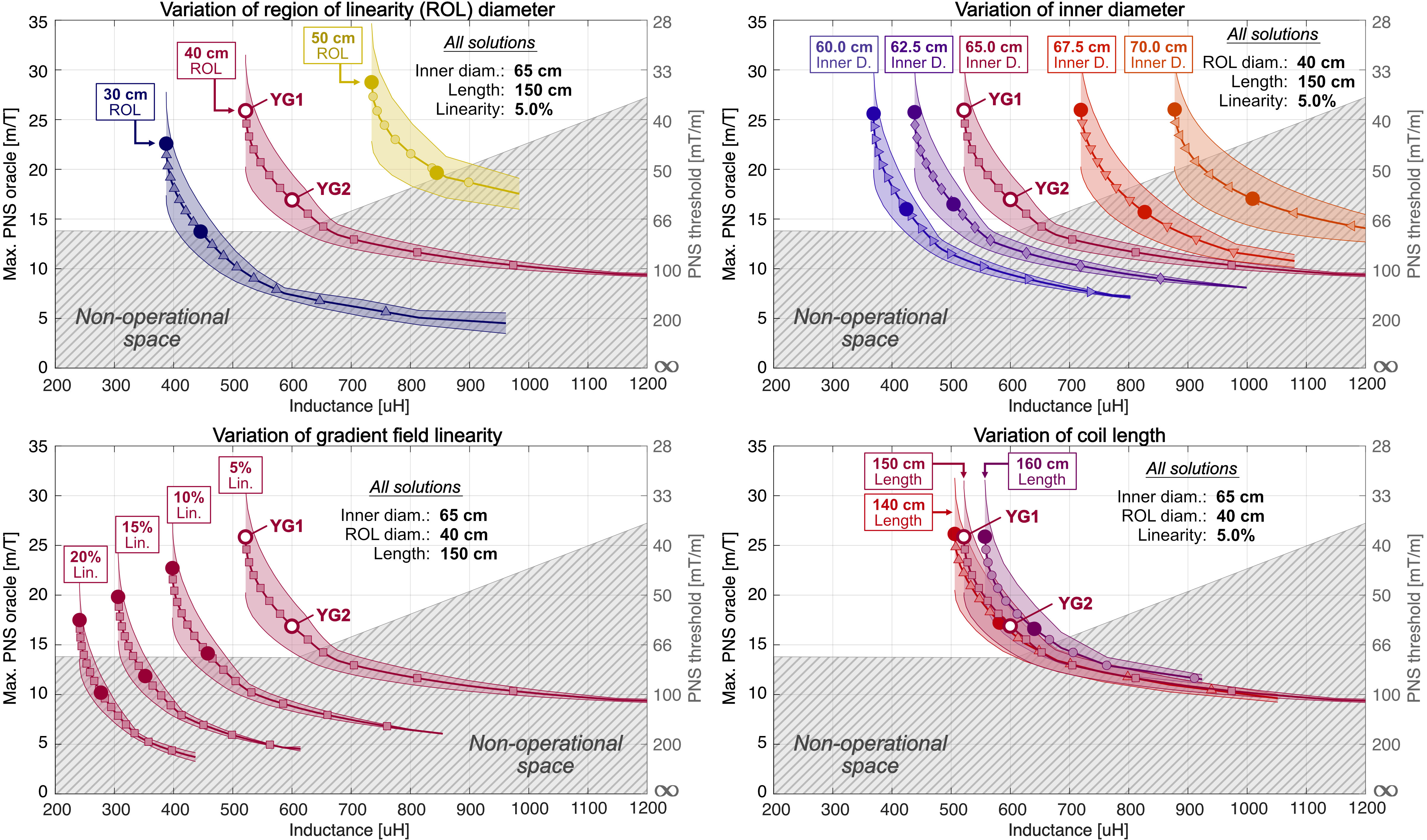
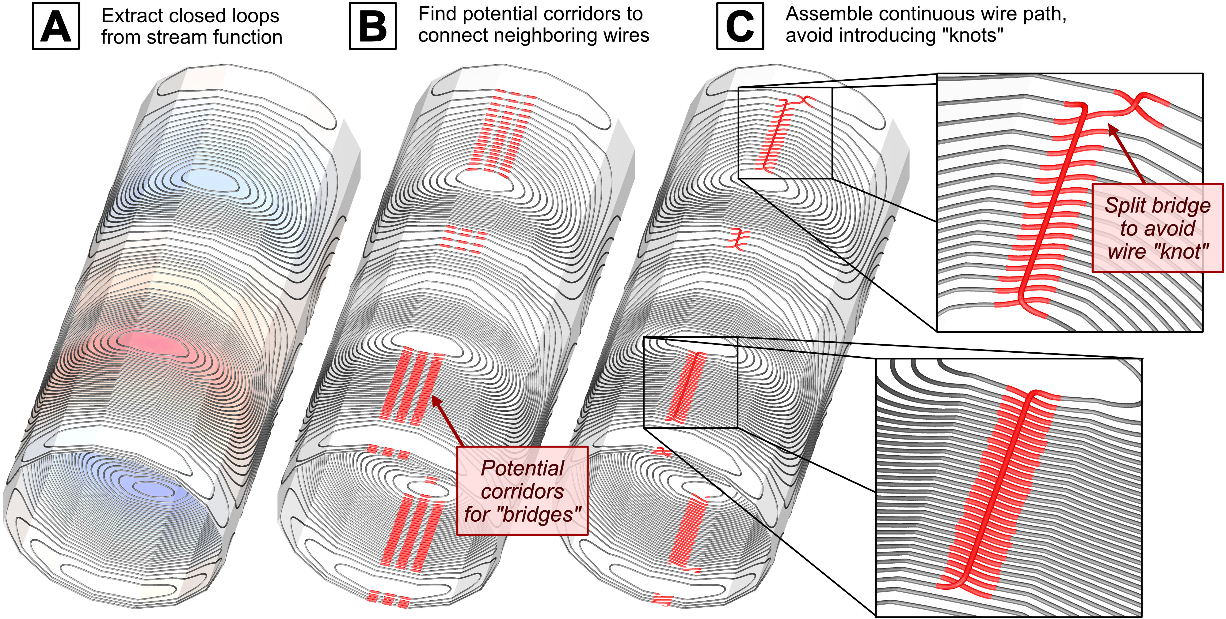
Choice of coil designs: We design two optimized Y-axis gradient coils (YG1 and YG2) using the framework recently presented [4]: YG2 is designed with a PNS constraint and 15% inductance penalty while YG1 is a conventional design without PNS optimization. The designs have otherwise identical constraints, and the windings are construction-ready with the goal of ultimately measuring and comparing PNS thresholds. Both coils are smaller diameter (lower inductance) than typical designs to ensure stimulation can be achieved in each case. The two coil designs were chosen by generating a family of L-curves analyzing the tradeoff between PNS oracle (reciprocal threshold) and coil inductance for a range of different coil characteristics (varying coil lengths, inner diameters, sizes of linear volumes, and field linearities). Other engineering constraints were kept constant: active shielding (≤ 0.5 μT/A on the cryostat surface), sensitivity (0.08 mT/m/A), linearity (≤ 5% deviation), FOV (40 cm diameter), force and torque balancing (≤ 0.4 N/A and ≤ 0.3 Nm/A) and wire spacing (≥ 8mm). The PNS optimization and analysis followed the previously described electromagnetic and neurodynamic modeling using a male and female body model [5-7]. All coils are designed for a polygonal rather than cylindrical coil geometry to simplify prototype construction.Generation of buildable wire pattern: Conversion of the stream function solution into a single continuous buildable wire path is considerably more complex for PNS optimized coils due to the twist in the winding pattern. We developed an algorithm to automatically generate buildable wire paths from the individual closed loops (Fig. 3). The windings are designed to be milled into ABS sheets with a CNC router, populated with AWG 8 wire, assembled to form the 16-sided polygonal coil former and covered with fiberglass/epoxy. Note that these coils are meant for PNS threshold measurements outside the magnet at low duty-cycle rather than for imaging.
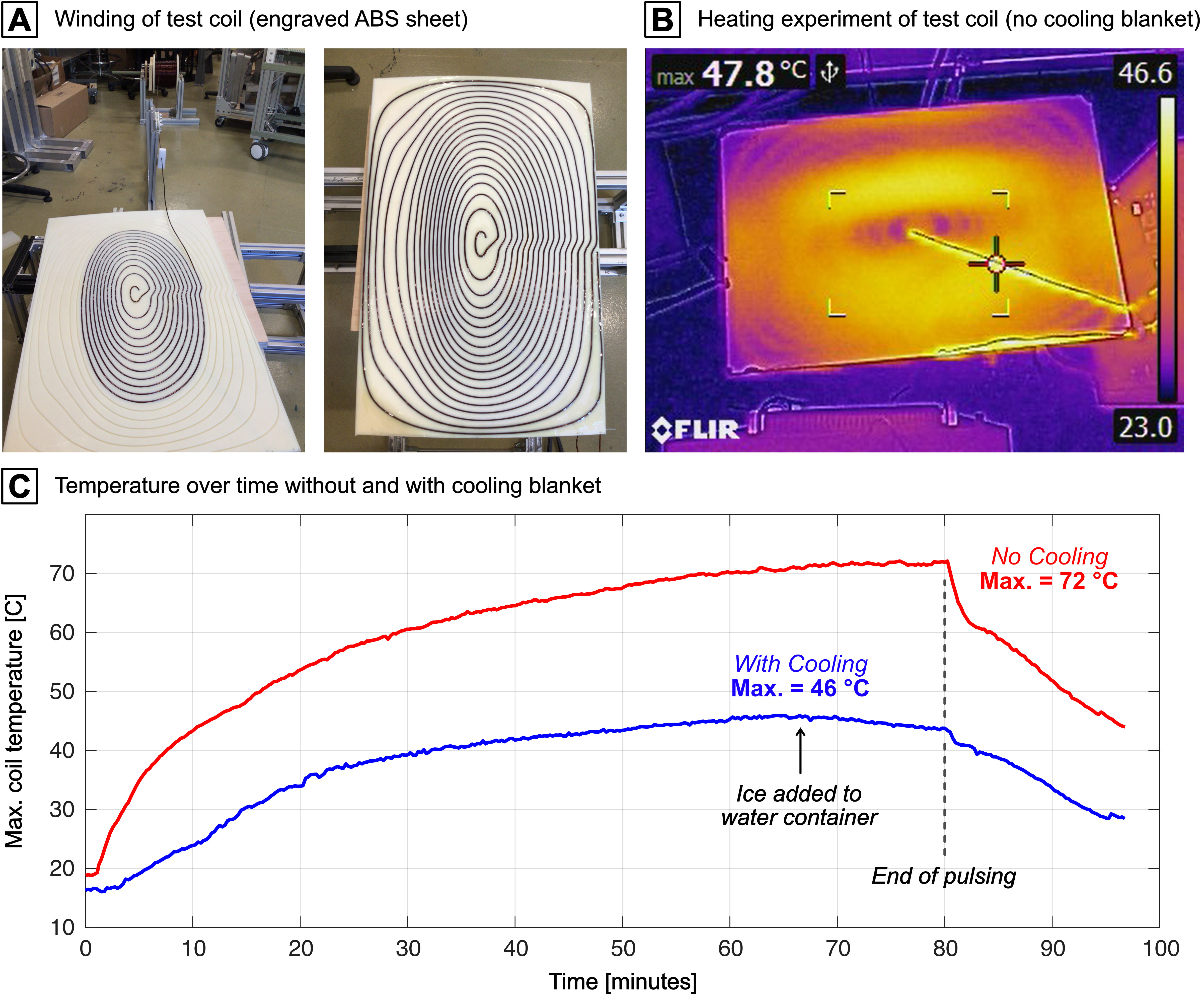
Heating test: We anticipate a heat generation of approx. 1.5 kW for typical trapezoidal waveforms used in threshold experiments. Cooling will be performed by wrapping the coil in water cooling blankets. We tested the feasibility of this approach on a smaller test coil (one fourth of the unoptimized coil YG1 primary). The coil was driven with a continuous 1 kHz sinusoid at 80A, which corresponds to 50 ms pulses at ~700A every 5 seconds (mimicking the stimulation experiments). The cooling blankets were placed on the wire side (i.e., at minimum distance to the wire), while we filmed the patient-facing side with an infra-red camera.
Results
Figure 1 shows L-curve trade-offs between PNS oracle (reciprocal threshold) and inductance. The shaded area of each L-curve denotes the span of the female/male PNS oracle, while the solid line (with markers) corresponds to the average of the two models. We found the average to be a good proxy for the population averages in previous studies [5,6]. The dashed gray shaded area corresponds to the performance space inaccessible due to the amplifier’s current/voltage limits (900A, 2200V). The different panels correspond to variations of a single coil design parameter. Coil solutions YG1 and YG2 achieve good balance between the four design parameters with a 51% increase in PNS thresholds (35% oracle reduction). Note that the PNS thresholds of the two coils and both models lie within the operational region which is critical for experimental validation.Figure 2 shows the PNS threshold curves of YG1 (black) and YG2 (red) for both model sexes (and their average). The gray dashed area corresponds to the performance space inaccessible to the amplifier. The blue dashed area corresponds to the performance gain resulting from 51% greater PNS thresholds of coil YG2; the yellow area shows the lost performance from the 15% inductance increase. Figure 2 also shows the final winding patterns and predicted nerve activation maps for YG1 and YG2.
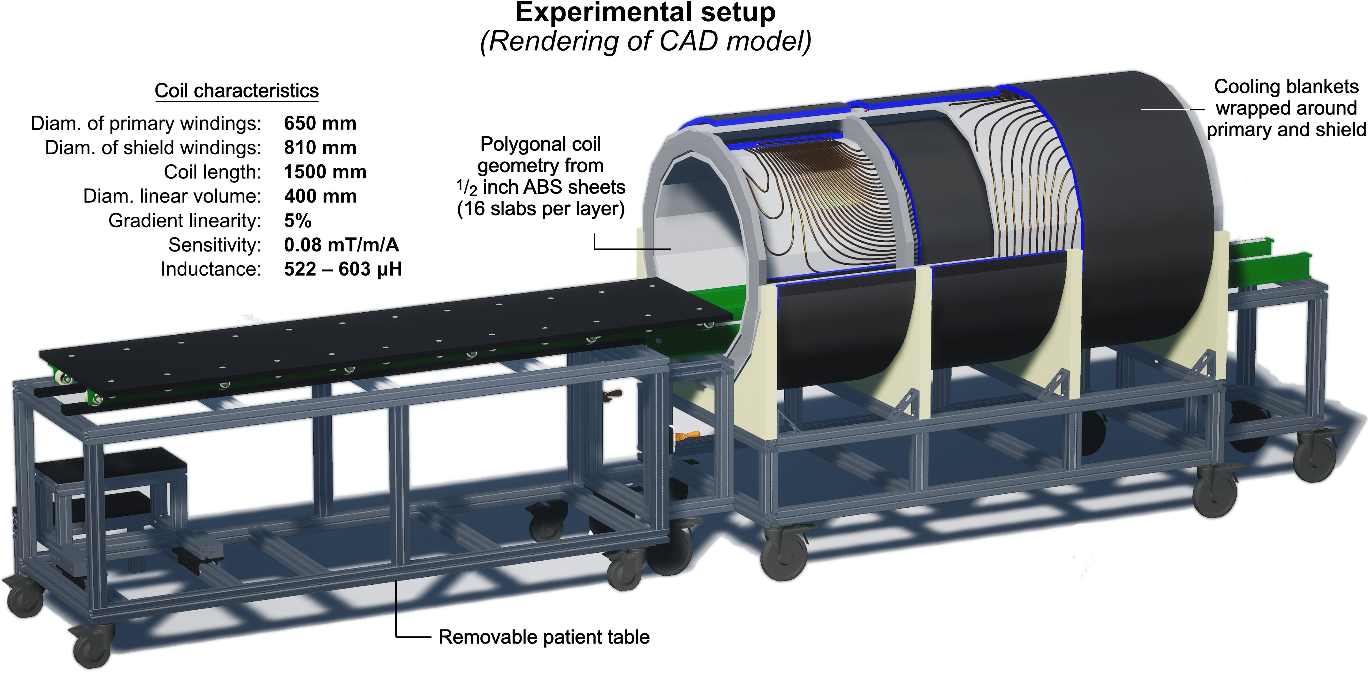
Figure 3 illustrates the workflow of converting the raw winding pattern (iso-contours of the stream function) into a single buildable coil pattern. Figure 4 shows the experimental setup (CAD design rendering).
Figure 5A/B show the test coil used in the heating experiment and an infra-red image of Ohmic heating. Figure 5C shows the temperature over time with and without cooling which reduced the max. temperature from 72 to 46 °C.
Conclusion
PNS constrained coil design enables studying trade-offs between nerve thresholds and conventional engineering metrics. This allowed us to identify two optimized designs YG1 and YG2, with the latter increasing PNS thresholds by 51% at a 15% inductance penalty. The coils were designed such that the PNS thresholds of both coils lie well within the operational parameter space to allow for experimental validation. Construction and experimental validation of these prototypes is on-going.Acknowledgements
The authors would like to acknowledge the help of past and present members of the gradient coil group at Siemens Healthineers, including Peter Dietz, Gudrun Ruyters, Axel vom Endt, Ralph Kimmlingen, Franz Hebrank, and Eva Eberlein. Research reported in this publication was supported by the National Institute of Biomedical Imaging and Bioengineering, and the National Institute for Mental Health of the National Institutes of Health under award numbers R24MH106053, U01EB026996, U01EB025162, U01EB025121, R01EB028250. The content is solely the responsibility of the authors and does not necessarily represent the official views of the National Institutes of Health.References
[1] Setsompop et al., “Pushing the limits of in vivo diffusion MRI for the human connectome project”, NeuroImage, vol. 80, pp. 220 – 233, 2013
[2] McNab et al., “The human connectome project and beyond: Initial applications of 300 mT/m gradients”, NeuroImage, vol. 80, pp. 234 – 245, 2013
[3] Tan et al., “Peripheral nerve stimulation limits of a high amplitude and slew rate magnetic field gradient coil for neuroimaging”, Magnetic Resonance in Medicine, vol. 83, no. 1, pp. 352–366, 2020.
[4] Davids et al., “Optimization of MRI Gradient Coils with Explicit Peripheral Nerve Stimulation Constraints”, IEEE Transactions on Medical Imaging, 2020, 40, 129-142
[5] Davids et al. “Predicting magnetostimulation thresholds in the peripheral nervous system using realistic body models", Scientific Reports, vol. 7, no. 1, p. 5316, 2017.
[6] Davids et al. "Prediction of peripheral nerve stimulation thresholds of MRI gradient coils using coupled electromagnetic and neurodynamic simulations", Magnetic resonance in medicine 81.1 (2019): 686-701.
[7] Davids et al., “A Huygens’ surface approach to rapid characterization of Peripheral Nerve Stimulation”, Magnetic Resonance in Medicine, 2021, in press
Figures