1368
Z-Gradient Array Coil Equipped with a Tunable Shield Array for Creating Multiple-Imaging Volumes
Manouchehr Takrimi1 and Ergin Atalar2
1National Magnetic Resonance Research Center, Bilkent University, Ankara, Turkey, 2Department of Electrical and Electronics Engineering, Bilkent University, Ankara, Turkey
1National Magnetic Resonance Research Center, Bilkent University, Ankara, Turkey, 2Department of Electrical and Electronics Engineering, Bilkent University, Ankara, Turkey
Synopsis
A z-gradient array coil equipped with a tunable shield array is proposed to achieve multiple imaging volumes that can be shifted along the coil axis. This is achieved by a set of independently tunable power amplifiers that feed the array elements. The proposed array dynamically provides a proper shield for the main array in which its magnetic profile can be adjusted on the fly. Five multiple-region magnetic profiles are simulated to demonstrate the flexibility of the proposed array: (a) a double-gradient profile; (b) shifted version of (a); (c) highly linear double-gradient profile without shielding; (d) triple-gradient profile; (e) quintuple-gradient profile.
Purpose
A set of independently tunable arrays can replace the conventional gradient coils and their active shields. It makes the gradient system highly customizable and offers a broader range of features in addition to the currently available traditional functionalities.Method
Gradient arrays have been used for different applications such as shimming1-2, field profiling without shielding3-6, self-shielded7-8 field profiling, and multiple volume imaging9-11. As a proof of concept, we recently proposed a 24-element active-shield z-gradient array12-13 fed by digitally tunable independent power amplifiers14. Based on a combinational scenario of analytical and numerical optimizations, a proper set of feeding waveforms of 100A maximum is calculated to achieve a programmable magnetic field profile within the imaging volume(s). It is possible to vary different performance parameters, including the gradient intensity, size and position of the ROI(s), linearity error, shielding effectiveness, and the slew rate. The optimization toolbox for MapleTM 2018 software is deployed to carry out the optimizations.Results
Figure 1(a) shows the cross-section view of the proposed z-gradient array consisting of 12 pairs of wire bundles, each with ten copper wires. Physical dimensions are given in the caption. A 10mm thick aluminum cylindrical shell of 90cm diameter and 80cm height has been inserted in the simulations to include the effect of induced eddy currents within the warm cryostat. All feeding waveforms are trapezoidal with 100μs rise, fall, and plateau times. For shielding effectiveness assessment, we define “residual eddy current” (REC) as the $$$\it{B_Z}$$$ field ratio 20μs after to 20μs before the fall-time in an appropriate point within the ROI(s). Additionally, the linearity error is calculated by the maximum field deviation about the ideal field normalized to the maximum ideal field within the ROI(s). The numerical simulations are based on Ansys Maxwell 2019.R1.Starting with double ROI, Fig. 2(a) shows a half cross-section view of the logarithmic magnitude plot of the $$$\overline{B}$$$ field for the proposed array at t=100μs (at the end of the plateau). The cryostat, both ROIs at $$$\pm7$$$cm, the primary and shield arrays, and the surrounding fields are visible. Fig. 2(b) shows another half-plot simulation where the same ROIs are shifted by 2cm along the coil axis. To see more details clearly, Fig. 3(a) and (b) show the corresponding magnified $$$\it{B_Z}$$$ field map around the arrays and within the ROIs. The maximum RMS current for all array elements are 42.0A and 78.6A, and the maximum induced voltages across the elements are 38.2V and 42.3V, respectively. The ROI diameter, average linearity error, average gradient strength, and REC are 100mm, 24.5%, 62.7mT/m, and less than $$$2.4\times10^{-4}$$$%, respectively.
By sacrificing the shielding effectiveness and 16% of the gradient, six times higher linearity is achieved. Figure 4(a) shows the modified double gradient profile with 100mm, 4.0%, 50mT/m, and $$$1.5\times10^{-2}$$$% as the relevant parameters. The maximum RMS current and induced voltages are 82.7A and 52.4V, respectively. Since the field interaction with the cryostat is increased, the REC is about 100 times higher, as shown by the $$$\overline{B}$$$ field’s logarithmic magnitude plot for the half gradient in Fig. 4(b).
Figure 5(a) shows the $$$\it{B_Z}$$$ field map of the fourth configuration consisting of three 60mm diameter ROIs along the coil axis. The linearity error is less than 25.7% and the average gradient strengths at the center of three ROIs are $$$\pm60$$$mT/m at $$$z=0,z=\pm8$$$cm, respectively. The REC is about $$$1.0\times10^{-4}$$$%, while the maximum RMS current and induced voltages are 81.2A and 48.5V, respectively.
Figure 5(b) shows five ROIs with 7cm intervals. The average gradient strengths are $$$\pm22.4$$$mT/m at $$$z=0,\pm7$$$cm and 20.0mT/m at $$$z=\pm14$$$cm. The diameter and linearity error for five ROIs are 50 mm and less than 27%, respectively. The REC is about $$$8.8\times10^{-4}$$$%, which is 4 to 8 times higher than the previous shielded cases. The maximum RMS current and induced voltages are 87.6A and 43.7V, respectively.
Discussion
In conventional gradient coil design, the wire positions are optimized to satisfy linearity, efficiency, gradient strength, shielding, and other performance constraints. Also, the whole coil is fed by an expensive yet powerful amplifier to supply enough power for both coils connected in series. After construction, only the feeding waveform can be adjusted to fine-tune the gradient assembly. In the proposed tunable array-based design, less expensive but independent power amplifiers supply an optimized set of 24 feeding waveforms to satisfy the constraints. Five case studies are simulated to show its flexibility in changing the magnetic field profile on the fly. In addition to different capabilities12-13 discussed earlier, it is possible to generate multiple imaging volumes for parallel imaging in MRI.Conclusion
The benefit of deploying the array configuration designing gradient coils is fourfold: (a) It is highly flexible and fully customizable, even for nonlinear profiles; (b) It speeds up the imaging process since the impedance of the individual array elements is less than the conventional coils; (c) Unprecedented magnetic field profiling is possible for a broader range of MRI applications; (d) If shielding is not concerned, both arrays may be used to achieve more sophisticated field profiles; (e) It can be used to generate nonlinear field profiles. We expect these proof-of-concept simulations to be verified by field measurements using the implemented coils.Acknowledgements
No acknowledgement found.References
- Juchem, Christoph, Terence W. Nixon, Scott McIntyre, Vincent O. Boer, Douglas L. Rothman, and Robin A. de Graaf. "Dynamic multi-coil shimming of the human brain at 7 T," J. Magn. Reson., vol. 212, no. 2 (2011): 280-288.
- Juchem, Christoph, Terence W. Nixon, Scott McIntyre, Douglas L. Rothman, and Robin A. de Graaf. "Magnetic field homogenization of the human prefrontal cortex with a set of localized electrical coils," Magn. Reson. Med., vol. 63, no. 1 (2010): 171-180.
- Juchem, C., Green, D., de Graaf, R. A. Nov. 2013. “Multi-coil magnetic field modeling,” J. Magn. Reson., vol. 236, pp. 95-104.
- Taraghinia, Soheil (2016). A z-gradient coil array system for magnetic resonance imaging (Master’s thesis). Retrieved from http://hdl.handle.net/11693/28988
- Ertan, Niyazi Koray (2019). Design and applications of a z-gradient array in magnetic resonance imaging (Ph.D. dissertation). Retrieved from http://hdl.handle.net/11693/48231
- Jia, F., Schultz, G., Testud, F. et al. “Performance evaluation of matrix gradient coils,” Magn. Reson. Mater. Phy. 29, 59–73 (2016).
- Jia, F., Littin, S. et al. Aug. 2017. “Design of a shielded coil element of a matrix gradient coil,” J. Magn. Reson., vol. 281, pp. 217-228.
- S. Littin, et al., “Development and implementation of an 84-channel matrix gradient coil,” Magn. Reson. Med.,vol. 79, no. 2, pp. 1181-1191, Feb. 2018.
- Parker, D.L. and Hadley, J.R. (2006), Multiple-region gradient arrays for extended field of view, increased performance, and reduced nerve stimulation in magnetic resonance imaging. Magn. Reson. Med., 56: 1251-1260. https://doi.org/10.1002/mrm.21063
- Goodrich KC, Hadley JR, Moon SM, et al. Design, Fabrication and Testing of an Insertable Double-Imaging-Region Gradient Coil. Concepts Magn Reson Part B Magn Reson Eng. 2009; 35B(2): 98-105. doi:10.1002/cmr.b.20138
- Ertan, K., Taraghinia, S., Sadeghi, A. and Atalar, E. 2018. “A z‐gradient array for simultaneous multi‐slice excitation with a single‐band RF pulse,” Magn. Reson. Med., vol. 80, pp. 400-412.
- Takrimi, M. and Atalar, E., “A Programmable Set of Z-Gradient Array and Active-Shield Array for Magnetic Resonance Imaging”, ISMRM, Virtual, 2020.
- M. Takrimi, and E. Atalar, “MRI Hybrid Gradient Coil Equipped with a Programmable Z-Array and Conventional X- and Y- Elements”, ISMRM, Virtual, 2021.
- Babaloo, R., Taraghinia, S., Acikel, V., Takrimi, M. and Atalar, E., “Digital Feedback Design for Mutual Coupling Compensation in Gradient Array System”, ISMRM, Virtual, 2020.
Figures
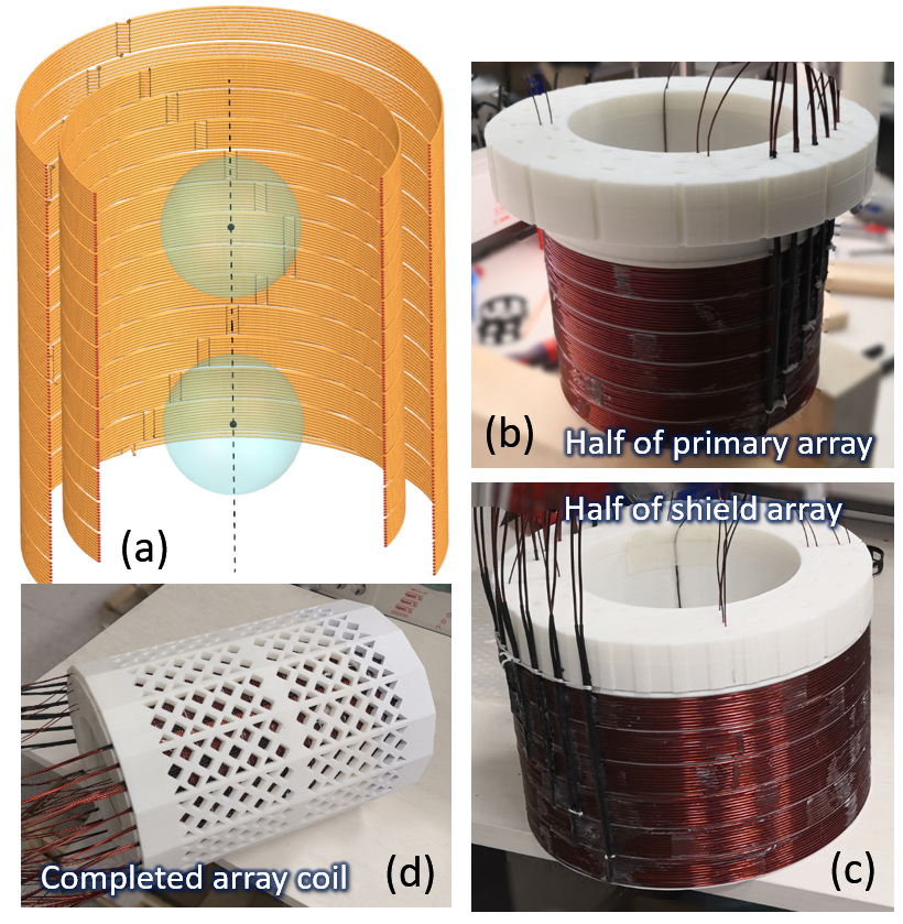
Fig. 1: (a) The longitudinal partial cross-section of the proposed z-gradient array consists of two sets of 12 wire bundles, each with 10 series-connected copper wires of 2 mm diameter. The diameter/height of the primary and the shield array coils are 24/30 and 30/35 cm, respectively. Two spherical ROIs of 10 cm diameter located at ±7 cm are shown. The aluminum warm cryostat and the wiring cables are not shown. Half of the constructed primary (a) and the shield (c) array coils using 3D-printed formers. (d) The completed array coil with a 3D-printed perforated housing ready for measurements.
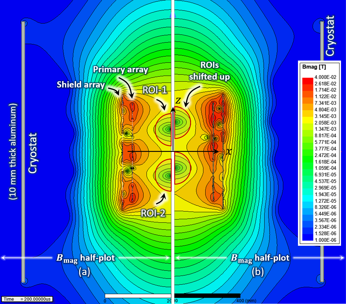
Fig. 2: Two half cross-section views of the proposed array that generate double ROI configurations: (a) Symmetric ROIs about the isocenter at ±7cm; (b) the same ROIs shifted up by 2cm. The logarithmic magnitude plot of the $$$\overline{B}$$$ field for both configurations are provided at t=200μs (at the end of the plateau). The cryostat, both ROIs, the primary and shield arrays, the surrounding fields around the arrays, and the stray fields are visible.
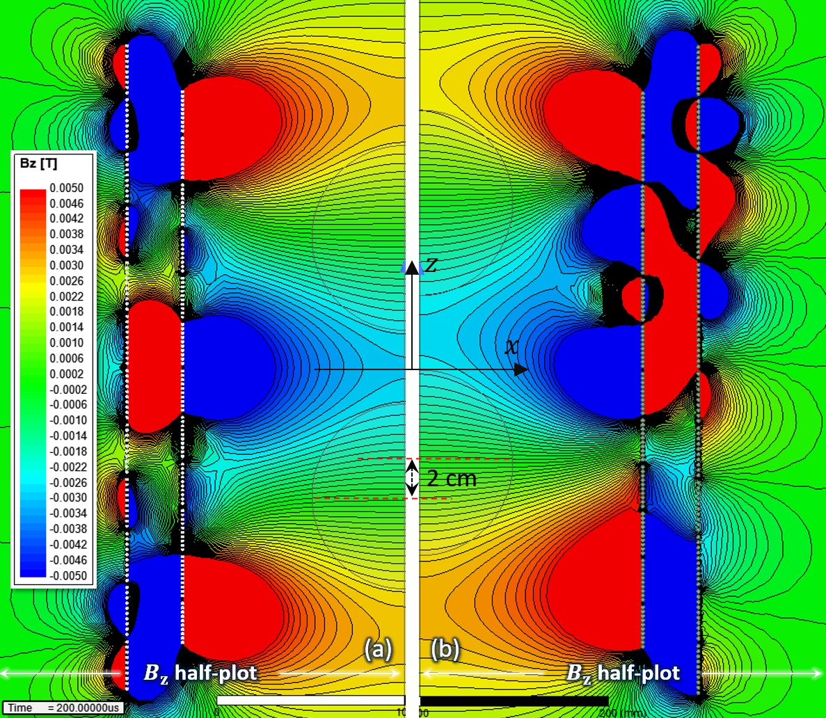
Fig. 3: Magnified versions of Fig. 2 that show the corresponding BZ field map within the ROIs with 0.2mT contour lines. The cryostat is not shown for better magnification. (a) For two symmetric ROIs at ±7cm, the diameter, linearity error, maximum gradient strength, and REC are 100mm, 23.0%, 63mT/m, and less than $$$2.4\times10^{-4}$$$%, respectively. The maximum RMS current is 42.0A. (b) For the shifted version of (a) by 2cm along the coil axis, the performance parameters are 100 mm, 24.8%, 62.3mT/m, and $$$2.3\times10^{-4}$$$% %, respectively. The RMS current is increased to 78.6 A.
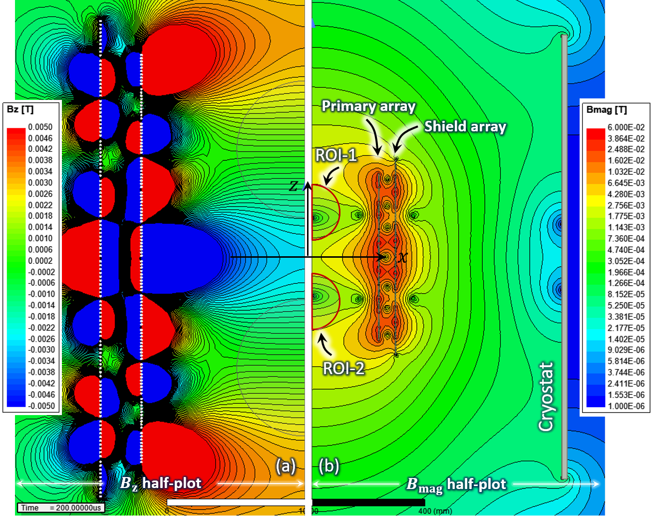
Fig. 4: A modified double ROI configuration similar to Fig. 3 with six times better linearity but without shielding and 16% less gradient strength. The diameter, linearity error, gradient strength, and REC of the ROIs are 100 mm, 4.0%, 50mT/m, and $$$1.5\times10^{-2}$$$%, respectively. The maximum RMS current and induced voltages are 82.7A and 52.4V, respectively. (b) The relevant magnitude half-plot of the magnetic field across the coil. High interaction between the field and the cryostat results in a 100 times higher REC value than the shielded configurations.
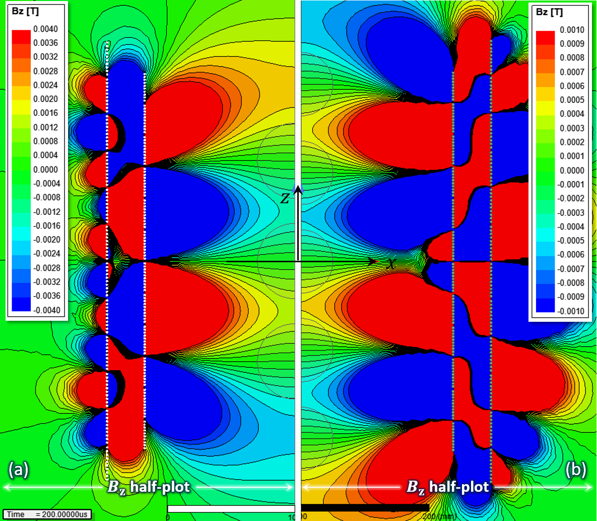
Fig. 5: BZ field maps for (a) three ROIs (0.2mT contours) and (b) five ROIs (0.1mT contours). (a) The gradients are 58.9mT/m at z=0 and -60.4mT/m at z=±8cm. The diameter, linearity error, and REC are 60mm, 25.7%, and $$$1.0\times10^{-4}$$$% respectively. The maximum RMS current and induced voltages are 81.2A and 48.5V, respectively. (b) The gradients are -22.2mT/m at z=0, 22.6mT/m at z=±7cm, and -20.0mT/m at z=±14cm. The diameter, linearity error, REC, maximum RMS current, and induced voltages are 50mm, between 23% and 27%, $$$8.8\times10^{-4}$$$%, 87.6A, and 43.7V, respectively.
DOI: https://doi.org/10.58530/2022/1368