1319
Impact of cardiac geometry segmentation on MRI-driven estimates of myocardial stiffness in an in vitro synthetic heart model1Radiology, Stanford University, Stanford, CA, United States, 2Radiology, Veterans Administration Health Care System, Palo Alto, CA, United States, 3Mechanical Engineering, Stanford University, Stanford, CA, United States, 4Biomechanical Engineering, Technische Universiteit Delft, Delft, Netherlands, 5Bioengineering, Stanford University, Stanford, CA, United States
Synopsis
MRI-driven computational constitutive modeling can be used to obtain subject-specific myocardial passive stiffness. Verifying the accuracy and precision of this technique requires overcoming the challenge of obtaining ground-truth in vivo myocardial stiffness. We developed a controllable in vitro diastolic filling setup which incorporates a soft heart phantom of known myocardium-mimicking mechanical stiffness and MRI properties. Using the setup we demonstrate that uncertainties in quantifying cardiac reference geometry can lead to errors in estimating myocardial passive stiffness. The in vitro setup is designed to enable us to achieve our overarching goal: to extensively validate in vivo MRI-based myocardial passive stiffness estimation.
Introduction
Increased passive stiffness of cardiac muscle (myocardium) contributes to reduced diastolic filling in heart failure with preserved ejection fraction (HFpEF) [1]. Hence, reliable clinical identification of altered passive myocardial stiffness could improve HFpEF management. Computational constitutive modeling using MRI, ventricular pressures, and finite element modeling (FEM) can be leveraged to estimate myocardial passive stiffness [2,3]. Although the patient-specific data needed to estimate stiffness (cardiac geometry, kinematics, microstructure, and boundary conditions) are unavoidably subject to uncertainty, quantifying the accuracy of MRI-driven passive myocardial stiffness estimates is understudied due to lack of ground-truth in vivo myocardial tissue properties.We address this validation challenge using soft, MRI-visible heart phantoms of known stiffness that are incorporated within an in vitro flow loop. The objective of this study was to examine the effect of errors in MRI-derived cardiac geometry on simulated myocardial passive stiffness. We compared phantom-derived material stiffness using the geometry from which the phantom was developed (model-A) and an alternate geometry from segmented phantom MRI (model-B) to an independently measured ground-truth.
Methods
Phantom DevelopmentHigh-resolution T1-weighted images (Fig.1) from a healthy ex vivo porcine heart (geometrically restored to in vivo mid-diastasis geometry) [4] were segmented (MITK workbench) to generate a geometric model (model-A) of the heart. The model was modified (Fusion 360, Autodesk) to incorporate ventricular ports and an apical anchor. Stereolithography files of the left and right ventricular (LV and RV) blood pools and the mold defining the epicardial surface were 3D printed with water-soluble polyvinyl acid and polylactic acid, respectively. The heart phantom was cast with a blend of 1:4 Sylgard184:Sylgard527 (Dow Corning) using lost-wax casting [5].
Phantom Material Ground-truth Stiffness
Ground-truth stiffness of the phantom material was measured with uniaxial tensile testing. Samples of uniform width (12mm) were cut from cured sheets of even thickness (3mm) and three samples were mechanically tested [6] using an Instron 5944 Microtester.
The ground truth material parameters were obtained by nonlinear regression using the experimentally derived principal Cauchy stress and stretch. MRI relaxation properties of the Sylgard blend has been measured in previous work [7].
Ventricular Filling Setup
The heart phantom was embedded within a flow loop (Fig.1) controlled by an MRI-compatible flow pump (CardioFlow 5000 MR, Shelley Medical Imaging Technologies) programmed to simulate in vivo diastolic LV filling (sinusoidal flow, 1s period). MRI-compatible pressure transducers (Micro-Tip SPR 350S, Millar) in the LV and RV cavities enabled acquisition of filling pressures in PowerLab (ADInstruments). The phantom was fixed at the apex and basal ports to create reproducible boundary conditions for the simulation.
Imaging Methods: reference geometry and injected volume estimation
All in vitro images were collected on a 3T (Skyra, Siemens). The phantom’s reference geometry was acquired using a 3D spoiled gradient recalled echo (3D SPGR; TE/TR=2.17/5.5ms; FA=20º; isotropic 1.00mm3; static equilibrium phase), performed over the entire volume. CINE Balanced Steady-State Free Precession (bSSFP) images were acquired during filling to capture phantom motion.
3D SPGR images of the phantom reference configuration were semi-automatically segmented (MITK workbench) to obtain the geometry (model-B) used for in silico modeling. The filling volume was obtained from the CINE bSSFP images of the phantom during inflation (Fig. 2). The synced pressure and filling volume were used to obtain the LV pressure-volume relation used for stiffness estimation.
In silico modeling and stiffness quantification
The 3D geometric model of the phantom in the reference configuration was used to generate a volumetric quadratic tetrahedral mesh of average edge size 2mm (GMSH). Studies characterizing Sylgard show that it is nearly incompressible (ν=0.495) [9], so we enforced this in the simulation.
Diastolic filling was simulated by applying a pressure boundary condition to the LV and RV, and the resulting phantom LV volumes were recorded. The experimentally derived LV pressure-volume relation was used to inversely estimate the phantom's material stiffness. More specifically, we iteratively updated to model’s underlying Mooney-Rivlin constitutive parameters (FEBio) to minimize the mismatch between the experimentally measured volume and the simulated pressure-induced volumetric expansion.
Results
The 3D models and tetrahedral mesh of model-A and model-B are shown (Fig.3). The peak filling volume was found to be 3.2 ml. We report the ground truth and simulated mechanical behavior, Mooney-Rivlin (constitutive relation) parameters and the tangent modulus (stiffness) at peak stretch (Fig.4). From the resulting simulated LV pressure-volume relation (Fig.5), we see that the simulated and target peak injected volume coincide. Model-A provides a stiffness estimate that is 9.9% less, whereas model-B provides a 25.5% less stiff estimate.Discussion
The stiffness simulated using model-B differs more from the ground-truth stiffness than model-A (Fig.4). Although model-A and model-B (Fig.3) are qualitatively similar, segmentation errors, particularly at the base and apex, appreciably affect the simulated stiffness. Refinement of the segmentation procedure could improve the accuracy of the stiffness estimate.In the future, we can manufacture phantoms of varying stiffness [8] and different geometries using the procedure described above. We will use phantoms of varying stiffnesses and geometries to achieve our overarching goal: to validate in vivo MRI-based myocardial passive stiffness estimation.
Conclusion
This work used subject-specific, soft heart phantoms to demonstrate that uncertainties in quantifying cardiac reference geometry can lead to errors in MRI-driven myocardial passive stiffness estimates.Acknowledgements
Project support: NIH R01 HL131823 to DBEReferences
1. Zile, M.R., Baicu, C.F., Gaasch, W.H., 2004. Diastolic Heart Failure — Abnormalities in Active Relaxation and Passive Stiffness of the Left Ventricle. New England Journal of Medicine 350, 1953–1959. https://doi.org/10.1056/NEJMoa032566
2. Røe, Å.T., Aronsen, J.M., Skårdal, K., Hamdani, N., Linke, W.A., Danielsen, H.E., Sejersted, O.M., Sjaastad, I., Louch, W.E., 2017. Increased passive stiffness promotes diastolic dysfunction despite improved Ca2+ handling during left ventricular concentric hypertrophy. Cardiovascular Research 113, 1161–1172.
https://doi.org/10.1093/cvr/cvx087
3. Peirlinck, M., Costabal, F.S., Yao, J., Guccione, J.M., Tripathy, S., Wang, Y., Ozturk, D., Segars, P., Morrison, T.M., Levine, S., Kuhl, E., 2021. Precision medicine in human heart modeling: Perspectives, challenges, and opportunities. Biomech Model Mechanobiol 20, 803–831. https://doi.org/10.1007/s10237-021-01421-z
4. Wang, V.Y., Nielsen, P.M.F., Nash, M.P., 2015. Image-Based Predictive Modeling of Heart Mechanics. Annual Review of Biomedical Engineering 17, 351–383. https://doi.org/10.1146/annurev-bioeng-071114-040609
5. Cork, T.E., Perotti, L.E., Verzhbinsky, I.A., Loecher, M., Ennis, D.B., 2019. High-Resolution Ex Vivo Microstructural MRI After Restoring Ventricular Geometry via 3D Printing, in: Coudière, Y., Ozenne, V., Vigmond, E., Zemzemi, N. (Eds.), Functional Imaging and Modeling of the Heart, Lecture Notes in Computer Science. Springer International Publishing, Cham, pp. 177–186. https://doi.org/10.1007/978-3-030-21949-9_20
6. Dual, S.A., Zimmermann, J.M., Neuenschwander, J., Cohrs, N.H., Solowjowa, N., Stark, W.J., Meboldt, M., Schmid Daners, M., 2019. Ultrasonic sensor concept to fit a ventricular assist device cannula evaluated using geometrically accurate heart phantoms. Artif Organs 43, 467–477. https://doi.org/10.1111/aor.13379
7. ASTM Standard D412, 1935 (2016), " Standard Test Methods for Vulcanized Rubber and Thermoplastic Elastomers—Tension" ASTM International, West Conshohocken, PA, 2016, DOI:10.1520/D0412-16, www.astm.org.
8. Kolawole, F.O., Peirlinck, M., Cork, T.E., Wang, V.Y., Dual, S.A., Levenston, M.E., Kuhl, E., Ennis, D.B., 2021. A Framework for Evaluating Myocardial Stiffness Using 3D-Printed Heart Phantoms, in: Ennis, D.B., Perotti, L.E., Wang, V.Y. (Eds.), Functional Imaging and Modeling of the Heart, Lecture Notes in Computer Science. Springer International Publishing, Cham, pp. 305–314. https://doi.org/10.1007/978-3-030-78710-3_30
9. Schneider, F., Draheim, J., Kamberger, R., Wallrabe, U., 2009. Process and material properties of polydimethylsiloxane (PDMS) for Optical MEMS. Sensors and Actuators A: Physical 151, 95–99. https://doi.org/10.1016/j.sna.2009.01.026
Figures
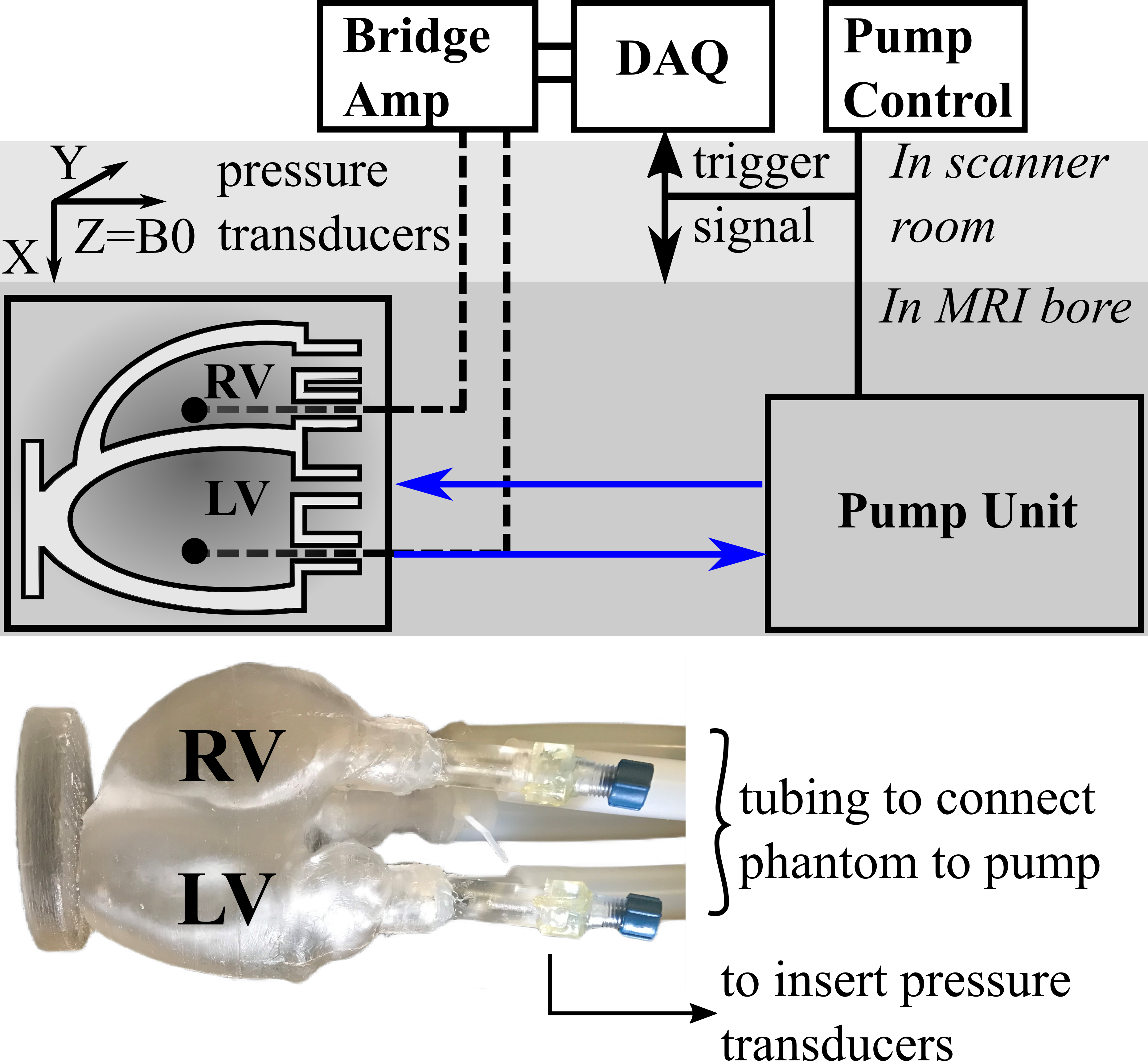
Fig. 1: Schematic of the experimental setup with heart phantom highlighted.
Fig. 2: Comparison of subject ex vivo GRE (geometrically restored to in vivo), and in vitro (phantom) 3D SPGR images after landmark-based rigid registration (a) short-axis ex vivo (b) short-axis in vitro (c) short-axis in vitro overlayed over ex vivo. The alignment of the ex vivo, and in vitro hearts is very high (d) short axis slice of in vitro cine bSSFP used to calculate the injected volume
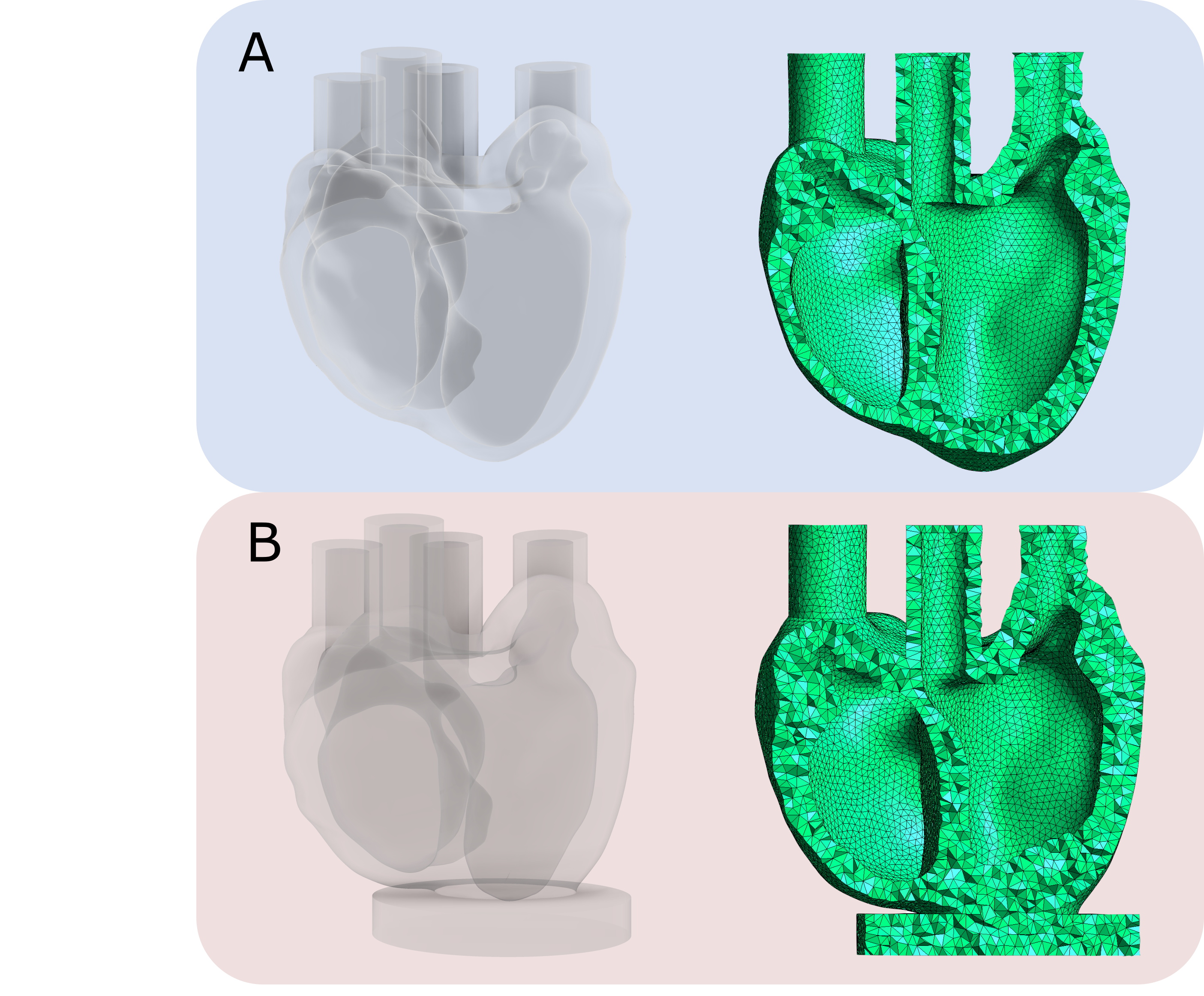
Fig. 3: Model-A – input geometry from which the phantom was developed. Model-B – geometry from the segmented phantom MRI images
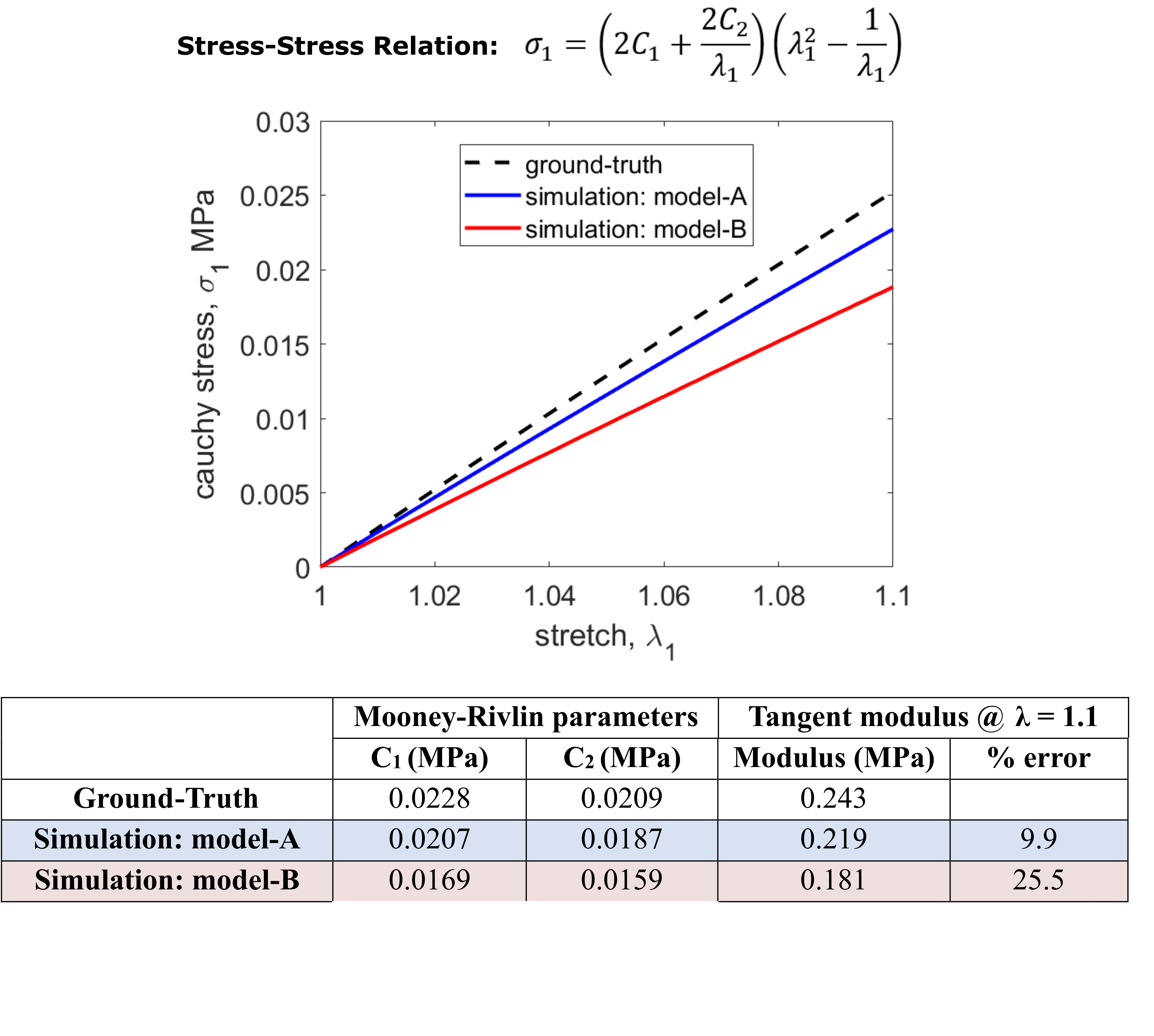
Fig 4: Comparison between ground truth and simulation results. Model-A refers to the input geometry from which the phantom was developed, and model-B refers to the geometry from the segmented phantom MRI images. Constitutive relation in uniaxial tension, relating principal Cauchy stress, σ1, and stretch, λ1. C1 and C2 are Mooney-Rivlin material parameters.
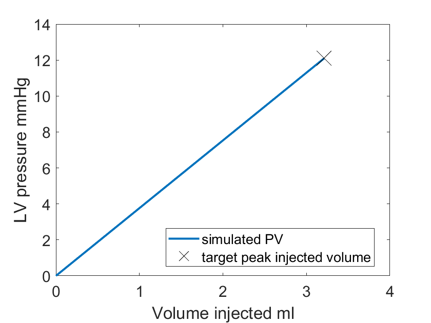
Fig. 5: Target LV pressure-volume and simulation LV pressure-volume. The simulated and target peak injected volume coincide.