1290
MRI compatibility for a novel simultaneous PET/MRI system with scintillator-based RF shielding for preclinical 7 T MRI scanner1Department of Physics of Molecular Imaging Systems, Institute of Experimental Molecular Imaging, RWTH Aachen University, Aachen, Germany, 2Hyperion Hybrid Imaging Systems GmbH, Aachen, Germany, 3Physics Institute III B, RWTH Aachen University, Aachen, Germany, 4Fraunhofer Institute for Digital Medicine MEVIS, Aachen, Germany
Synopsis
We present a preclinical PET/MRI system with highly-integrated PET modules in which the RF shielding is implemented on scintillator level for a 7 T Bruker BioSpec 70/20. The PET system's RF housing size is minimized by excluding parts of the scintillator while maintaining the RF shielding properties through the scintillator-integrated shielding. The modules are mounted inside the MRI coil, between resonator and RF screen. MRI compatibility is evaluated in a mouse phantom by means of spurious noise scans and SNR evaluations of standard morphologic sequences, while the PET system is off, idle and measuring. Additionally, postmortem mouse images are presented.
Introduction
In the scope of pushing the integration of positron emission tomography (PET) and magnetic resonance imaging (MRI) systems to the next level, it is crucial to evaluate radio frequency (RF) shielding concepts that allow a reduction of the PET system's RF housing size. This reduction can be achieved by selecting smaller scintillators and optimizing the electronics and cooling thicknesses; an approach that is however limited and expected to affect the PET system performance. By excluding the scintillator from the PET system's RF housing, the housing size can be reduced and, thus, the volume occupied within the RF coil, without compromising the PET system performance.Previous works introduced the integration of optically transparent, non-magnetic RF shielding materials that are integrated between the scintillator and photodetector1,2, and shielding on scintillator level3.
In this work, we present our fully-assembled PET/MRI setup in which the PET modules benefit from a scintillator-based RF shielding and are directly integrated into the MRI's RF Tx/Rx coil, between the resonator and RF screen.
Materials
Following components are used for the MRI setup:- 7 T Bruker BioSpec 70/20 with a BGA12SHP gradient system
- Custom coil with 112/50 mm, outer/inner diameter, resonator length ~100 mm.
- reference array without integrated shielding
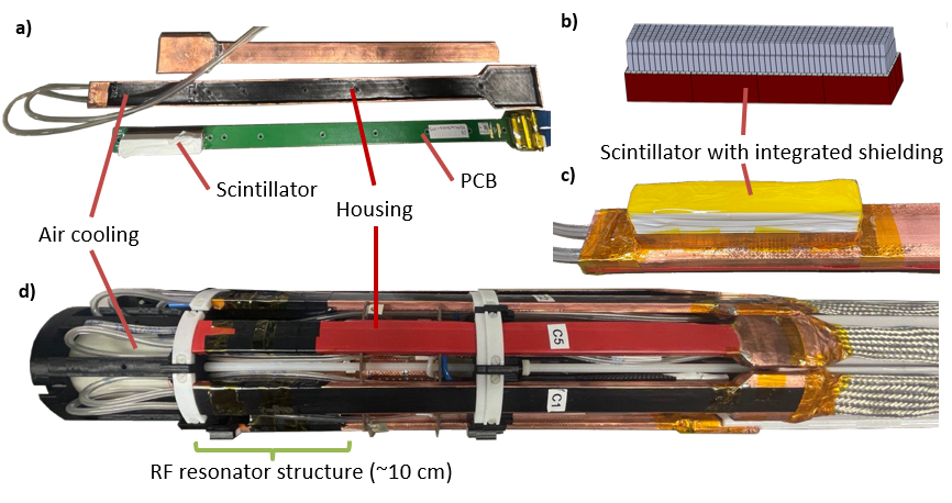
- array with integrated shielding, implemented by wrapping scintillator segments of the lowest scintillator layer (closest to photosensor) with copper foil (Figure 1b)).
- R4: four modules with reference scintillators
- C4: four modules with scintillator-level shielding
- C8: eight modules with scintillator-level shielding (Figure 1d))
Methods
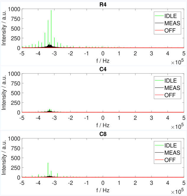
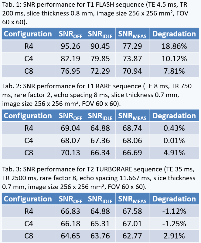
For each configuration, the coil is loaded with the phantoms and balanced using a network analyzer. The PET system is calibrated inside of the B0 field. All measurements are done for three PET states: off, idle, and measuring. Spurious signal scans are performed to acquire frequency spectra (bandwidth 1 MHz, spectral resolution 15.26 Hz/points) where f = 0 Hz corresponds to the 300 MHz resonance frequency. The resulting spectra are compared to investigate whether the noise emitted from the PET system electronics is coupling into the MRI receive chain. Additionally, we run standard morphological sequences for mouse imaging:- T1 FLASH
- T1 RARE
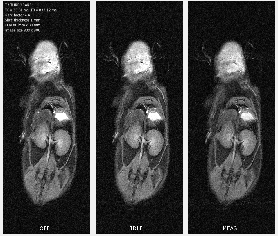
- T2 TURBORARE
Results
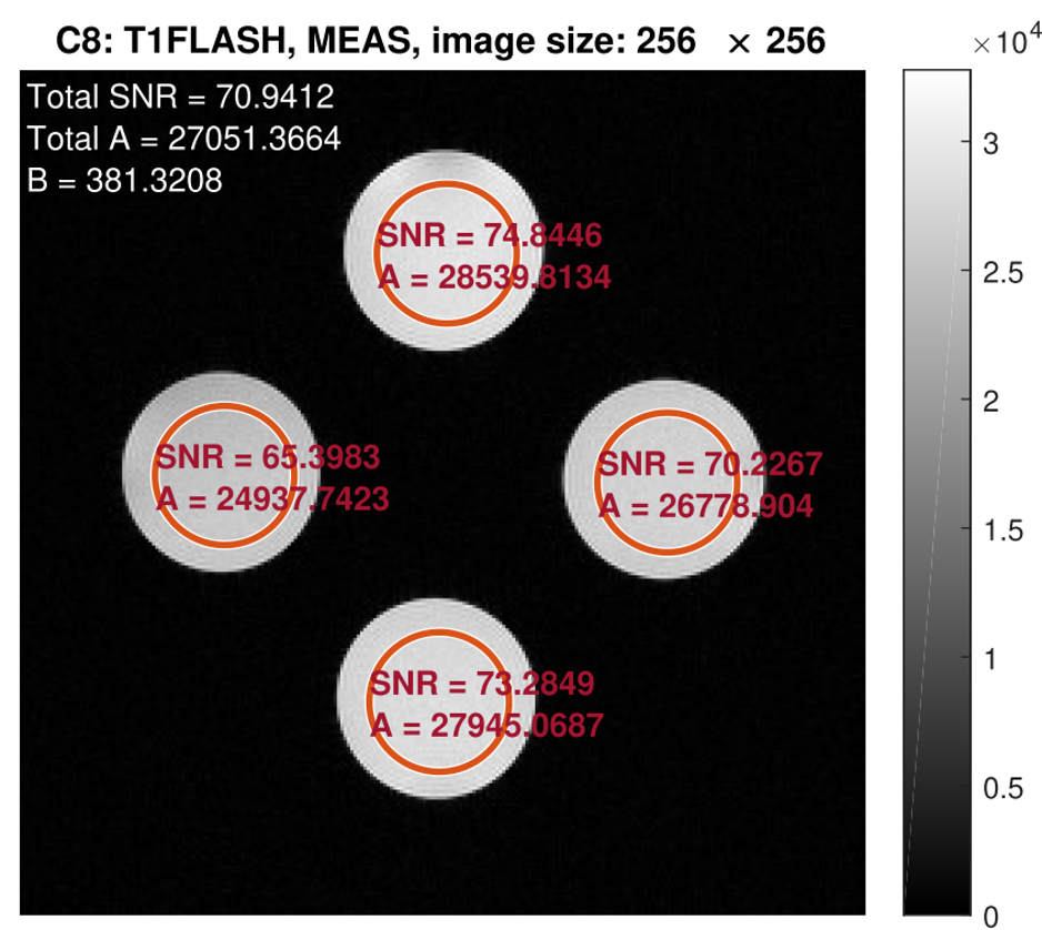
The spurious signal scans (Figure 3) showed increased noise at f = -0.33 MHz for both the idle and measuring state. Noise was prominent for the idle state in R4 and a decrease was achieved in C4 (from peak value 963.22 to 87.07). Noise during the measuring state was lower and also showed a decrease after introducing shielding. The strongest SNR degradation (Table 1-3) was seen for T1 FLASH. The SNR decreased by 18.86% for R4, 10.12% for C4, and 7.81% for C8. SNR in T1 RARE and T2 TURBORARE was less affected. The postmortem mouse images showed zipper artifacts for the idle state but not during PET measurements (Figure 4).Discussion
We observed a decreased noise in the spurious signal scans after introducing the shielding. The strongest SNR degradation was seen for T1 FLASH. However, phantoms were positioned off-center to accommodate for the radioactive sources, which may negatively affect the overall SNR level. Zipper artifacts were present in ex-vivo mouse images for the idle state only, while the measurement state resulted in a minor decrease in SNR. The same zipper artefacts were visible for the phantom measurements but not as prominent. Therefore, we recommend MRI measurements while the PET is off or measuring.Conclusion
We have presented MRI compatibility results for our novel PET/MRI coil with RF shielding integrated on the scintillator level, and modules integrated directly into the MRI coil. The MRI performance was not substantially impaired by the added shielding and we have shown that the tested FOV is large enough for total-body scans in mice.Acknowledgements
This project is funded by the German Research Foundation (DFG), project number 288267690.
We would like to thank Bruker BioSpin MRI GmbH, especially Dr. Thimo Hugger and the MRI RF development group, for enabling the assembly of the MRI coil in situ in Rheinstetten.
References
1. Yin, L., Schrank, F., Gross-Weege, N., Schug, D., & Schulz, V. (2021). RF shielding materials for highly-integrated PET/MRI systems. Physics in Medicine & Biology, 66(9), 09NT01.
2. Parl, C., Kolb, A., Schmid, A. M., Wehrl, et al. (2017). A novel optically transparent RF shielding for fully integrated PET/MRI systems. Physics in Medicine & Biology, 62(18), 7357.
3. Yin, L., Mueller, F., Kuhl, Y., Schrank, F., Schug, D., Schulz, V. (2019). Integrated RF shielding approach using semi-monolithic scintillators for PET/MRI systems. NSS/MIC conference 2019.
4. Yin, L., Gross-Weege, N., Nolte, T., Weissler, B., Radermacher, H., Schug, D., Nadig, V., Schulz, V. (2020). MRI compatibility assessment of an SiPM-based PET insert without RF shielding. NSS/MIC conference 2020.
5. PETsys Electronics SA. (Sept. 2018). TOFPET2 ASIC evaluation kit - hardware user guide (v1.3).
6. Gudbjartsson, H., & Patz, S. (1995). The Rician distribution of noisy MRI data. Magnetic resonance in medicine, 34(6), 910-914.
Figures