1288
Feasibility study of novel 8-channel stacked 1H/31P transceiver coil as PET insert for 7T MRI1UMC Utrecht, Utrecht, Netherlands, 2Eindhoven University of Technology, Eindhoven, Netherlands
Synopsis
The feasibility of simultaneous 1H/31P PET/MR imaging added-on to an existing 7T MRI system was assessed. Space constraints preclude using whole-body birdcages. Instead, an 8-channel 1H dipole array stacked with additional 8-31P channels is set up. By positioning PET detectors between the RF-shield and gradient coil, further shielding of the PET-crystals and electronics can be omitted. 8-channel 31P scans had a higher SNR compared to a birdcage setup. The 1H/31P setup gives ~5% degradation of PET sensitivity. Similarly, the impact of the new setup (proximity of the RF shield) was insignificant for MRI performance at both frequencies.
Introduction
Recently, the integration of a wide-bore 1.5T body birdcage in a PET system(1) was demonstrated but this is unfeasible for MR imaging for 1H at 7T due to the shortened wavelength. Alternatively, dipole-arrays have been popularly used for 1H imaging.31P-MRSI provides insight into the energy-metabolism and cell-proliferation and is thus invaluable for tumour characterisation. However, at low field strengths the low SNR necessitates large MRSI voxels in vivo. With the development of ultra-high field systems, in vivo 31P-spectroscopy is practicable (2).
However, the RF shield of the birdcage reduces the available room for PET detectors in the bore of the magnet.
The main goal of this study is to achieve simultaneous 7T 31P/1H and PET imaging, with PET detectors integrated into an existing 7T-MR system. Figure 1 demonstrates our current system. By positioning the PET detectors between the RF shield and the gradient coil, we can omit further shielding of the PET crystals and electronics to save space. Furthermore, we aim to use a dipole array consisting of eight 31P elements stacked onto the 1H elements for 1H/31P-MRSI, since a whole-body birdcage coil would limit the space for PET detectors.
We assess the effects of:
1)using an array of eight 31P/1H dipoles instead of a body birdcage coil on B1 and SNR for 31P
2)adding a RF shield at radius 29.5 cm on B1 at both frequencies, and
3)the presence of an array of eight 31P/1H elements on PET sensitivity
Methods
The PET performance is evaluated at our 7T system (Philips Achieva, Best, The Netherlands). The influence of the shield at both frequencies is simulated. Finally, the performance of a whole-body birdcage is compared to that of an 8-channel array for 31P at 7T in a scanner.MRI simulations
RF coil simulations (figure 2) were first performed in phantom for both the proton and the phosphorus coils in the presence of each other. The simulations are performed with the software Sim4Life (ZMT, Zurich, CH).For each frequency’s simulations, the ports of the elements for the other frequency are terminated by 50Ω. B1 maps are used to compare the influence of the presence of the shield on the array performance. The ports are then combined with a successively increasing phase of 45 degrees across all 8 elements to give CP performance. The simulations for B1+ are normalised to 1W of total input power to simplify comparison.
MRI-Scanner
For the 31P 7T phantom scans, identical sequences are used for both setups. The array is shimmed by means of custom-made cable-lengths to obtain optimal B1+ in the phosphorous-rich phantom voxel (contained within the larger 26L phantom). The SNR is evaluated for both setups for a matched flip-angle.
PET-Scanner
A cylindrical Ge-68 source (⌀20 cm, total activity: 34.1 MBq) was placed on the patient bed of a PET/CT system (Biograph mCT40, Siemens Healthcare, Erlangen, Germany) as in figure 1. Two 3-minute PET scans were made with a single bed position centered on the phantom: one with and one without the presence of the 1H/31P stacked setup. Data were obtained from the raw PET data in the Siemens acquisition console.
Results
MRI SimulationsThe presence of the shield has no appreciable influence on the performance of the 1H/31P array for either frequency, as shown in figures 3. for 1H and 4. for 31P.
Scanner
SNR comparison of shimmed 8-channel array (SNR of 233) and 31P birdcage (SNR of 126) from figure 5 shows that the B1 shimmed array outperforms the birdcage scanned.
PET Scanner
The total number of true coincidences obtained from the PET-scan of the cylindrical phantom with the stacked 1H/31P setup was 28321883, versus 29830146 without. This suggests that the PET sensitivity would be reduced by only ~5% when the current prototype array would be used for 1H/31P MRI/PET.
Discussion
Birdcage compared to array for 31P MRI performanceWhile the 8-channel 31P array seems to outperform the birdcage coil, it is to be noted that the array may require subject-specific-shimming. We performed this for the specific voxel containing the phantom. N.B. the strong non-uniformity of the 31P-field compared to 1H. It is conceivable that the flux is contained in the near-field of the elements and a further optimisation of the 31P elements may enhance B1+uniformity.
Effect of PET setup on MRI performance
The presence or absence of the shield shows insignificant changes in the B1 performance of the dipoles. However, with patients closer to the shield, the interaction is expected to increase.
Effect of MRI hardware on PET performance
A ~5% degradation for the PET sensitivity was observed when this novel 8-channel 1H/31P setup for MRI at 7T is placed inside an existing MR-PET system.
Conclusion
31P imaging can be performed with stacked elements, with an insignificant impact of the shield on the MRI performance for both frequencies. The impact of the array coils on the PET sensitivity was only a ~5% decrease. Using our design, obtaining 1H/31P MRSI and PET data is feasible for simultaneous 1H/31P MR-PET imaging at 7T.Acknowledgements
This project has received funding from the European Union’s Horizon 2020 research and innovation programme under grant agreement No 801075, 'NICI' and from the NWO’s Open Competition XS, packet 21-1 programme, file number OCENW.XS21.1.128
References
- Woutjan Branderhorst, Bart R. Steensma, Casper Beijst, Erik R. Huijing, Cezar Alborahal, Edwin Versteeg, Bjoern Weissler, David Schug, Pierre Gebhardt, Nicolas Gross-Weege, Florian Mueller, Karl Krueger, Thomas Dey, Harald Radermacher, Oliver Lips, Jan Lagendijk, Volkmar Schulz, Hugo W.A.M. de Jong, Dennis W.J. Klomp,Evaluation of the radiofrequency performance of a wide-bore 1.5 T positron emission tomography/magnetic resonance imaging body coil for radiotherapy planning,Physics and Imaging in Radiation Oncology,Volume 17,2021,Pages 13-19
- van Cappellen van Walsum, AM., Rijpkema, M., Heerschap, A. et al. Cerebral 31P Magnetic Resonance Spectroscopy and Systemic Acid-Base Balance during Hypoxia in Fetal Sheep. Pediatr Res 54, 747–752 (2003)
Figures
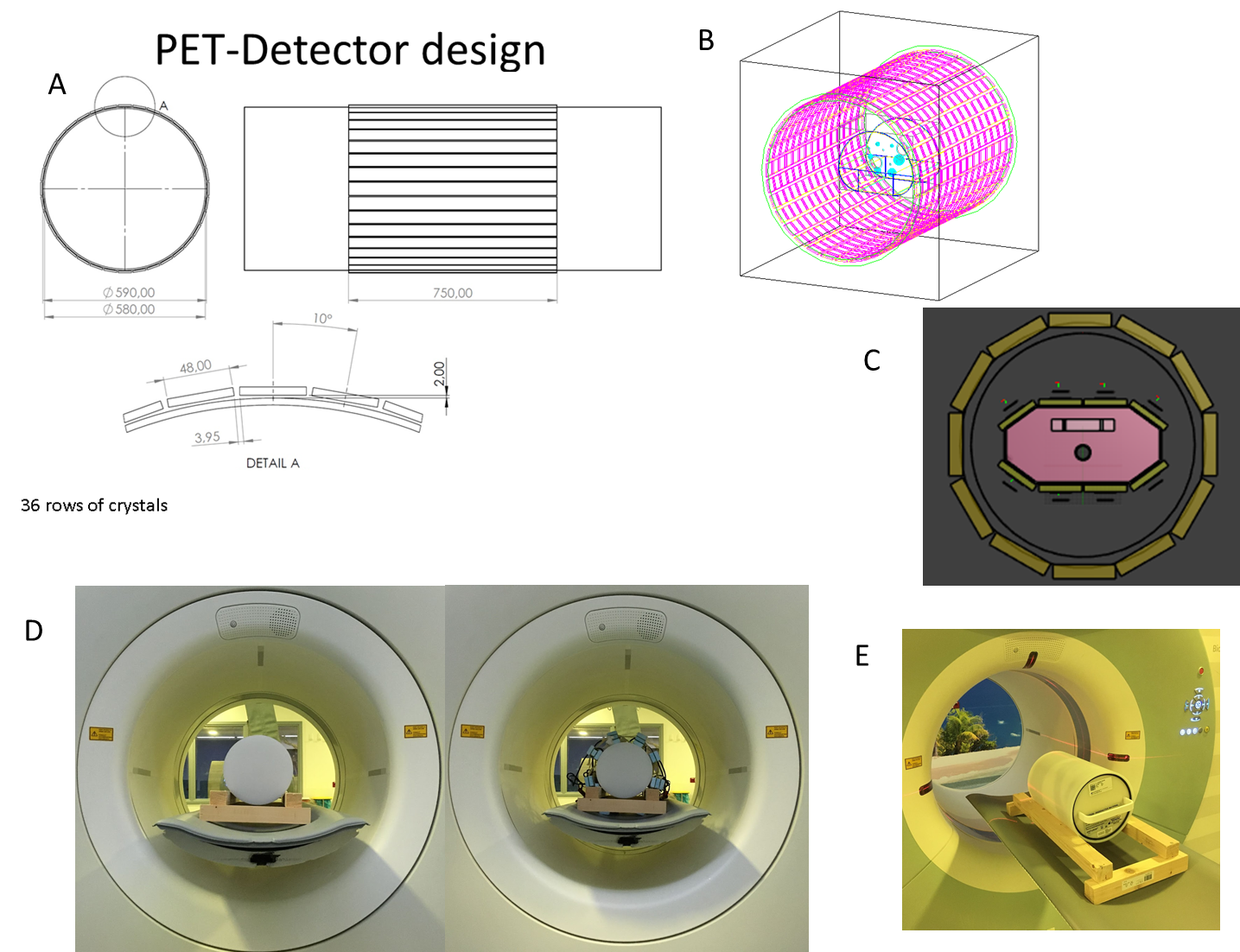
Figure 1:
A :The PET detector design with 36 rows of crystals
B: 3D model of PET setup
C: EM simulation model showing PET detector ring, RF shield, RF 1H/31P stacked array and phantom - moving inwards
D: The PET scan setup consists of the phantom alone, (left) and the phantom with the 1H/31P stacked element arrays arranged radially with the cables routed along the z-axis (right).
E: PET phantom positioning
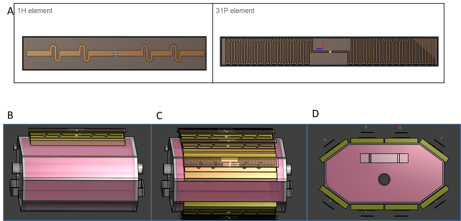
Figure 2:
A: PCB schematic of 1H element (left) and 31P element (right)
B: single set of stacked 1H/31P elements on phantom
C: Full EM simulation setup of eight sets of 1H/31P stacked elements on phantom - side view
D: Full EM simulation setup of eight sets of 1H/31P stacked elements on phantom - front view
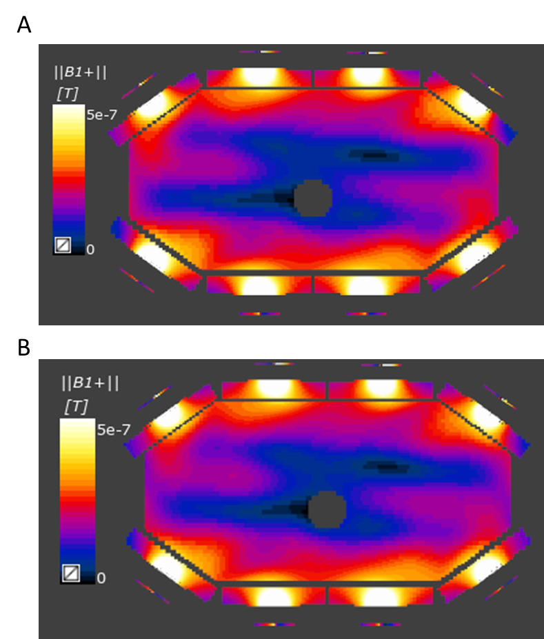
Figure 3: 1H simulation results of B1+ in phantom show insignficant differences
A: In the presence of RF shield of 29.5cm radius
B: In the absence of RF shield
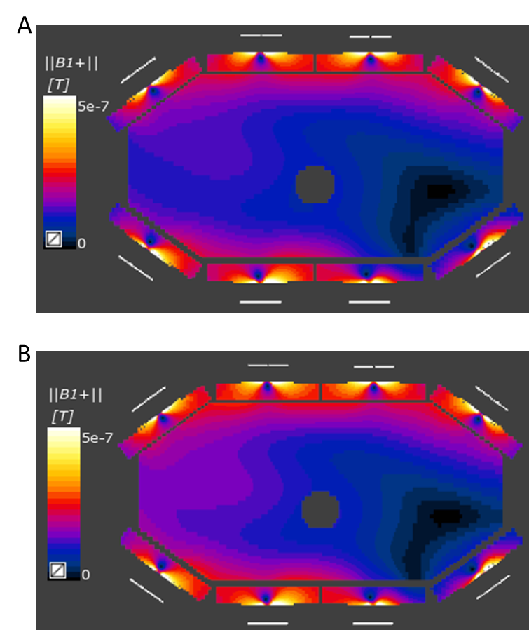
Figure 4: 31P simulation results of B1+ in phantom show insignficant differences
A: In the presence of RF shield of 29.5cm radius
B: In the absence of RF shield
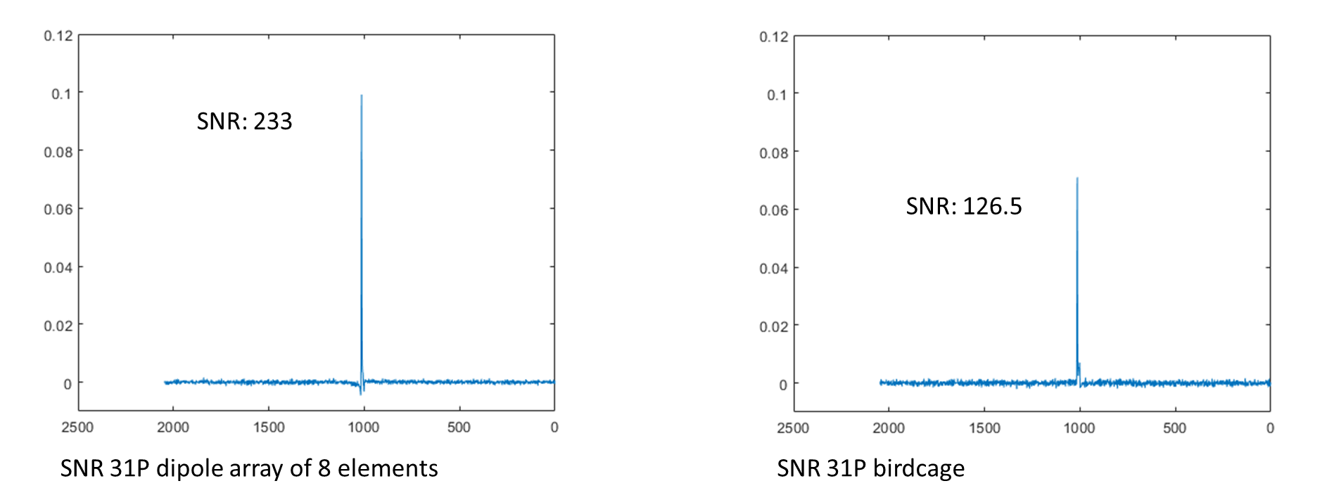
Figure 5:
SNR comparison of shimmed 8-channel array (left, SNR of 233) and 31P birdcage (right, SNR of 126) shows that the B1 shimmed array outperforms the birdcage with fixed 0/90 degree phase settings