1287
The HYPMED PET/MRI Insert for Breast Cancer1Physics of Molecular Imaging Systems (PMI), Experimental Molecular Imaging (ExMI), Aachen, Germany, 2Hyperion Hybrid Imaging Systems GmbH, Aachen, Germany, 3Futura Composites B.V., Heerhugowaard, Netherlands, 4NORAS MRI Products GmbH, Hoechberg, Germany, 5Philips Research, Eindhoven, Netherlands, 6Delft University of Technology, Delft, Netherlands, 7Forschungszentrum Juelich, Juelich, Germany, 8Department of Diagnostic and Interventional Radiology, University Hospital Aachen, Aachen, Germany, 9Physics Institute III B, RWTH Aachen University, Aachen, Germany, 10Fraunhofer Institute for Digital Medicine MEVIS, Aachen, Germany
Synopsis
Within the H2020 EU project HYPMED, we have developed a PET insert that can be moved into a 1.5 T MRI Philips Ingenia turning this into a simultaneous MRI-PET device for breast cancer applications. The PET insert consists of two independent PET rings with a field of view of 28$$$\times$$$10 cm² and two dual-channel local receive coils. Each ring consists of 14$$$\times$$$2 detector blocks of which each features a three-layer LYSO crystal array with 1.3 mm pitch. We will present the first PET and MRI results of our system.
INTRODUCTION
Improving the spatial resolution and system sensitivity of PET systems has always been a driver for innovation. Total-body PET/CT systems have been recently introduced that increase sensitivity by at least a factor of four for a single organ [1]. However, they are unfortunately subject to the same physical limitations with respect to the spatial resolution of about 3 to 4 mm [2]. The EU H2020 project HYPMED will address the above needs by developing a PET insert for a clinical 1.5 T MRI for breast cancer imaging.METHODS
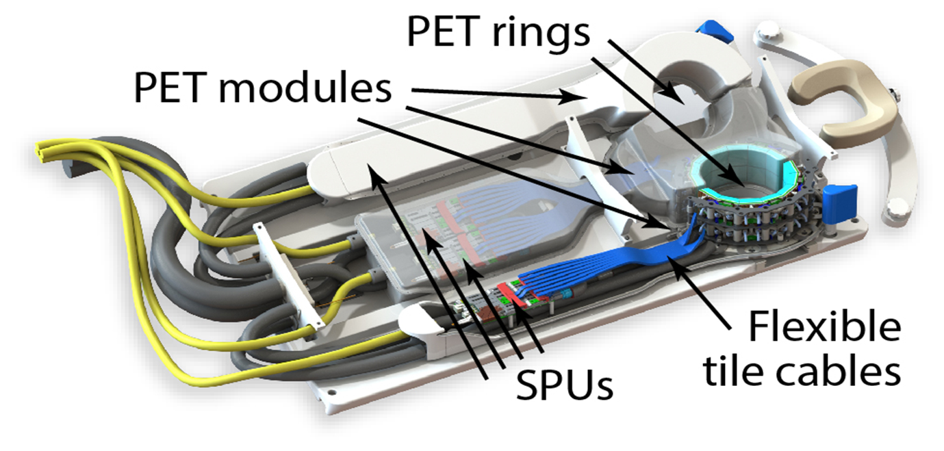
The HYPMED insert consists of a combination of two local 2-channel receiver coils and two local PET rings that allow simultaneous imaging of the female breast in the prone position at 1.5 Tesla. The two local PET detector rings are arranged at an out-of-plane angle of $$$\pm$$$ 20° to better follow the thoracic contour. Each ring can be opened and closed (Fig. 1). 2$$$\times$$$14 detector stacks form one ring leading to a field of view of approximately 10 cm. The detector stacks consist of three-layer LYSO crystal arrays with a pitch of 1.3 mm. In this way, the insert is developed to achieve high and homogeneous resolution across the fields of view. The MR-compatible detector is based on the Hyperion III platform [3] (Hyperion hybrid imaging systems GmbH, Aachen, Germany). The platform offers a sensor tile with 12$$$\times$$$12 individual digital SiPM channels (DPC-3200, Philips, the Netherlands) forming a sensitive area of ~ 48$$$\times$$$48 mm² each.RESULTS
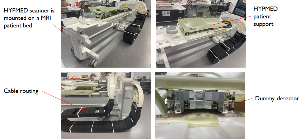
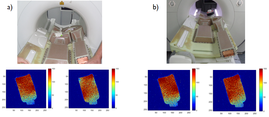
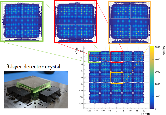
All system components are completed (Fig. 1 and 2), and individual investigations will be presented. SNR investigations of the local receive coils show good SNR for biopsy and diagnostics mode (Fig. 3). MR-compatibility studies of the developed Hyperion III detector platform are presented using previously developed protocols [4]. Flood maps of one three-layer detector stack were measured and show excellent ability to identify most of the 3,425 crystals (Fig. 4). The PET electronics have been successfully tested for gradient interference and show B0 interference for the detector stacks < 1 ppm in FOV. At the highest slew rates and duty cycles of the MRI system, a slight temperature effect on the detector stacks was observed, but no data rate loss was noticed (Fig. 5).DISCUSSION
The results demonstrate the feasibility of a dedicated PET insert that can be added as an add-on to an MRI. The use of the B1-Tx concept can be easily seen by the SNR plots of the right receiving coil, which supports both PET configurations (PET ring open and closed). Gradient switching shows no direct effect on the energy and timing resolution of the Hyperion III platform. With ~ 300 ps (FWHM) coincidence timing resolution with clinical detector stacks, the platform shows excellent PET performance in simultaneous operation. More details on the system will be shown during the conference.CONCLUSION
Local PET detectors in combination with a stand-alone clinical 1.5 T MRI system are a promising approach for high-resolution PET/MRI imaging of single organs, e.g., the female breast. With its higher sensitivity and improved spatial resolution, it offers an attractive alternative to commercially integrated PET-MRI.Acknowledgements
This project has received funding from the European Union’s Horizon 2020 research and innovation program under grant agreement No 667211.References
[1] Cherry, S.R., Jones, T., Karp, J.S., Qi, J., Moses, W.W. and Badawi, R.D., 2018. Total-body PET: maximizing sensitivity to create new opportunities for clinical research and patient care. Journal of Nuclear Medicine, 59(1), pp.3-12.
[2] Reddin, J.S., Scheuermann, J.S., Bharkhada, D., Smith, A.M., Casey, M.E., Conti, M. and Karp, J.S., 2018, November. Performance evaluation of the SiPM-based Siemens Biograph Vision PET/CT system. In 2018 IEEE Nuclear Science Symposium and Medical Imaging Conference Proceedings (NSS/MIC) (pp. 1-5).
[3] Weissler, B., Gebhardt, P., Dueppenbecker, P.M., Wehner, J., Schug, D., Lerche, C.W., Goldschmidt, B., Salomon, A., Verel, I., Heijman, E. and Perkuhn, M., 2015. A digital preclinical PET/MRI insert and initial results. IEEE transactions on medical imaging, 34(11), pp.2258-2270.
[4] Wehner, J., Weissler, B., Dueppenbecker, P.M., Gebhardt, P., Goldschmidt, B., Schug, D., Kiessling, F. and Schulz, V., 2015. MR-compatibility assessment of the first preclinical PET-MRI insert equipped with digital silicon photomultipliers. Physics in Medicine & Biology, 60(6), p.2231.
Figures