1204
Characterising the Magnetic Field Inhomogeneity for Open MRI at 0.5T using a Screened Coil NMR Probe Design1Sir Peter Mansfield Imaging Centre, School of Physics and Astronomy, University of Nottingham, Nottingham, United Kingdom
Synopsis
Image distortion caused by field inhomogeneity and instability is a major limitation for open MRI systems. Magnetic Field Monitoring (MFM) is a well-documented approach to characterise and thus compensate for these effects using an array of NMR probes. Here a novel NMR probe with a secondary coil is presented, which is designed to protect the pre-amplifier during transmission of a uniform B1 field. Preliminary data has verified this result and temporal variations of the B0 field have been observed. This approach will be developed with multiple probes to measure and compensate for the spatio-temporal response of the system.
Introduction
Open MRI has huge potential advantages over conventional MRI, as a tool for experimental medicine and in clinical MRI, but instabilities in magnetic fields can limit the performance of open MRI systems. The static field is more prone to inhomogeneity and instability compared to a cylindrical magnet because of eddy currents in the poles which can produce spatio-temporal field variations. The bi-planar gradient coils are sub-optimal compared to cylindrical gradient coils in terms of efficiency, switching rate and linearity. The resulting spatio-temporal field variations can cause image distortion, blurring and signal loss1,2. Modern approaches allow for these field imperfections to be included in the reconstruction3, but to do this the exact form of the fields needs to be known.Magnetic Field Monitoring (MFM) is a well-documented approach to characterise and thus compensate for these effects in MRI systems4, using an array of nuclear magnetic resonance (NMR) probes (a field camera). Typically, these probes5,6 use a single inductor tightly wound around the sample to maximise the filling factor and increase the NMR signal from the sample.
We aimed to design, manufacture, and test a novel NMR probe for characterising and compensating the spatio-temporal response of the magnetic fields present within an open MRI system, to ultimately allow us to include exact field patterns in future image reconstruction. The probe was designed to be used as a receive coil within the RF field from the transmit coil built into the poles of the magnet.
Methods
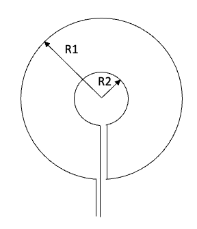
All work was performed on a 0.5T ASG Open MRI system.We have developed a novel NMR probe consisting of a secondary screened coil wound in series with the primary inductor but positioned such that when a uniform B1 field is applied externally from the transmit coil, the EMF induced in the screened coil cancels that produced in the inner coil (Figure 1). This protects the pre-amp during transmit without adding significant noise, allowing the (near full) B1 field to be applied to the sample of hydrated copper sulphate solution. For the system being investigated this is particularly important as there is no coil detuning gate signal available. In receive mode, the cancellation loop does not cancel the signal from the sample because of its relatively poor filling factor.
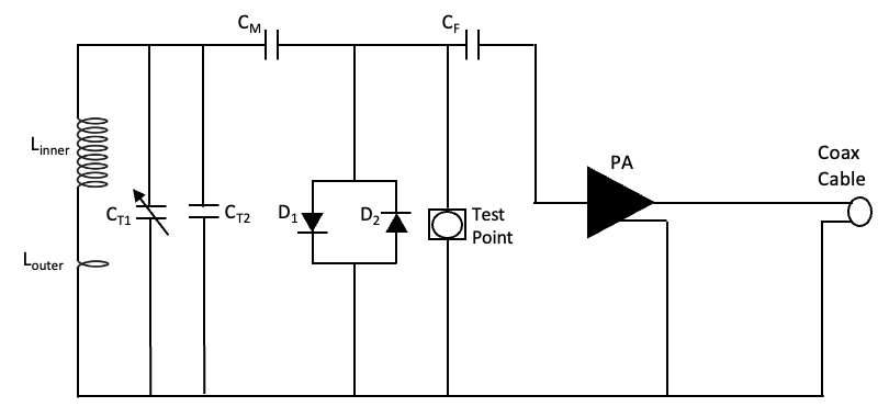
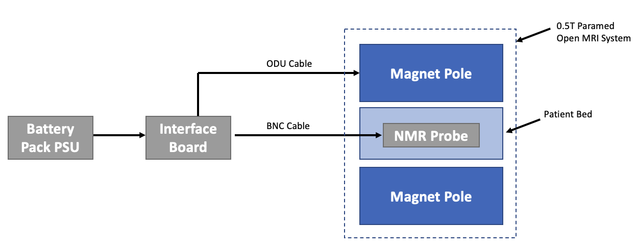
The NMR probe coil and pre-amp circuit (Figure 2) was manufactured using components with low noise figures in the relevant frequency range, and then optimised using a network analyser to achieve a 50-ohm input impedance, tuned to 21.15MHz and outer coil geometry was optimised to maximise cancellation. An interface board has been created to integrate the NMR probe with the open MRI system for test and characterisation (Figure 3).
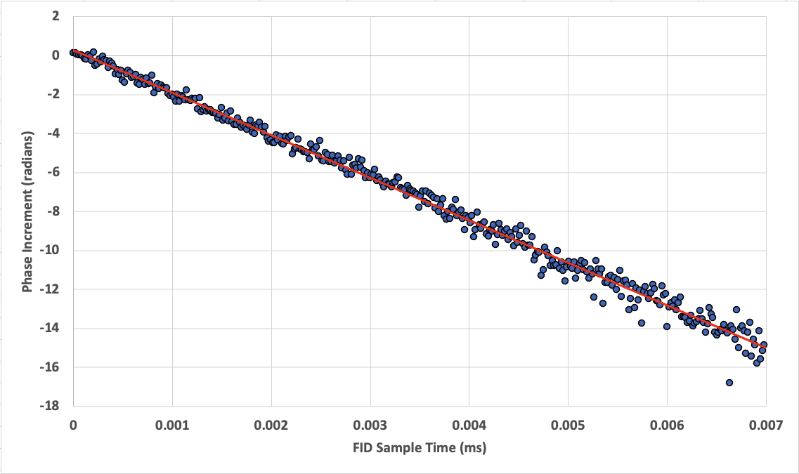
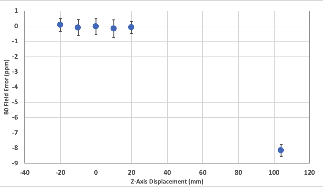
Preliminary measurements were made using a single NMR probe and a 1D pulse acquire sequence to measure the B0 field error (in Hz) over time. The field offset was calculated by summing the complex phase increment accrued during each FID for all time steps in Figure 4. A 1D field map was created by acquiring multiple FIDs at different bed positions in the z-direction (horizontal axis parallel to the face of both poles and equidistant between the poles) using a single NMR probe.
Results
The screened coil worked as expected, protecting the pre-amp, and not introducing additional noise.Figure 4 shows the field is stable over the period of acquisition of the FID. The 1D field map in Figure 5 shows that the B0 field is uniform around the isocentre (+/-20mm) but drops off at 104mm from the isocentre.
Discussion
A screened pick-up coil and sample has been designed to be used as a field camera at low field. The screening will allow less 'dead-time after RF excitation, so phase measurements can be acquired rapidly following an RF pulse.The initial field measurements are in line with previous measurements made by the system manufacturer. We will now fabricate multiple NMR probes, allowing us to sample the magnetic field variation over a sensitive volume about the isocentre. Appropriate placement of the field probes, coupled with knowledge of the underlying electromagnetic interactions will enable the calculation of the spatiotemporal field response for arbitrary gradient waveforms.
In the future, these measurements will be integrated with a commercially available optical motion tracking system to monitor patient position and correct for motion during retrospective reconstruction. Complete information on fields and position in fields will allow us to improve image quality for this open MRI scanner, thereby optimising its performance as a tool for future clinical applications.
Conclusion
We have developed an MFM system tuned to 0.5T for an open MRI system, using a screened coil.Acknowledgements
This research was supported by the EPSRC Grant EP/V025856/1References
[1] Marques, J. P. et al. J. Magn. Reson. Imag. 49, 1528–42, 2019.
[2] Wald, L. L. J. Magn. Reson. 306, 139–144, 2019.
[3] Norris, D. G. et al. Magn. Reson. Imaging 8, 33–37, 1990.
[4] Dietrich, B. E. et al. Magn. Reson. Med. 75, 1831–1840, 2016.
[5] Bammer, R. et al. Magn. Reson. Med. 57, 90–102, 2007.
[6] Janke, A. et al. Magn. Reson. Med. 52, 115–122, 2004.
Figures