1203
Development of a Low-Cost B0 Field Mapping Device1Research Campus STIMULATE, Otto von Guericke University, Magdeburg, Germany, 2Institute for Medical Engineering, Otto von Guericke University, Magdeburg, Germany, 3Department for Biomedical Magnetic Resonance, Otto von Guericke University, Magdeburg, Germany
Synopsis
Field mapping devices are used to determine the spatial distribution of magnetic fields. As magnetic devices are very unique in shape and size, commercially available mapping devices are often complex and customised and therefore too costly for small-format magnetic resonance imaging (MRI) systems and the open-source community. A low-cost field mapping device with a Hall sensor for the OCRA tabletop MRI system1 is developed. Field maps are measured and compared against a commercial Hall probe. The presented measurements show that the developed device can compete with commercially available devices.
Introduction
The analysis of magnetic field distribution is used to compare the magnetic field in an MRI system to the predicted simulated field. In low-field MRI systems, the static magnetic field (B0) is often generated by permanent magnets. Image quality is highly dependent on a homogeneous B0 field especially within the diameter of spherical volume (DSV). Field mapping devices are commonly used to evaluate the distribution of the magnetic field and the performance of the magnets. Commercially available devices are expensive (about $4.900 - $116.000, depending on the size) and are often not suitable for small-scale magnets with narrow gap distances2-5. In this study, a low-cost field mapping device with a commercial Hall chip IC (in the following abbreviated with HS) for small-scale MRI systems is presented and evaluated in comparison to a commercial Hall probe.Methods
The field mapping device contains a frame for scanning the magnet’s XY plane, where the position of the sensor is controlled by two stepper motors (see Figure 1). To avoid field disturbance by the mapping device, all mechanical components have to be non-ferromagnetic. 3D printed parts are a low-cost solution and are chosen where feasible. The IC chip AD22151 (Analog Devices) is implemented onto the printed circuit board (PCB) (see Figure 2). Here this linear HS is set for a measuring range of 0 to 290 mT and a sensitivity of 0.33 mT per step width. For a calibration of the HS, the OCRA tabletop MRI system1 is used. With the measured Larmor frequency of a water sample, the magnetic flux density is determined.The magnets of the tabletop system are N45 neodymium (NdFeB) with an expected magnetic field of about 0.26 T and are taken for the evaluation of the HS. The THM1176 magnetometer (Metrolab Technology SA5) is used as a commercially available reference, which is mounted onto the tip of the rack of the field mapping device. The measurement of the magnetic flux density (Bz) is sampled with a step of 5 mm in the X and Y directions in the central plane. At each sample point, the average of 1000 measured values is computed. For the calculation of the deviations, a circular area with a diameter of 40 mm around the isocentre was considered. The reproducibility of motor positioning is tested by moving 10 times to the same position and measuring the deviation with a dial gauge. The user can control the field mapping device via the GUI and analyse or export the data.
Results
The comparison between Metrolab and the HS shows a deviation of the magnetic flux density of 0.9 % to each other within the 40 mm area (see Figure 3). An accuracy of ± 1 % (gain error) and ± 0.6 mT (offset error) can be achieved with the HS. Two peaks with around 2.6 % higher value than within the DSV area can be found in the line plot (see Figure 4). For the reproducibility of motor positioning, a deviation of 0.1 mm for a travel distance of 160 mm is detected. The material costs for the field mapping device are about $300.Discussion
Within the homogeneous range, the comparison shows good agreement with the commercial Hall probe (resolution: 0.1 mT, accuracy ± 1 %). Remaining deviations and measurement errors can result from temperature drifts and different sizes of the sensitive areas of the sensors, which in the case of the HS is about twice as large as that of the Metrolab. Differences in the mounting of the holder of the Metrolab and the HS onto the rack of the field mapping device can lead to a position offset of < 1 mm due to the long shaft of the rack and sensor holder. The peaks are related to the geometry of the pole shoes, which are used for passive shimming. The data obtained from the measurement can be taken for the construction of magnets and for the selection of materials in the future in order to achieve a higher homogeneity in the DSV by calculating the spherical harmonics for active shimmingConclusion
The presented low-cost field mapping device with its HS is able to measure the magnetic field distribution as precise as a commercially available device. Except for the motors, all components are made of non-ferromagnetic materials to reduce the influence on the measurement data. With the field mapping device and the self-build HS, a wide measurement range within a large measurement volume of 470 x 420 x 240 mm can be detected. The analysis of the magnetic field distribution is especially possible for small-size magnet systems with a narrow gap distance like the tabletop MRI1. Nevertheless, for an exact measurement of the magnetic flux density within the homogeneous field, an NMR probe is useful, which can be easily attached to the shaft of the device. With the microcontroller, it is possible to implement a third motorised axis to obtain a fully automatic 3D field map.Acknowledgements
The work of this paper is partly funded by the Federal Ministry of Education and Research within the Research Campus STIMULATE under the number '13GW0473A' and by the International Graduate School MEMoRIAL at Otto von Guericke University (OVGU) Magdeburg, Germany, kindly supported by the European Structural and Investment Funds (ESF) under the programme "Sachsen-Anhalt WISSENSCHAFT Internationalisierung“ (project no. ZS/2016/08/80646).References
1. M. Prier et al. “Educational Tabletop MRI system using the Open-Source Console for Real-time Acquisition (OCRA)” In: ISMRM 29th annual Meeting, 2021.
2. SENIS AG. “Magnetic field mapper system MMS-1X-RS”. URL: https://www.senis.swiss/mappers/large-size-all-in-one-magnetic-field-mapping-system-mms-1x-rs. Accessed on: Oct 22, 2021.
3. Hunan Linkjoin Technology Co., Ltd. “Magnetic field mapper system MATS-2100RMT”. URL: http://www.linkjoin.com/English/Sys/Products/Site_PageTplSee.asp?PkValue={364D371D-02E9-41D7-B6DC-49DBEB7A1744}&nPkValue={A85C132B-8339-4781-A3E8-DAF0156618EB}&MenuName=Model%20MATS-2100RMT#See. Accessed on: Oct 22, 2021.
4. Magcam NV “Magnetic field mapper system Magcam Portal Scanner”. URL: https://www.magcam.com/product/magcam_magnetic_field_scanner. Accessed on: Oct 22, 2021.
5. Metrolab Technology SA “THM1176-MF-B1 3-axis Hall Magnetometer”. URL: https://www.metrolab.com/products/thm1176-three-axis-hall-magnetometer/. Accessed on: Oct 22, 2021.
Figures
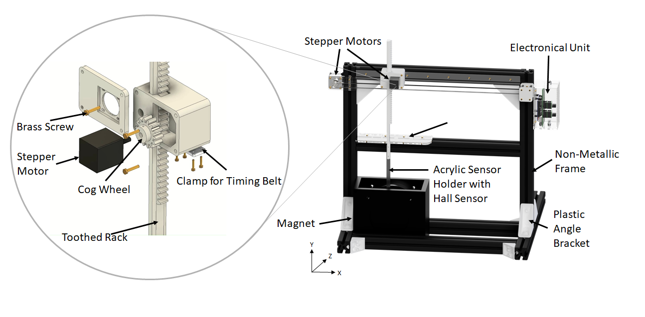
Figure 1: Field mapping device with a linear HS IC mounted on a PCB in order to measure total magnet volume. A 2D Measurement runs fully automatically using two stepper motors for movements in the XY plane. The guiding rail provides a second support point to align the toothed rack parallel to the magnet's wall. Non-metallic materials were installed, except for the motors and Arduino, which were placed at a sufficient distance from the magnet to avoid field disturbance with the measurement.
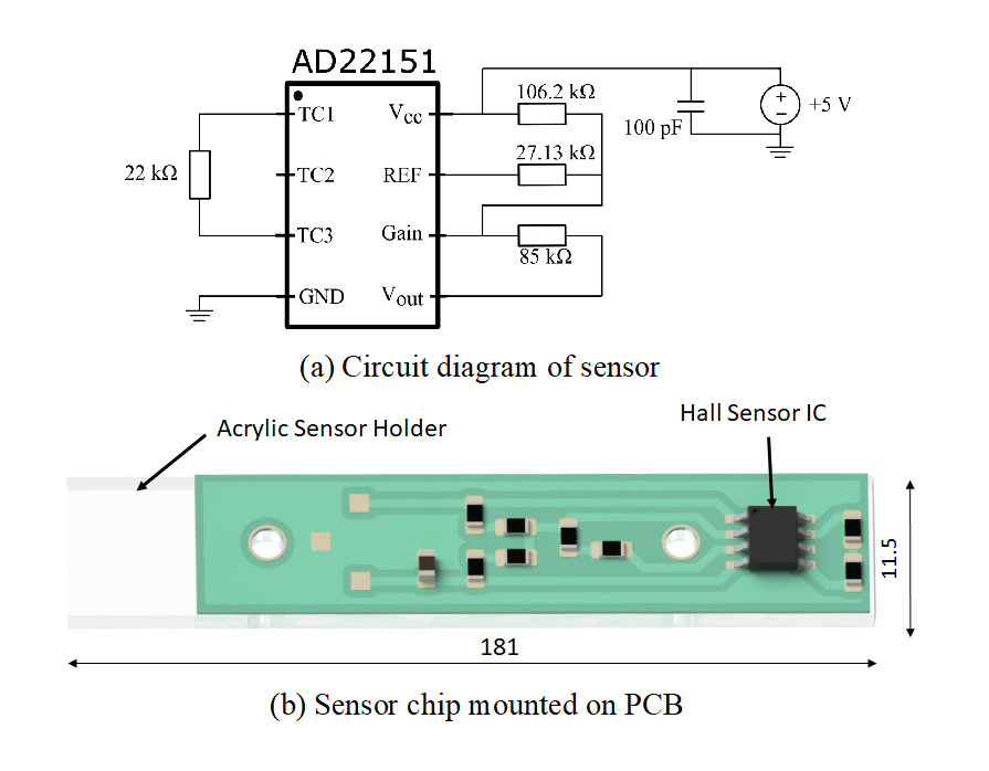
Figure 2: The offset and gain of the HS IC can be adjusted via external resistors. This shown setup allows a measuring range of 0 to 290 mT. The IC is suitable for a field strength up to 500 mT (a). The PCB with the HS IC is mounted on an acrylic sensor holder with a dimension of 181 x 11.5 x 5.3 mm, which allows to evaluate large volumes. The small outline makes it suitable for small-scale MRI systems (b).
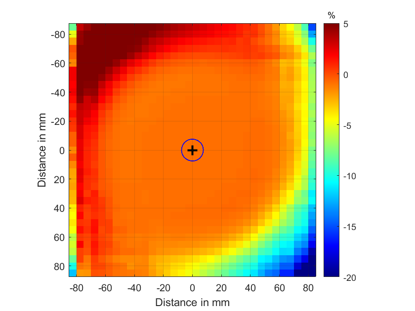
Figure 3: Percentage difference between Metrolab and HS, Ø 15 mm (Field of View): 0.91 %, Ø 40 mm: 0.91 %, Ø 100 mm: 0.91 %, Ø 140 mm: 0.90 %, Ø 165 mm: 1.15 %.
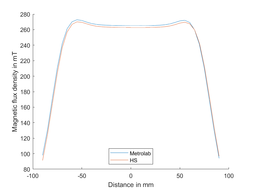
Figure 4: Comparison between a commercially available magnetometer with the HS in the central plane (vertical slice, x=0). Manual replacement of the sensor holders of the first prototype leads to small positioning offsets.