1202
A new single channel method for electromagnetic interference reduction on a 50 mT permanent magnet system1Percuros B.V., Leiden, Netherlands, 2Leiden University Medical Center, Leiden, Netherlands
Synopsis
External electromagnetic interference (EMI) in unshielded low field and portable MRI systems can swamp the signal, and various multi-detector methods have been developed to minimize it. A new EMI cancellation method designed for a single-channel receiver-system has been implemented on a 50 mT system by using the MR-inactive channel of a birdcage coil and a 180o power hybrid. This method results in up to a 97% reduction in the standard deviation of external EMI.
Introduction
Low field MRI has received much attention in recent years due to its low cost and portability 1-3, along with the possibility of its use outside of RF shielded environments in unconventional locations. However, this increases the potential for substantial electromagnetic interference (EMI) created by equipment close to the scanner, in the image. Many different methods to reduce EMI for MRI/NMR have been explored in the past4-10, mostly by using external sensors, with impressive results shown recently for a multi-channel low field system10. In this work, we test a simple single-channel approach on a Halbach-based low field MRI system operating at 2.15 MHz1, using a birdcage coil with the MR-inactive port detecting only the EMI. Phantom and in vivo images with and without EMI have been acquired to evaluate the approach.Methods
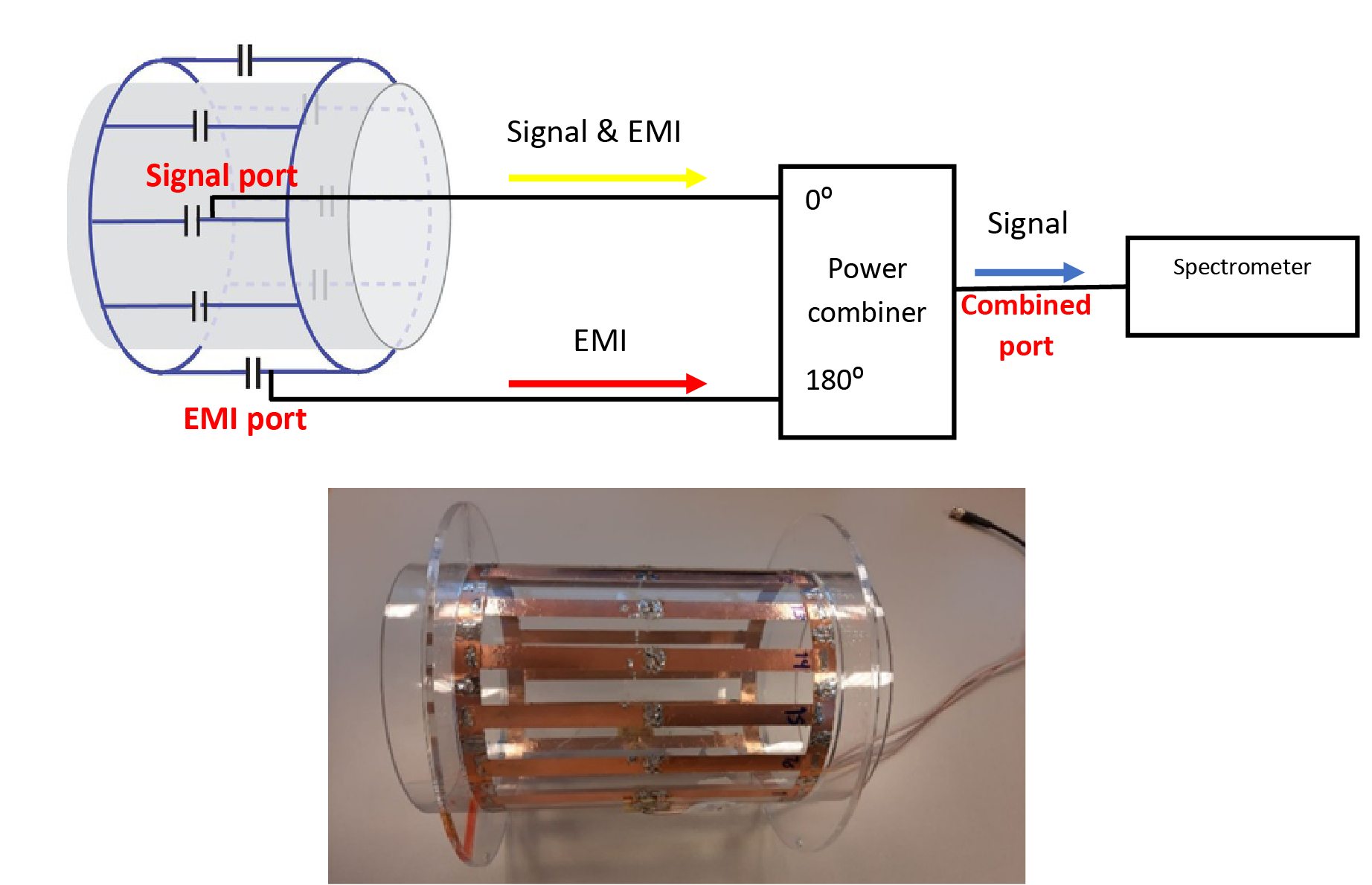
The concept of the EMI-cancellation scheme is shown in figure 1. One channel of a circularly-polarized birdcage coil with the B1-field orthogonal to the transverse B0-field acquires signal plus EMI, while the other channel with the B1-field parallel to B0 only detects the EMI. For a simple acquisition system which only has one receive channel, the signals are subtracted using a 180o power combiner which makes the overall cost and complexity of the total system as low as possible.A 16-leg low-pass transmit/receive birdcage for knee and calf muscle imaging was designed, simulated, and constructed (Figure 1). The coil dimensions were 19 cm × 16 cm × 16 cm to accommodate the human knee. The birdcage coil was constructed on a plexiglass cylinder using copper tape with 13 mm width and 0.06 mm thickness (Figure 1). A 180⁰ power splitter/combiner (SBTCJ-1W+, Mini-Circuits, NY, USA), placed inside an aluminum shielded box, was connected to the two ports.
To test the method three different imaging setups were considered. First, the normal operating mode in which the subject’s torso is covered by a conductive blanket (Holland Shielding Systems, Dordrecht, the Netherlands) and all other sides of the Faraday cage are closed. Second, an unshielded state (no blanket, Faraday cage open) with a 2.15 MHz sine wave produced by a function generator (33500 Series waveform generators, Agilent Technologist, US) acting as a narrow band EMI. Finally, unshielded as for the previous case, with a broadband EMI broadcast over a frequency range 0-3 MHz. For each of these setups, the following data were acquired. First, with only the MRI signal (S) port connected directly to the spectrometer, second with only the EMI port connected, and third the full setup with both the S and EMI ports connected via the power combiner to the spectrometer (Figure 1). A 3D turbo spin-echo (TSE) sequence was used to obtain images. The sequence parameters for the phantom (water-containing cylinder with diameter 14 cm, length 90 cm) imaging were TR/TE: 1000 ms/15 ms, FOV: 150x150x300 mm, 2x2x5 mm resolution, and one average. In-vivo TSE parameters were TR/TE: 250 ms/15 ms, FOV: 160x160x200 mm, 2x2x5 mm resolution, two averages, and two volunteers.
Results
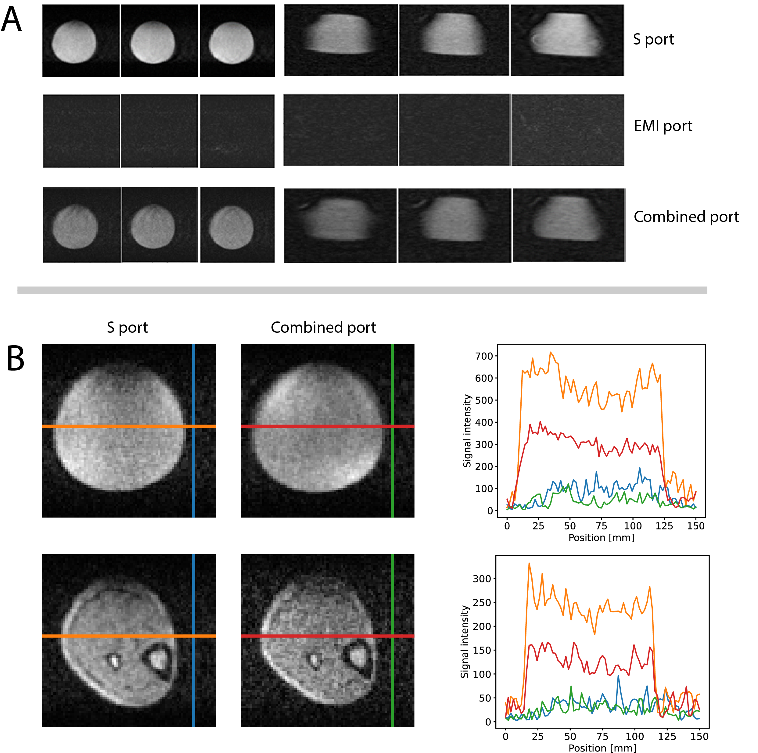
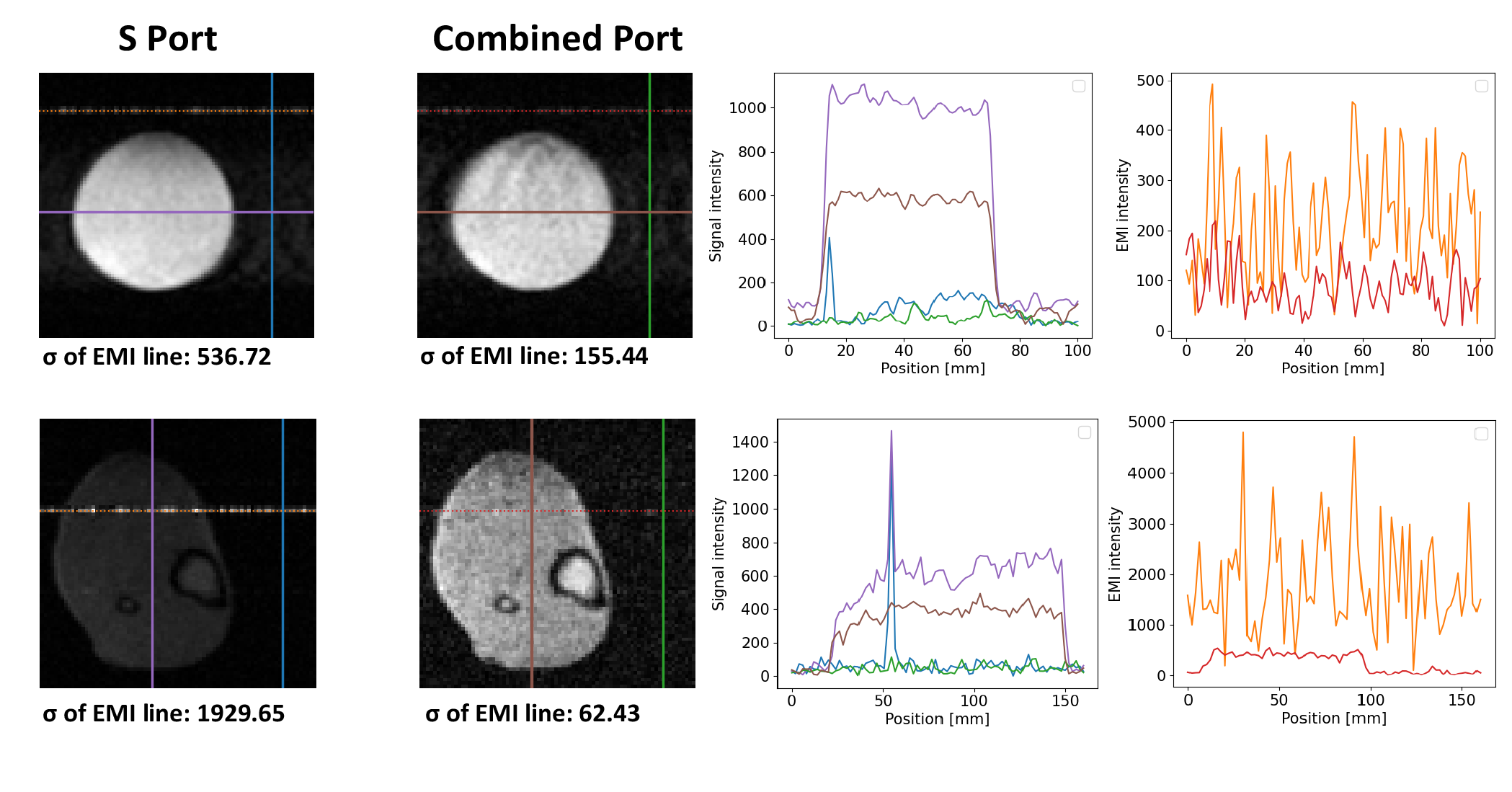
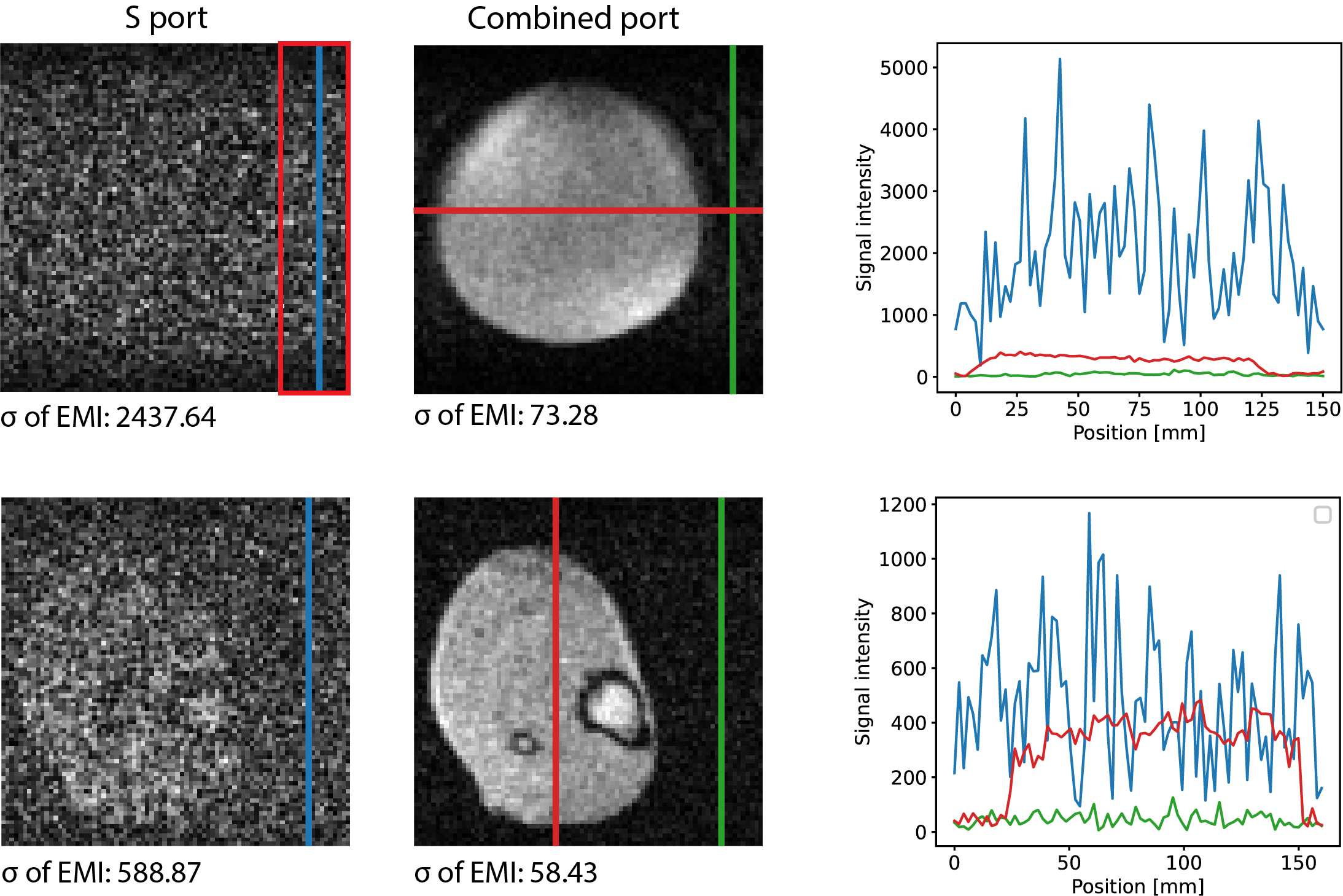
Reflection coefficients (S11) for each port and coupling between two ports (S12) were lower than -27 dB. Power splitter evaluation gave less than 0.2 dB insertion loss, 0.5⁰ phase unbalance, and -25 dB inter-channel isolation. Figure 2 shows results acquired from the first shielded setup. The ratio of the signal from the S port to that of the EMI port was 45:1, representing a greater than 97% isolation between the ports. The signal from the combined port was reduced by ~40% compared to that of the S-port without the combiner present due to the inherent 3 dB reduction in signal and noise from the 180o hybrid. In the second experiment (figure 3), the standard deviation of the single line of narrowband EMI throughout the image was measured and resulted in 97% and 71% reduction for the phantom and in vivo images, respectively. Figure 4 shows the third setup in which broadband EMI cancellation was 97% for the phantom and 90% for the in vivo images, respectively.Discussion and Conclusion
A new EMI cancellation method has been introduced and tested for a 50 mT Halbach-based portable MRI system under different EMI conditions. A significant reduction in EMI was achieved using the new design. This simple approach has both advantages and limitations with respect to other methods. It does not require external sensors or extensive signal processing and can be implemented on a single receiver console. However, the use of a 180o power combiner does reduce the signal by 40%. The approach also relies on the external interference having essentially random polarization. Finally, the birdcage coil used here does have lower sensitivity than an equivalently-sized solenoid, although the solenoid also picks up a much larger EMI signal than the birdcage due to its B1 spatial distribution which extends out of the magnet.Acknowledgements
This work was funded by H2020-MSCA-ITN-ETN-2019 (NOVA-MRI 859908) and a Horizon 2020 ERC Advanced Grant (670629), Horizon 2020 ERC Advanced NOMA-MRI 670629.References
1. O’Reilly T, Teeuwisse W M, and Webb A G, In vivo 3D brain and extremity MRI at 50 mT using a permanent magnet Halbach array. Magn Reson Med. 2020;00:1-11.
2. Hyperfine - Portable MR Imaging: Bringing MRI to the Patient. https://hyperfine.io/?gclid=Cj0KCQiAx9mABhD0ARIsAEfpavS44Ax2KT5LfC36K 95GbfZRUMXzf jyhkn0uwexFSyjqf933fxu5qAaAszcEALw_wcB. Accessed Jan. 31, 2021.
3. Cooley C Z, et al. A portable scanner for magnetic resonance imaging of the brain. Nature Biomedical Engineering. 2021; 5:229–239.
4. T Brosnan, F. Graham Sommer, Noise reduction in magnetic resonance imaging, Magn Reson Med. 1988; 08:394-409.
5. S. Vaishali, K. K. Rao, and G. V. S. Rao, "A review on noise reduction methods for brain MRI images," 2015 International Conference on Signal Processing and Communication Engineering Systems; 2015: 363-365.
6. M. K. Laudon, J. G. Webster, R. Frayne, and T. M. Grist, "Minimizing interference from magnetic resonance imagers during electrocardiography," in IEEE Transactions on Biomedical Engineering, 1998; 45: 160-164.
7. D.V. Trushkin, O.A. Shushakov, A.V. Legchenko. The potential of a noise-reducing surface NMR groundwater surveys in the earth’s magnetic field Geophys. Prospect. 1994: 855-862.
8. E. Dalgaard, E. Auken, J.J. Larsen Adaptive noise canceling of multichannel magnetic resonance sounding signals. Geophys. 2012; 19: 88-100
9. T. Kremer, J.J. Larsen, F. Nguyen Processing harmonic EM noise with multiple or unstable frequency content in surface NMR surveys Geophys. J. Int. 2019; 119: 753-775.
10. Sai Abitha Srinivas, and et al. External Dynamic InTerference Estimation and Removal (EDITER) for low field MRI. Magnetic Resonance in Medicine 2021, https://doi.org/10.1002/mrm.2899
Figures