1200
Simulating the effects of off-resonance effects from a CHORUS pulse sequence in a single sided, low-field MRI system.1Yale School of Engineering & Applied Science, Yale, New Haven, CT, United States, 2Promaxo, Oakland, CA, United States, 3Biomedical Engineering, Vanderbilt University, Nashville, TN, United States
Synopsis
Moving towards single-sided, low-field MRI systems can increase the portability and access to this invaluable clinical tool. However, the B0-fields generated by these systems are highly inhomogeneous, and severe artifacts arise when the RF pulse does not cover the full bandwidth of spin resonances. In this study, we have developed a simulation algorithm that will allow us to better simulate the phase variations induced by B1 and B0 inhomogeneities and help us design RF schemes to remove unwanted phase to produce higher quality images.
Introduction
Low-field, portable MRI systems have the potential to significantly reduce the cost of and increase access to MRI devices. However, the magnetic fields produced by these systems are inhomogeneous, making it difficult to use conventional MRI techniques for imaging1. For example, the Promaxo scanner has a field that ranges from 58 to 74 mT across its imaging region, thus requiring RF pulses with wide bandwidths to excite spins. Frequency swept chirped pulses are a suitable solution, but tend to impart phase dispersals across the field of view2. Some of these dispersals come from the Bloch Siegert phase imparted on the sample by the off-resonance pulses. Previous studies have shown that the quadratic phase can be removed by setting the sweep rates of the pulses correctly however, Bloch-Siegert phase contributions cannot be removed with this method 3,4,5Therefore, imaging with a single sided scanner requires a better understanding of the B1 and B0 inhomogeneities, and how they contribute to the imaging artifacts. We have built a simulation algorithm that allows us to analyze the phase dispersals induced by chirp RF pulses, and aids in designing pulse sequences that minimize signal loss, thereby generating higher quality images.
Methods
A Bloch simulation was developed to study the effects of inhomogeneous B0 and B1-fields on the signal phase evolution during chirped ordered pulses for an ultrabroadband spectroscopy (CHORUS) pulse sequence. The simulation uses a 3x3 rotation matrix defined by the Cayley-Klein parameters to determine the action of the RF pulses on the magnetization of isochromats at various time points. The RF pulses were simulated using B1 maps measured over the entire FOV, and for a range of B0 off-resonance frequencies. A linear gradient was used to simulate the inhomogeneous B0.A CHORUS sequence was simulated to understand how the off-resonance phase affects the signal phase coherence 6,7. The first pulse is an excitation pulse, followed by two refocusing pulses with their amplitudes and durations set to remove the quadratic phase imparted by the excitation pulse. Figure 1 shows the pulse design for the first refocusing pulse. The pulse has a linear frequency sweep with a width of 40kHz, over a duration of 3.2ms. The amplitude of the pulse tapers off at the edges. The excitation and second refocusing pulses use the same pulse profiles and sweep widths, but with durations of 2.4ms and 2ms respectively.
Figure 2 shows an example of the CHORUS pulse sequence used on the Promaxo scanner. Removing the quadratic phase from the magnetization excited with chirped pulses is typically done by setting the sweep rate of the refocusing pulse to twice that of the excitation8. However, with CHORUS the durations of the two refocusing pulses are mismatched by half the duration of the excitation pulse, resulting in quadratic phase rewinding after the third RF pulse.
Results
Figure 3 shows the results from simulating the CHORUS pulse sequence over an 80kHz bandwidth. The Bloch simulations illustrate how after the first refocusing pulse, a spectral echo is created from different isochromats refocusing at different times depending on where they occur along the frequency sweep. By applying the second refocusing pulse with a shorter duration, the quadratic phase is removed, and the spectral echo is restored to a conventional echo.Figure 4A shows the phase maps generated from the Bloch simulation at the center of the conventional echo signal, for various off-resonance frequencies. Figure 4B is a plot of the phase profile in radians along a vertical line through the center of the FOV. While the phase is quite smooth in the imaging region (gray box), there are still nonuniformities induced by the inhomogeneous B1-field, and the B0 off-resonance frequencies. It may be possible to adjust for these phase differences by adjusting the amplitude or sweep pattern of the RF pulses. We are currently working on incorporating real B0 maps into the simulation so we can better study the effects of spatially varying B0-inhomogeneities on the signal phase.
Discussion
Significant phase variations in the field of view can be seen in Figure 4. These phase variations can lead to destructive interferences in the image. When spins are on-resonance, the phase is stable in the middle of the FOV, only changing at the edges. In general, the phase varies much more drastically when spins are off-resonance. With this information, in the future we will design pulse sequences that minimize these phase variations and evaluate their performance with experiments conducted on the Promaxo scanner.Conclusion
We have shown through simulation studies the extent of the phase variations imparted by off-resonance frequencies in a single-sided MRI system, thereby demonstrating the need to design pulse sequences that can minimize these variations to produce higher quality images.Acknowledgements
NoneReferences
1. Perlo, J., Casanova, F. & Blümich, B. 3D imaging with a single-sided sensor: An open tomograph. J. Magn. Reson. 166, 228–235 (2004).
2. Kupče, Ē. & Freeman, R. Adiabatic Pulses for Wideband Inversion and Broadband Decoupling. Journal of Magnetic Resonance, Series A vol. 115 273–276 (1995).
3. Cano, K. E., Smith, M. A. & Shaka, A. J. Adjustable, broadband, selective excitation with uniform phase. J. Magn. Reson. 155, 131–139 (2002).
4. Khaneja, N. Chirp excitation. J. Magn. Reson. 282, 32–36 (2017).
5. Lee, Y. et al. New phase-based B1 mapping method using two-dimensional spin-echo imaging with hyperbolic secant pulses. Magn. Reson. Med. 73, 170–181 (2015).
6. Power, J. E. et al. Increasing the quantitative bandwidth of NMR measurements. Chem. Commun. 52, 2916–2919 (2016).
7. Foroozandeh, M., Nilsson, M. & Morris, G. A. Improved ultra-broadband chirp excitation. J. Magn. Reson. 302, 28–33 (2019).
Figures
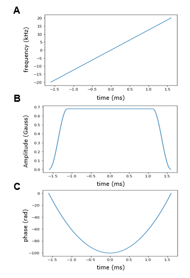
Figure 1. Design of the chirp refocusing pulse. A) The pulse was applied with a linear frequency sweep, a sweep width of 40kHz, and duration of 3.2ms.B) and C) show the amplitude envelope and phase of the pulse, respectively. The excitation pulse has the same profile but with a duration of 2.4ms and maximum pulse amplitude of 0.3
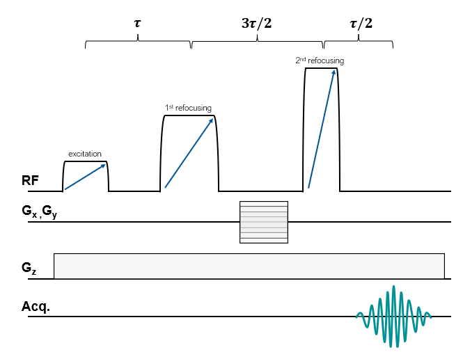
Figure 2. Pulse sequence design. Diagram of the CHORUS pulse sequence applied to the Promaxo scanner. The duration and amplitude of the of the first two refocusing pulse are mismatched, and the echo is collected after the second refocusing pulse to remove the phase imparted by off-resonance frequencies.
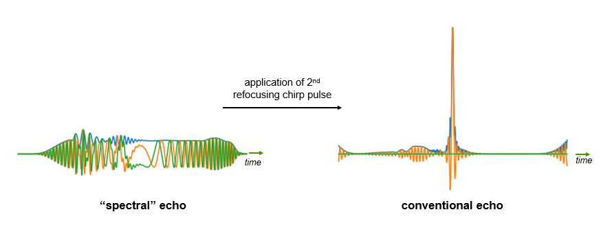
Figure 3. Simulated echo signal. A “spectral” echo is created after the first refocusing pulse (left) because of the different isochromats refocusing at different times. After the second refocusing pulse, the quadratic phase is removed created a more conventional echo. The sequence was simulated over an 80kHz bandwidth.
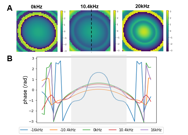
Figure 4. Phase maps. A) Phase map at center of the echo for three different off-resonance frequencies. B) Phase profiles over a vertical line through the middle of the FOV (black dotted line). The gray box indicates the imaging region.