1197
Measurement of magnetic fringe fields from a proton pencil beam scanning nozzle causing MR image ghosting artefacts during in-beam MR imaging1Institute of Radiooncology – OncoRay, Helmholtz-Zentrum Dresden – Rossendorf, Dresden, Germany, 2Centre for Medical Radiation Physics (CMRP), University of Wollongong, Wollongong, Australia
Synopsis
Proton therapy (PT) is expected to benefit from real-time MRI guidance. However, the integration of MRI and PT is challenging due to the interaction between the magnetic fringe fields of the PT beamline and the B0-field of the MR scanner. In this study, we measured the magnetic fringe field of the PT beamline. The measurement data will be used to validate a finite element model. With a match to this model, we can proceed to investigate what type of magnetic shielding solution would be needed to decouple the magnetic fields of the PT and MRI systems.
INTRODUCTION
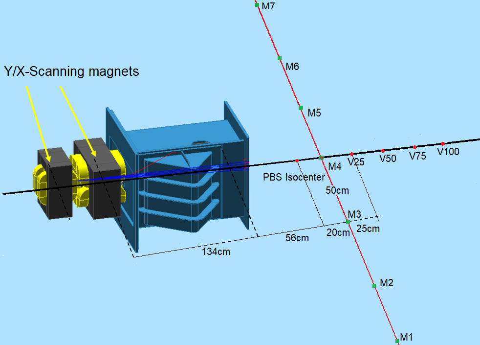
Proton therapy (PT) produces highly conformal dose distributions with steep gradients at the target boundaries due to the finite range of protons. This reduces normal-tissue doses, particularly at the distal side of the tumor where the Bragg peak is located. However, the targeting precision of PT is compromised by a lack of image guidance: imaging modalities in treatment rooms of PT facilities are often limited to X-ray based on-board 2D kV or 3D cone-beam CT imaging. The integration of fast real-time MR imaging could significantly improve on-board imaging and therefore increase the targeting accuracy of PT, especially for moving tumors1. However, a full integration of MRI and PT at the treatment isocenter is technically challenging due to the electromagnetic interaction between both systems. Although a first proof-of-concept for in-beam MRI has proven successful in combination with a static proton research beamline2, the combination of a research prototype in-beam MRI system with a beamline featuring an actively scanned proton beam (figure 1) has proven problematic. MR images acquired during proton pencil beam scanning (PBS) dose delivery were blurred by coherent ghosting artefacts due to dynamic magnetic fringe fields produced by nearby beam steering magnets overlapping with the B0 field of the MR scanner (figure 2)3. One way to eliminate these artifacts could be passive magnetic shielding of the beam steering magnets. This would lead to decoupling the magnetic fields of the MR scanner and the PBS nozzle. To be able to design an optimal shielding solution, a detailed understanding of the magnitude of the magnetic fringe fields produced by the PBS nozzle is mandatory. The aim of this study was to measure the magnetic fringe fields produced by the PBS nozzle. The experimental data will be used to help optimize and validate a finite element model (FEM) of the PBS nozzle that is under development.METHODS
A proton beam of therapeutic quality was generated by an isochronous cyclotron (C230, IBA SA, Louvain-la-Neuve, Belgium). The proton PBS nozzle of a horizontal research beamline included two sets of dipole magnets to scan the beam in horizontal (X) and vertical (Y) direction across a target volume during dose delivery. A fluxgate magnetometer (Mag649-200, Metrolab Technology SA, Geneva, Switzerland) was used to measure the magnitude of the magnetic fringe fields produced by the beam scanning magnets. It was positioned on a mobile tripod in front of the PBS nozzle at 13 locations as demonstrated in figure 3 at the height of the central beam axis (i.e. 126 cm above floor level). The delivery of two dose spot maps was emulated by energizing the magnets of the PBS beamline for a proton beam of 220 MeV, but no beam was released from the cyclotron in order to prevent radiation damage to the magnetometer. A beam energy of 220 MeV was chosen to achieve the maximum magnitude of magnetic fringe fields produced by the beamline magnets, and thus represent the worst-case scenario. Each dose spot map included a single dose point of 4500 monitor units (MUs) irradiated at a dose rate of approximately 155.2 MU/s. The X scanning magnets were energized to emulate the delivery of two dose spots to extreme positions at (X = -20 cm, Y = 0 cm) and (X = 20 cm, Y = 0 cm) relative to the beam isocenter. This experiment was repeated three times. The Y scanning magnets were not energized, as their fringe fields were previously shown not to affect the MR image quality3.RESULTS
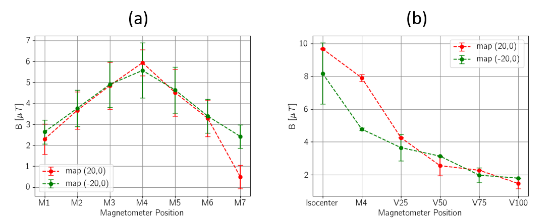
The maximum magnitude of the magnetic fringe field of scanning magnets was measured on the central beam axis at PBS isocenter (Figure 4). The fringe field magnitude varied from 2 µT to 6 µT over the volume where the in-beam MR scanner will be placed. A slight asymmetry in the measured values along the lateral direction (i.e. perpendicular to the central beam axis) was observed (see figure 4a).DISCUSSION
The resolution and the measuring range of the magnetometer are well suited to perform the measurements in the volume of high interest, i.e. the volume where the in-beam MR scanner is positioned. Even the 1 µT changes in the magnetic field, e.g., the asymmetry along the lateral direction, were detected. The asymmetric measurement results from the asymmetric design of the PBS nozzle. However, the resolution of 0.5 µT did not allow measurements in lower magnetic fields and the magnetometer became oversaturated in the regions of higher magnetic field strengths. Further measurements outside the volume in which the MR scanner is positioned, e.g., in the immediate proximity of the PBS nozzle where the magnetic field strength is largest, require a magnetometer with an extended measuring range and resolution.CONCLUSION
The magnitude of the magnetic fringe field produced by the PBS nozzle was successfully measured experimentally for two dose spot maps at extreme spot scanning positions. The valuable measurement data will be used to optimize and validate the FEM model of the PBS nozzle. More measurements using different beam energies, dose spot positions and measurement positions of the magnetometer are needed to complete the validation of the FEM.Acknowledgements
No acknowledgement found.References
1. Oborn, B. M. et al. (2017). Future of medical physics: Real-time MRI-guided proton therapy. Medical Physics, 44(8), e77–e90.
2. Schellhammer, S. et al. (2018). Integrating a low-field open MR scanner with a static proton research beam line: Proof of concept. Phys Med Biol. 2018 Nov 22;63(23):23LT01
3. Gantz, S. et al. (2020). Characterization of magnetic interference and image artefacts during simultaneous in-beam MR imaging and proton pencil beam scanning. Phys. Med. Biol, 65(21), 215014.
Figures