1194
Passive Real-Time Needle Tracking and Needle Tip Estimation1Dept. of Radiology, Medical Physics, Medical Center University of Freiburg, Faculty of Medicine, Freiburg, Germany, 2Interventional Systems GmbH, Kitzbuehel, Austria
Synopsis
A real-time sequence is presented with automatic adjustment of the imaging plane parallel to a needle. The sequence utilizes the phase-only cross correlation (POCC) algorithm to detect the orientation of an end-effector and to visualize the planned needle pathway. Additionally, it detects a passive marker at the distal end of the needle to calculate the position of the needle tip for real-time display during needle insertion. The sequence is evaluated in a phantom experiment, and both lateral and longitudinal needle insertion accuracies are determined.
Introduction
MR-guided interventions benefit from real-time visualization of the anatomy1, but the accurate and rapid detection of the interventional device remains challenging. In percutaneous needle interventions, image distortions caused by magnetic susceptibility differences near the needle make it difficult to predict the exact needle location and insertion depth. Image artifacts are asymmetric to the needle shaft, and depend on material, surrounding tissue, acquisition parameters and orientation to the main magnetic field2,3. Thus, automatic alignment of the imaging plane parallel to the needle and the needle tip visualization is challenging.Passive MR tracking based on a template-matching algorithm allows delineation of the needle pathway with a cylindrical needle guide without hardware modifications4–8. Here, an image based template-matching algorithm (phase-only cross correlation, POCC) is used to detect the position of the passive marker in two tracking images aligned perpendicular to the symmetry axis of the needle guide. The insertion of a needle through the needle guide, however, causes image distortion and renders the algorithm unreliable to detect the needle guide9.
In this work, a modified end-effector is introduced that decouples the needle pathway from the cylindrical structures used for template-matching. This approach allows alignment of a plane parallel to the needle and to predict the position of the needle tip with a spherical maker at the handle. The algorithm is implemented in a sequence and the insertion accuracy is evaluated in phantom experiments.
Methods
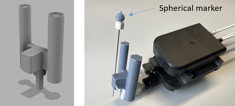
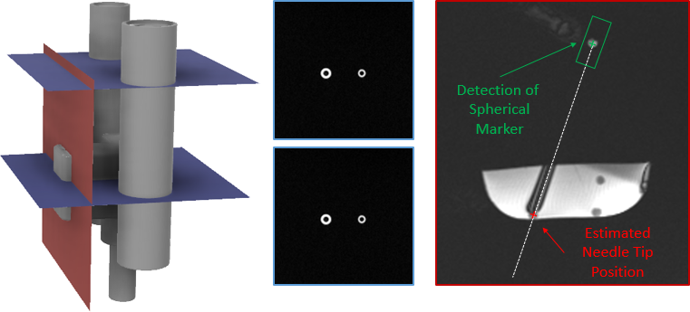
For position detection with the sequence an end-effector (Fig.1) was manufactured with two coaxial cylinders (small/large cylinder: inner diameter=5/6.5mm, outer diameter=10/13mm) with a displaced channel for needle guidance (distance=20 mm) using masked stereolithography (Prusa SL1, Prusa Research, Prague, Czech Republic). Additionally, a hollow sphere (Fig.1, inner diameter=8mm) was 3D-printed and fixed to the handle of a MR-compatible needle (length=95mm,diameter=16G; Somatex GmbH, Teltow, Germany). The sphere and the coaxial cylinders were filled with a contrast agent solution (Magnevist®/H2O=1/200, Bayer Schering Pharma AG, Berlin, Germany) for MR visualization. The end-effector was then attached to a mechanical assistance system (GantryMate, iSys, Kitzbühel) that allows needle manipulations from outside the magnet bore through extension rods10 (Fig.1).Detection of the end-effector is performed with a POCC sequence4–8 that acquires two FLASH tracking images of both cylinders such that they appear as rings with different diameters (Fig.2). In each tracking image$$$~I$$$, the position of the rings is determined using the POCC algorithm. Here, for each cylinder, a mask $$$~M$$$ is precomputed with the known physical dimensions and imaging parameters.
The POCC$$POCC(x,y)=\frac{I(x,y)}{\|I(x,y)\|}\ast\frac{M(x,y)}{\|M(x,y)\|}$$is calculated after Fourier-Transform in k-space representation using matrix multiplication. First, the POCC is calculated for the small marker and its position is determined with subpixel precision. Then, this position is nulled in image$$$~I$$$, and the position of the large ring is determined with an adapted mask image. Using the determined positions, the cylinder plane is calculated, and a targeting image is acquired coplanar to the needle with a balanced steady-state free precession (bSSFP) contrast.
In the targeting slice, a region of interest (ROI) is defined around the estimated position of the spherical marker (ROIlength=50mm,ROIwidth=12mm,ROIcenter=40mm above the center of both tracking slices). The magnitude values of all pixels within the ROI are projected to the needle trajectory, and the position of the spherical marker is determined from the maximum of this distribution. The known physical distance between the spherical marker and the needle tip (125mm) is then used to display the real position of the needle tip on the image (Fig.2). The cycle is repeated using the previously found ring coordinates and the position of the spherical marker as the center of the search ROI.
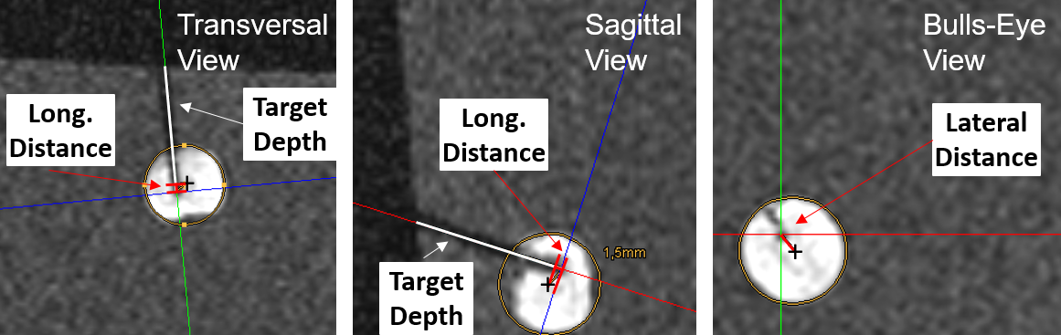
The sequence was implemented on a 1.5T system (Magnetom Aera, Siemens Healthineers, Erlangen, Germany). To perform needle insertion experiments, the assistance system was placed with the end-effector above a phantom containing 13 fiducial targets. A head coil was used for signal reception. For each target, the needle trajectory was aligned from a central position in real-time in two orthogonal views (parameter:TR/TE=3.0/1.5ms,BW=1530Hz/px,SLbSSFP=4.5mm,SLFLASH=10mm,FOV=300×300mm,matrix=192x144,TACycle=1.3s). Afterwards, the needle was inserted until the displayed needle tip position reached the target center (Fig.3). After all targets were punctured, a high-resolution data set (3D-GRE, resolution=0.25mm³) was acquired and the accuracy was evaluated in a reformatted view. Here, each target was approximated by a circle and the longitudinal accuracy was measured along the needle axis as the distance of the needle pathway to the nominal center (Fig.4). The lateral targeting accuracy was determined from the distance of the insertion to the nominal center in a bulls-eye view.
Results
All 13 targets could be punctured successfully using the end-effector in combination with the sequence. For a target diameter of 7.9±0.7mm and an insertion depth of 27.2±14.4mm, a lateral accuracy of 1.1±0.7mm and a longitudinal accuracy of 1.2±0.7mm was measured.Discussion & Conclusion
The results show the method can reliably determine the needle tip position without any hardware modifications. The experiment was performed in a controlled setting with a homogeneous phantom. More realistic scenarios have to be studied, taking into account needle deflections. Here, the simultaneous acquisition of two orthogonal slices11 would allow to detect deviations. In conclusion, estimation of the needle tip position improves the planning of the needle pathway in percutaneous interventions.Acknowledgements
This work was supported in parts by a grant from the German Federal Ministry for Economic Affairs and Energy (BMWi) under the grant program “Zentrales Innovationsprogramm Mittelstand (ZIM),” grant number ZF4535603BA9, as part of the IraSME funding “E‐GantryMate.”References
1. Busse, H., Kahn, T. & Moche, M. Techniques for Interventional MRI Guidance in Closed-Bore Systems. Top. Magn. Reson. Imaging 27, 9–18 (2018).
2. Lüdeke, K. M., Röschmann, P. & Tischler, R. Susceptibility artefacts in NMR imaging. Magn. Reson. Imaging 3, 329–343 (1985).
3. Ladd, M. E. et al. Biopsy needle susceptibility artifacts. Magn. Reson. Med. 36, 646–651 (1996).
4. de Oliveira, A., Rauschenberg, J., Beyersdorff, D., Semmler, W. & Bock, M. Automatic passive tracking of an endorectal prostate biopsy device using phase-only cross-correlation. Magn. Reson. Med. 59, 1043–1050 (2008).
5. Krafft, A. J. et al. Passive marker tracking via phase-only cross correlation (POCC) for MR-guided needle interventions: Initial in vivo experience. Phys. Med. 29, 607–614 (2013).
6. Zamecnik, P. et al. Automated Real-time Needle-Guide Tracking for Fast 3-T MR-guided Transrectal Prostate Biopsy: A Feasibility Study. Radiology 273, 879–886 (2014).
7. Reichert, A. et al. Simultaneous slice excitation for accelerated passive marker tracking via phase-only cross correlation (POCC) in MR-guided needle interventions. Magn. Reson. Mater. Phys. Biol. Med. 31, 781–788 (2018).
8. Reichert, A., Reiss, S., Krafft, A. J. & Bock, M. Passive needle guide tracking with radial acquisition and phase-only cross-correlation. Magn. Reson. Med. 85, 1039–1046 (2021).
9. Reichert, A. & Bock, M. MRI Needle Tracking with Phase-only Cross-Correlation (POCC) in the Presence of Susceptibility Artifacts. in Proc. Intl. Soc. Mag. Reson. Med. vol. 29 (2021).
10. Reichert, A., Bock, M., Vogele, M. & Joachim Krafft, A. GantryMate: A Modular MR-Compatible Assistance System for MR-Guided Needle Interventions. Tomography 5, 266–273 (2019).
11. Krafft, A. J., Rauschenberg, J., Maier, F., Jenne, J. W. & Bock, M. Crushed rephased orthogonal slice selection (CROSS) for simultaneous acquisition of two orthogonal proton resonance frequency temperature maps: CROSS Temperature Mapping. J. Magn. Reson. Imaging 38, 1510–1520 (2013).
Figures