1095
Acoustically-transparent passive RF field repeater elements for the mitigation of the low-signal artifact and improved sensitivity in MRgFUS1Department of Radiology, Weill Cornell Medicine, New York, NY, United States, 2GE Healthcare, Aurora, OH, United States, 3Department of Neurological Surgery, Weill Cornell Medicine, New York, NY, United States
Synopsis
MRgFUS image quality remains poor and suffers from a low-signal band artifact, preventing efficient image acquisition. We propose to place overlapped acoustically transparent loop elements in “passive mode” between the transducer and the head that act as a transmit field repeater/concentrator. Simulation results not only show mitigation of the low-signal band artifact in the thalamus region, but also demonstrate improvement of the RF transmit signal by a factor of 5 and 2 in the upper brain and the thalamus region, respectively.
Introduction
Despite the success of magnetic resonance-guided focused ultrasound (MRgFUS) in treating neurodegenerative diseases1, the poor imaging quality in many current MRgFUS examinations prevents efficient and rapid image acquisition. First, a typical birdcage-like head receive-coil cannot be used to achieve signal-to-noise-ratio (SNR) typically observed in MRI because the transducer does not leave adequate space. As a result, most MRgFUS techniques currently use the much larger and less efficient, vendor built-in, body-sized coil for both transmission and reception. Second, the high dielectric permittivity of the water bath that shortens the traveling RF wave together with the conductive surface of the transducer causes the incident and reflected RF signals propagating toward and from the brain to cancel each other. The destructive interference is known as a low-signal band artifact and occurs in the central region of the brain, around the thalamus, which is the region of interest for patients with essential tremors. A number of methods have been proposed to improve the MR signal by shifting the position of the low signal artifact2,3. However, the evaluation of their acoustic footprint has not been tackled.In previous work, we developed a very thin and flexible coil concept (FUS-Flex)4-6 with acoustic transparency as high as 97% at 650 kHz. In this study, we propose to place a pair of these acoustically transparent FUS-Flex coils in “passive mode” in the water bath between the transducer and the head. These passive loops pick up the fields generated by the body coil and act as a repeater/concentrator, which in turn mitigates wave cancellation. Unlike other methods proposed in the literature2,3, these passive elements (1) do not only restore the low-signal band but instead increase the transmit signal near the elements further due to their functionality as a field repeater/concentrator. Moreover, (2) previous acoustic optimization of the FUS-Flex concept6 ensures minimal target focus shift during sonication. A simulation study of different coil layouts is presented.
Methods
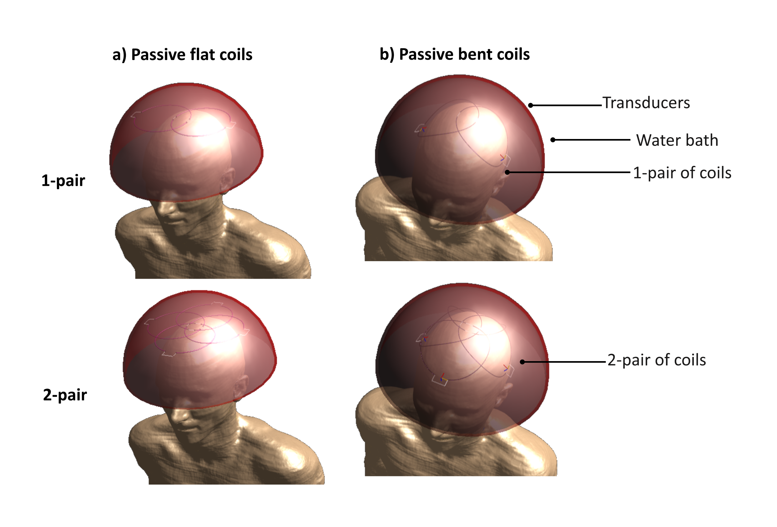
Electromagnetic simulations of 1- and 2-element pairs of passive elements were performed using Sim4Life. Each RF element used a diameter of 110 mm, which corresponds to half a wavelength at 3T in water. The pair was placed inside the water-filled transducer above the head of a virtual body model, Duke (IT’IS). The transducer was modeled using a 30-cm diameter semispherical water-filled copper-coated geometry. The element composition is described in references4,5. The elements were tuned to 128MHz and decoupled in order to act as a field concentrator. The tuning capability was added to each passive loop to enhance B1+ uniformity. The transmit performance due to the presence of the loops inside the water bath in flat and bent layouts was studied (Figure 1). A series of positions (D, in mm) between the head and the top of the transducer was investigated. A 16-leg body coil (diameter: 620 mm; length: 570 mm) was used for RF transmission, and B1+ maps were plotted. Finally, the specific absorption rate (SAR) was simulated with and without the passive elements.Results
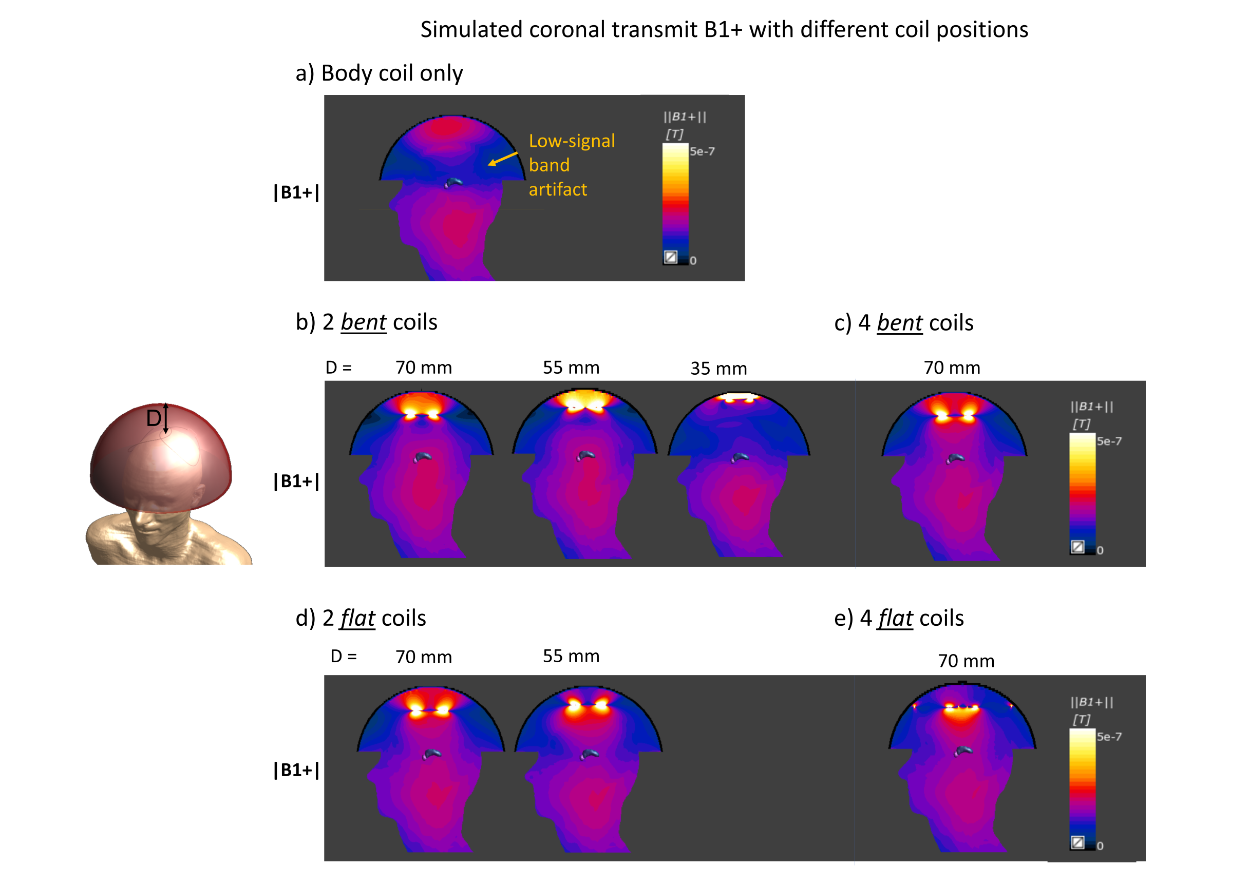
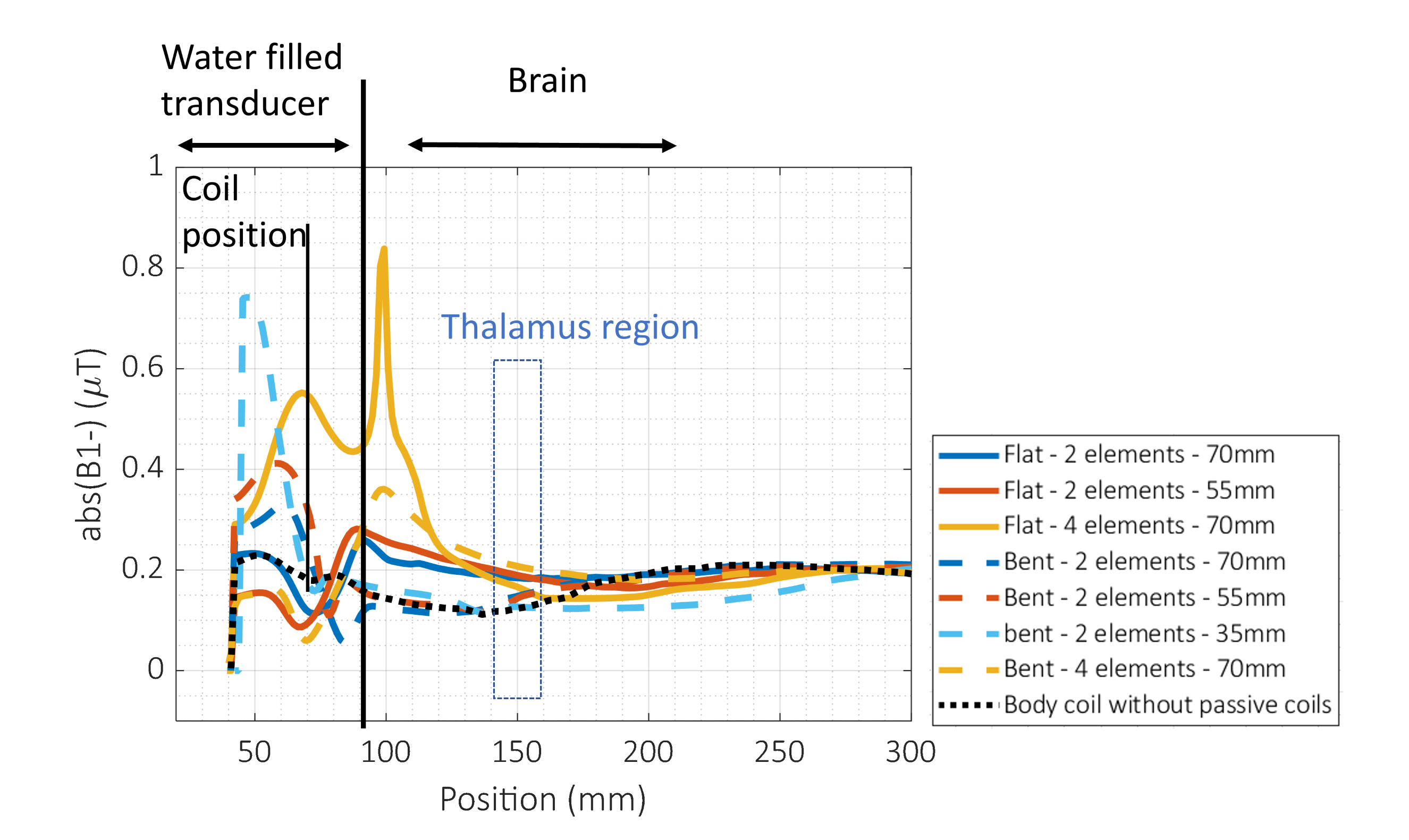
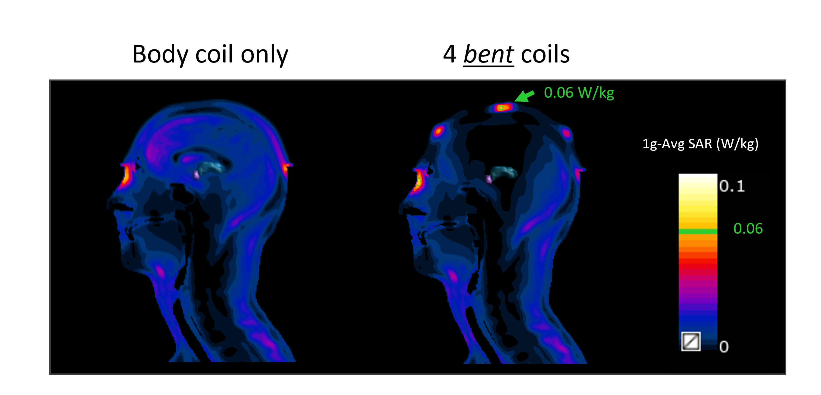
Figure 2a shows the low-signal band artifact around the thalamus region when only the body coil is used. Using a pair of passive elements moves the band artifact away from the brain, towards the top of the transducer. For both bent and flat 2-element configurations, the B1+ amplitude is highest when the coil is 70 mm away from the transducer. When the elements are placed closer to the transducer (angled, 35 mm), the artifact is still located partially inside the anatomy (Figure 2b). The 4-element flat RF loops show significant upper brain improvement in B1+ amplitude (5×/1.3× in upper brain/thalamus) compared to the body coil and good homogeneity (Figures 2,3). The 4 bent elements allow for higher B1+ focusing in deeper areas (3×/2× increase of B1+ at the upper brain/thalamus). A slight 1g-SAR increase was observed with a maximum of about 0.06W/kg near the elements (figure 4); its optimization is subject of future work.Conclusions
In this study, we aim to alleviate the low-signal band artifact in one apparatus by presenting a very thin, acoustically transparent pair of overlapped passive elements acting as field concentrators/repeaters. A simulation study using 1 and 2 pairs of passive elements was conducted and shows the shift of the artifact as well the improvement of B1+ by a factor of 2 and 5 at the thalamus region and in the upper brain, respectively. The choice of flat vs bent configuration is determined by the depth of the target region. The very thin (~1mm) RF elements provide low shoot through interaction with the acoustic field unlike other proposed methods in the literature and can be placed safely inside the water bath. Future work will involve testing the passive coils in vivo during an MRgFUS procedure and combining them with an “active” receive-only FUS-Flex high-channel-count array to further increase the image quality. From prior work, we obtain an estimated ~40× SNR improvement combining the 10-channel 20× receive SNR increase6 with the 2x transmit field repeater, which could enable shorter scan times and enhanced intraprocedural imaging.Acknowledgements
This work was supported by NIH R00EB024341 and GE Healthcare.References
1. Chazen JL, Sarva H, Stieg PE, et al. Clinical improvement associated with targeted interruption of the cerebellothalamic tract following MR-guided focused ultrasound for essential tremor. Journal of Neurosurgery. 2018;129(2):315-323.
2. Hadley JR, Odéen H, Merrill R, et al. Improving image quality in transcranial magnetic resonance guided focused ultrasound using a conductive screen. Magnetic Resonance Imaging. 2021;83:41-49.
3. Yan X, Allen S, Meyer CH, Grissom WA. Improvements in in vivo imaging and temperature mapping using passive “propeller-beanie”antenna in transcranial MR-guided focused ultrasound. Paper presented at: In Proceedings of the Annual Meeting of ISMRM2021.
4. Saniour I, Robb F, Taaracila V, et al. Acoustically transparent and low profile head coil for high precision magnetic resonance guided focused ultrasound at 3T. Paper presented at: In Proceedings of the Annual Meeting of ISMRM2021.
5. Saniour I, Robb F, Taracila V, et al. Attenuation of the dark band artifact in MR-guided focused ultrasound using an ultra-flexible high-sensitivity head coil. Paper presented at: In Proceedings of the Annual Meeting of ISMRM 2021.
6. Saniour I, Robb F, Taracila V, et al. Improving image quality and acoustic transparency in MRgFUS at 3T using a low-profile, flexible receive coil array. Paper submitted at: In Proceedings of the Annual Meeting of ISMRM 2022.
Figures