1094
Construction of a Tx/Rx body coil on a rotatable patient capsule for MR-guided particle therapy1Medical Physics in Radiology, German Cancer Research Center (DKFZ), Heidelberg, Germany, 2Department of Radiation Oncology, Heidelberg University, Heidelberg, Germany, 3Faculty of Physics, Heidelberg University, Heidelberg, Germany, 4National Center for Radiation Research in Oncology (NCRO), Heidelberg, Germany, 5Heidelberg Institute of Radiation Oncology (HIRO), Heidelberg, Germany, 6National Center for Tumor Diseases (NCT), Heidelberg, Germany, 7German Cancer Consortium (DKTK), Heidelberg, Germany, 8Faculty of Medicine, Heidelberg University, Heidelberg, Germany, 9German Cancer Research Center (DKFZ), Heidelberg, Germany
Synopsis
An RF body coil compatible with particle therapy was built for a clinical MR scanner at 1.5T with a rotatable patient capsule. The attenuation of 1H+ and 12C6+ ions due to inelastic scattering was calculated for different materials to estimate the detrimental effects of the RF coil on the particle beam. The imaging capabilities could be demonstrated with phantom measurements at different flip angles, and corresponding transmit and receive characteristics were analyzed and compared to electromagnetic field simulations for both a horizontal and a tilted position of a phantom.
Introduction
As recent studies indicate, MR-guided radiotherapy (MRgRT) harbors great potential as an alternative to conventional CT-guided radiotherapy1. Alongside better soft tissue contrast, NMR provides an imaging method without ionizing radiation. Imaging between irradiation fractions or real-time gating could permit modifications to the treatment plan and lead to adaptive radiotherapy. This concept can also be applied to particle therapy, which has the potential to further reduce the dose exposure to the patient2. Therefore a hybrid device comprising a treatment table in an MR scanner with access of the ion beam to the patient would be favorable. However, this configuration puts strict conditions on the MR system and its components. The ion beam must not be affected by the RF coil, since scattering or unknown attenuation may impair the treatment. Ideally, the patient table provides access from several angles to be more flexible in the treatment planning. Even for static ion beams, this could be realized with a rotatable patient capsule. Moreover, uniform and homogeneous RF transmit field characteristics over a large FOV are necessary for reliable tissue classification. In this work, an RF body coil with minimal water equivalent thickness (WET) was designed and constructed for a clinical MR scanner at 1.5T.Methods
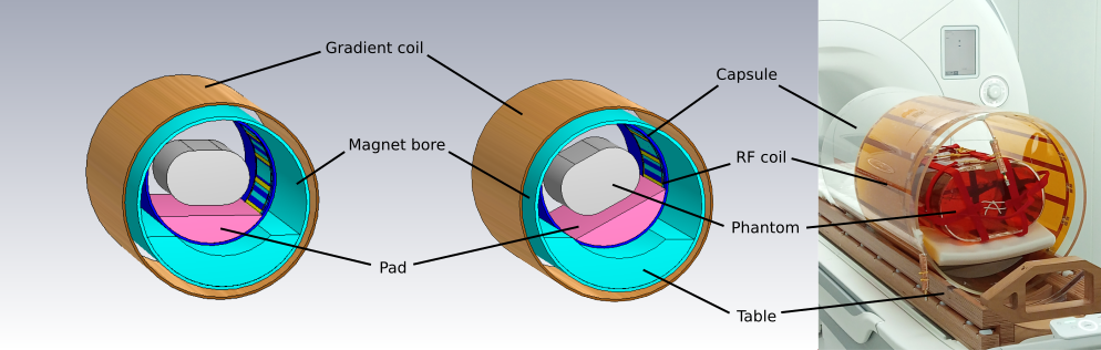
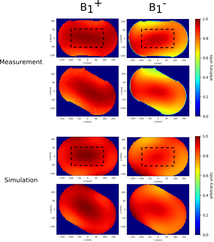
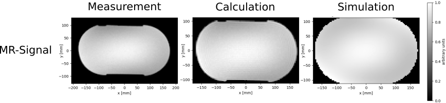
Coil: A single channel Tx/Rx 16-leg high-pass birdcage configuration3,4 with total length of 520mm was chosen to achieve high RF field homogeneity. The coil is attached to the inner surface of an acrylic glass cylinder with an inner diameter of 530mm and consists of copper with a thickness of 35µm covered between two sheets of polyimide and multiple layers of acrylic glue. While the supporting components of the coil and the capsule can be built homogeneously and corrected for in the treatment plan, sharp edges near the conductor or at electronic components pose a bigger obstacle. For that reason, all conductors and other electronic devices (quadrature hybrid, Tx/Rx switch, cables,..) are located at the end rings. The WET of the conductor was calculated for protons and 12C6+ ions in the clinical energy range of (48-221)MeV and (88-430)MeV/u respectively via the Bethe-Bloch formula5 to estimate the beam interaction with the coil. MR scanner: All measurements were performed on a 1.5T whole-body MR system (Sola, Siemens Healthcare, Erlangen, Germany). B1+ mapping was performed using the double-angle method6 with the following sequence parameters: 2 acquisitions with GRE sequence: TE=10ms, TR=10s, in-plane resolution=(3.75mm)², slice thickness=5mm, RF spoiling; 1st pulse voltage=150V; 2nd pulse voltage=300V. For comparison, an MR image was acquired with a pulse voltage of 200V with equal parameters except for a resolution of (3.2mm)²×(5mm). Additionally, the coil performance was examined with the ellipsoidal phantom rotated 30° within the capsule as detuning of the body coil could deteriorate its imaging capabilities. Phantom: A phantom of size 500×350×200mm3 is filled with a mixture of water, sodium chloride and polyvinylpyrrolidone (PVP) to imitate the mean permittivity (εr=47) and mean conductivity (σ=0.42$$$\frac{S}{m}$$$) of the human torso at 64MHz; these values were extracted from a human voxel phantom (Gustav) in simulation. Simulation: Crucial parts of the setup (see Fig. 1) were implemented in a simplified model to perform electromagnetic field simulations in CST Studio Suite 20207 from 0 to 150MHz. Insulating materials were specified as acrylic glass (εr=2.8, tan(ẟ)=0.02 (1MHz)).The mesh for the finite element calculation covers the structure with approximately 20 million cells, including an enhanced resolution of 2mm in the vicinity of the RF coil. Imaging: The relationship between MR signal and relative RF field distributions is as follows: $$$S(\vec{x})\sim sin(α(\vec{x}))×B_{1,~rel}^{-}(\vec{x})$$$ with flip angle $$$α(\vec{x})\sim B_{1,~rel}^{+}(\vec{x})$$$. Given the transmit field and the MR signal for a specific flip angle, the receive field distribution (see Fig. 2) or vice versa the MR signal was calculated (see Fig. 3).Results
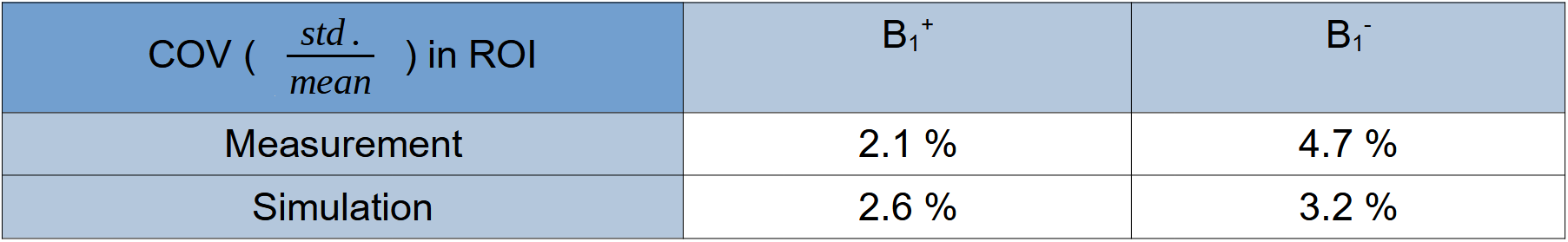
For both protons and 12C6+ ions, the WET of the conductor in the RF coil is less than 215µm in the applied energy range and thus is deemed negligible for treatment planning. In Fig. 2 the transmit and receive fields are illustrated for a transversal slice of the phantom in the magnet center. Good field homogeneity was achieved for 0° and 30° rotation of the phantom with slight field asymmetries, especially at the edges of the phantom. However, the RF fields from measurement and simulation show similar distributions. The coefficient of variation (COV) values in Fig. 4 quantitatively confirm the uniformity of the B1+ and B1- fields and the agreement between measurement and simulation. Fig. 3 shows MR images of the homogeneous phantom and the similarity between directly measured, scaled, and purely simulated data.Discussion & Conclusion
The built RF coil provides a concept for MRgRT with particles while maintaining good imaging characteristics at 64MHz with little asymmetries comparable to those reported in literature8,9. As the coil is capable of both transmitting and receiving MR signals, additional receive coils can be omitted, facilitating particle therapy by avoiding the effect of additional hardware on the ion beam. To achieve higher flexibility in therapy, a large range of rotation angles would be beneficial. Therefore, further investigation of the angular dependence of the RF field homogeneity will be performed in future experiments with the presented setup.Acknowledgements
This work received financial support from the German Federal Ministry of Education and Research (BMBF, ARTEMIS project WP8, funding reference 13GW0436B)References
1Pollard J. M. et al.,
"The future of image-guided radiotherapy will be MR guided",
The British Institute of Radiology (2017)
2Hoffmann A., et al.,
"MR-guided proton therapy: a review and a preview",
Radiation Oncology 15 (2020); 1-13
3Tropp J., "The
theory of the bird-cage resonator", Journal of Magnetic
Resonance (1989); 82:51-62
4Hayes C. E. et al.,
"An efficient, highly homogeneous radiofrequency coil for
whole-body NMR imaging at 1.5T", Journal of Magnetic Resonance
(1985); 63:622-628
5Bloch, F., "Zur
Bremsung rasch bewegter Teilchen beim Durchgang durch die Materie",
Annalen der Physik (1933); 16,
285.
6Insko
E. K., Bolinger L., "Mapping of the radiofrequency field.",
Journal of Magnetic Resonance (1993); 103:82-85.
7"CST Studio
Suite 2020", Dassault Systèmes, Vélizy-Villacoublay, France
8Vaidya M. V. et al.,
"Dependence of B1+ and B1- field patterns of surface coils on
the electrical properties of the sample and the MR operating
frequency", Concepts in Magnetic Resonance Part B (2016);
46:25-40
9Cloos M. A. et al.,
"Multiparametric imaging with heterogeneous radiofrequency
fields", Nature Communications (2016); 7:12445
Figures