1090
16-Channel Hybrid Dipole+Loop RF Applicator for Thermal MR at 7.0 Tesla1Berlin Ultrahigh Field Facility (B.U.F.F.), Max-Delbrück Center for Molecular Medicine in the Helmholtz Association, Berlin, Germany, 2MRI.TOOLS GmbH, Berlin, Germany, 3MT MedTech Engineering GmbH, Berlin, Germany, 4Technische Universität Berlin, Chair of Medical Engineering, Berlin, Germany, 5Experimental and Clinical Research Center (ECRC), a joint cooperation between the Charité Medical Faculty and the Max-Delbrück Center for Molecular Medicine in the Helmholtz Association, Berlin, Germany
Synopsis
This work proposes the concept of a loop and SGBT dipole antenna array for diagnostic proton (1H) imaging and thermal intervention at 7.0T MRI. Dipole antennas are the general choice for RF induced heating application as they can be made to operate over a broadband frequency range, have symmetric B1+ field and provide a central E-field distribution. Adding the inherently orthogonal and thus well-decoupled electromagnetic (EM) fields of loops to the dipoles provides additional degrees of freedom for RF shimming and thermal intervention not afforded by only using dipole antennas.
Purpose
Clinical benefits have been reported for localized thermal therapy as a potent sensitizer of chemo and radiotherapy for various cancers1-5 and for assisting targeted drug delivery using thermo-responsive nano-carriers6. In thermal magnetic resonance (Thermal MR), an integrated RF applicator is used to support diagnostic imaging, MR thermometry and RF induced heating for targeted temperature manipulation7.The potential of dipole antennas for Thermal MR and RF induced targeted heating is well recognized but the additional value of loop elements remains to be investigated. Dipole antenna offers more uniform B1+ fields and improved penetration depth compared to loop at UHF 8,10–14. Loop antennas are single frequency resonant, show asymmetric B1+ field distribution at UHF and provide E-fields on surface10-11. Recognizing the properties of loop and dipole, this work examines a 16-channel hybrid dipole+loop RF applicator concept for Thermal MR at 7.0 Tesla, which improves the feasible channel counts and offers additional degrees of freedom for RF shimming and targeted heating. For this purpose, an annular RF array is proposed that combines the compact SGBT building block8, with loop elements.Methods
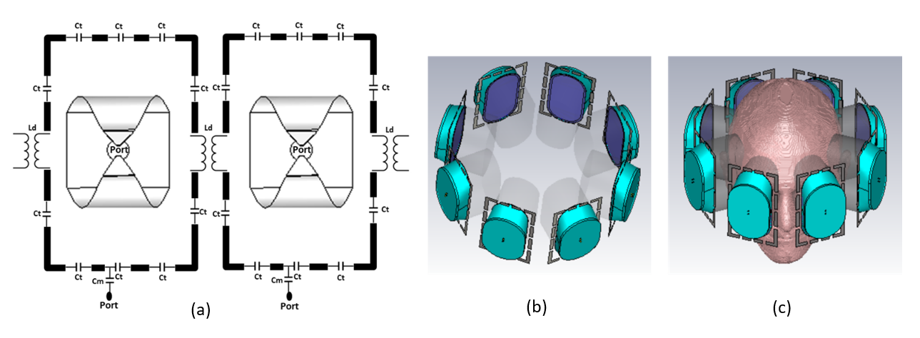
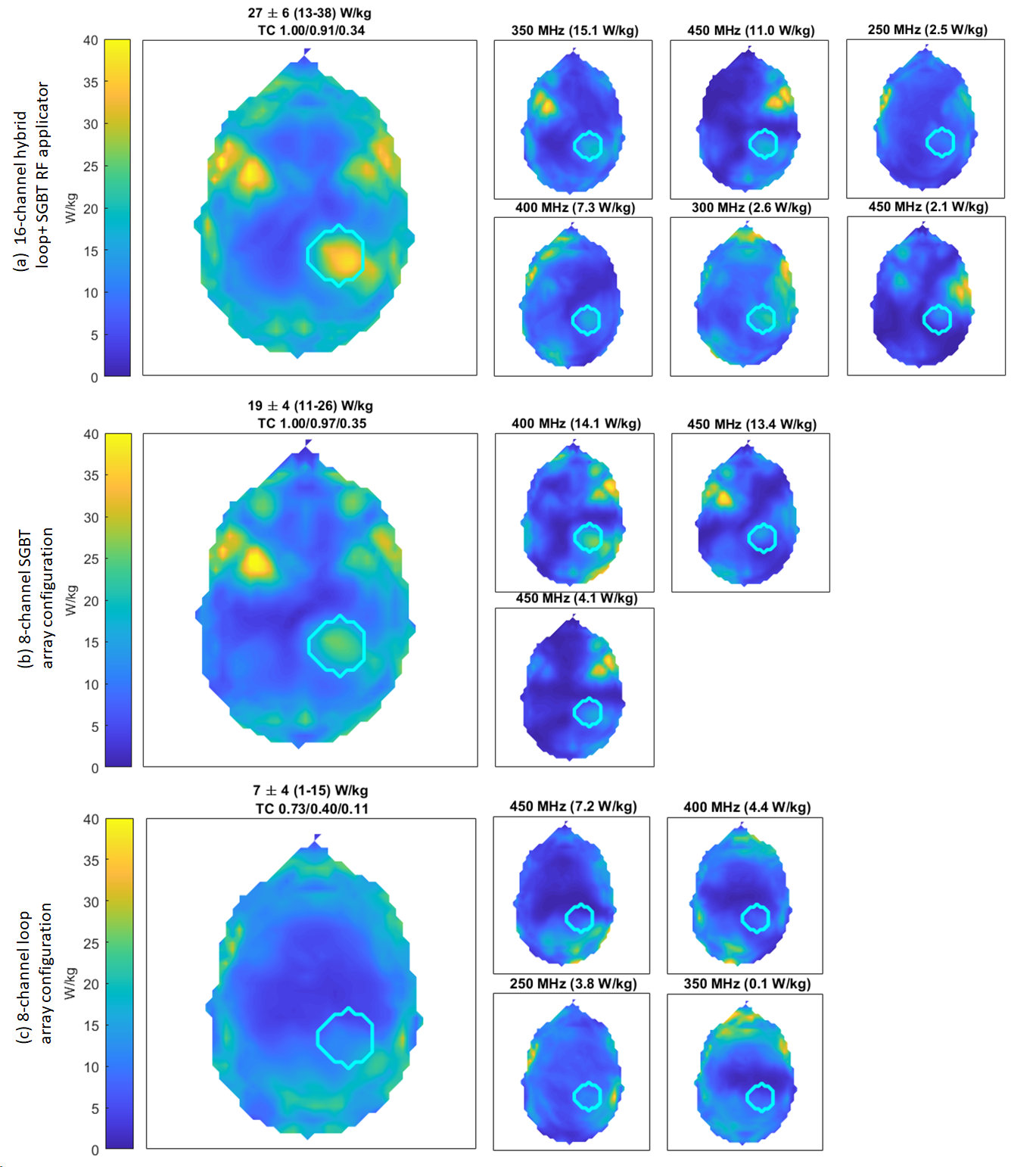
An annular RF array that combines eight compact SGBT8 antenna (42.3x46.3 mm) with eight rectangular loop elements (75x125 mm) was designed (Figure 1) to support MRI at 300MHz (B0 = 7.0 T) and RF heating induced thermal intervention using multiple discrete frequencies 250, 300, 350, 400, 450 MHz. The 8 SGBT dipoles were fed at the center. Each SGBT dipole uses a water bolus placed between the radiating element and the surface of the object under investigation to enhance the efficiency and directivity for targeted RF heating. Loops were fed with a capacitive matching network and tuned to be multi-resonant to work with broadband SGBT dipoles at frequencies of 250MHz, 300MHz, 350MHz, 400MHz, 450MHz. The loops are decoupled to each other with a transformer decoupling16. Electromagnetic field (EMF) simulations (CST Studio Suite 2020, Dassault, Darmstadt, Germany) were performed on the human voxel model ‘Duke’ of the virtual family15(IT’IS Foundation Zürich, Switzerland). To mimic a clinical scenario the Duke model was modified with an intracranial sphere r= 2cm radius that represents a small tumor (r = 2cm, σtumor = 1.15S/m, εrtumor = 66.5) in the right parietal region of the brain with a target volume of 33.5ml1. Postprocessing was conducted (MATLAB 2020, The Mathworks, Natick, CA, USA) to calculate B1+ field, SARavg,10g and targeted heating optimization. For the targeted heating, a time and frequency multiplexed RF-induced heating algorithm9 was used. The optimization algorithm provided globally optimal excitation vectors defining the phase and amplitude setting for each RF channel, automatically selecting the appropriate frequencies and time-interleaved excitations. The resulting SAR distribution is tailored for heating the target volume with the goal to reduce RF exposure to healthy tissues. The desired target SAR was set to 100 W/kg in order to maximize RF power deposition inside the tumor target volume (TV). SAR was constrained to 40 W/kg for regions outside of the TV.Results
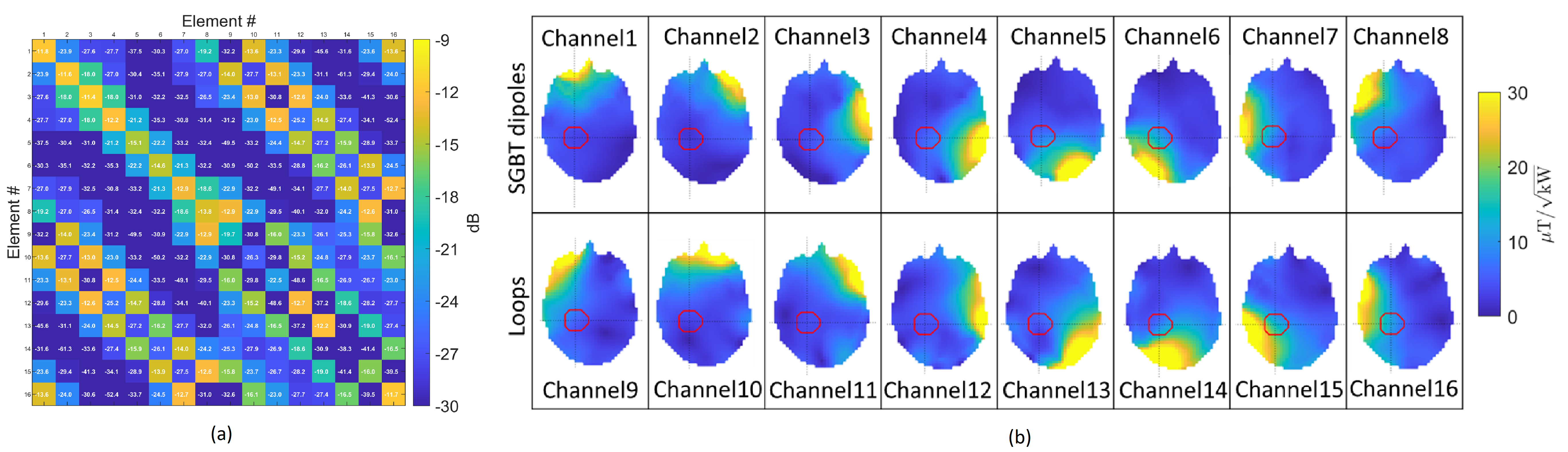
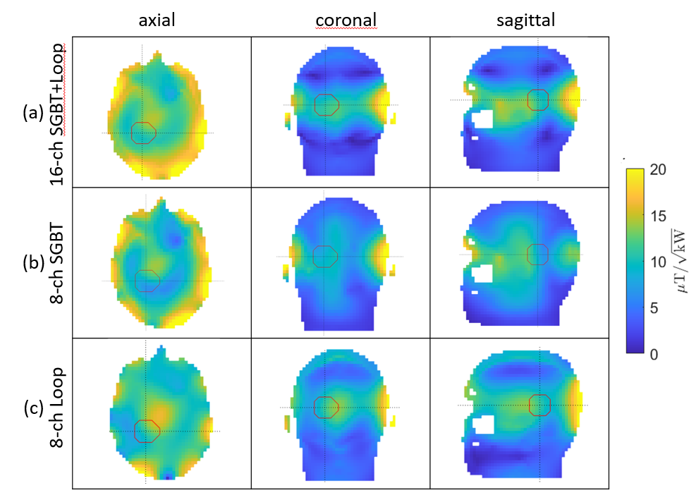
The EMF simulations demonstrate (Figure 3) that the hybrid 16-channel SGBT+loop RF applicator provides improved B1+ efficiency and homogeneity over whole brain compared to a setup with only 8-channel SGBT or 8-channel loop array using circular polarised mode for MRI at 7.0T. Figure 4, shows the scattering matrix obtained for the 16-channel hybrid SGBT+loop RF applicator at 300MHz. The optimization algorithm identified six excitation modes at frequencies of 250, 300, 350, 400 and 450MHz as the optimum solution (Figure 5). These six excitations provided strong focal heating in the tumor region. For targeted RF heating (Figure 5), the 16-channel hybrid SGBT+loop RF applicator yielded an increase in mean and maximum SARavg,10g over only using the 8-channel SGBT dipole antennas or the 8-channel loop antennas. The SGBT+loop hybrid provided a mean and maximum SARavg,10g of 27 and 38 W/kg. The 8-channel SGBT array configuration provided a mean and maximum SARavg,10g value of 19 and 26 W/kg in the target volume. The 8-channel loop array excitation revealed a mean and maximum SARavg,10g of 7 and 15W/kg for peripheral brain regions outside of the tumor model.Discussion and Conclusion
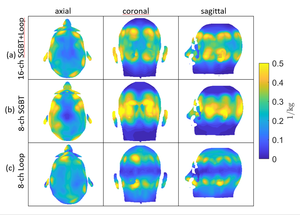
This work demonstrates the feasibility of a 16-channel hybrid RF applicator combining loop elements and compact SGBT antenna for MRI at 7.0T and thermal intervention in an integrated device. Our findings show that the hybrid SGBT+loop RF applicator provides enhanced RF power deposition in the target volume with mean SARavg,10g being ~42% superior to an 8-channel SGBT array. To conclude, the hybrid RF applicator is able to form a stronger SAR focus in the tumor TV. This achievement highlights that loop elements benefit RF power deposition inside the target region. Our simulations showed a conjugate hotspot for peripheral regions of facial muscle of the head. This unwanted effect is due to the strong E-fields of the SGBT antenna placed in close proximity of these anatomic regions. This adverse effect can be addressed with high-density SGBT+loop arrays that facilitate extra degrees of freedom for more excitations tailored for more focused heating of the target volume. An elliptical array configuration covering the head excluding the frontal area (2700 coverage) constitutes an alternative solution over an annular array (whole head coverage, 3600).Acknowledgements
This project was funded in part by an advanced ERC grant (EU project Thermal MR: 743077).References
1. Oberacker E, Kuehne A, Oezerdem C, Nadobny J, Weihrauch M, Beck M, Zschaeck S, Diesch C, Eigentler TW, Waiczies H, Ghadjar P, Wust P, Winter L, Niendorf T. Radiofrequency applicator concepts for thermal magnetic resonance of brain tumors at 297 MHz (7.0 Tesla). Int J Hyperthermia. 2020;37(1):549-563.
2. Wust P, Hildebrandt B, Sreenivasa G, Rau B, Gellermann J, Riess H, Felix R, Schlag PM. Hyperthermia in combined treatment of cancer. Lancet Oncol 2002;3(8):487-497.
3. Horsman MR, Overgaard J. Hyperthermia: a potent enhancer of radiotherapy. Clin Oncol (R Coll Radiol) 2007;19(6):418-426.
4. Issels RD, Lindner LH, Verweij J, Wust P, Reichardt P, Schem BC, Abdel-Rahman S, Daugaard S, Salat C, Wendtner CM. Neo-adjuvant chemotherapy alone or with regional hyperthermia for localised high-risk soft-tissue sarcoma: A randomised phase 3 multicentre study. Lancet Oncol 2010;11(6):561-570.
5. Lee Titsworth W, Murad GJ, Hoh BL, Rahman M. Fighting fire with fire: the revival of thermotherapy for gliomas. Anticancer Res 2014;34(2):565-574.
6. Ji Y, Winter L, Navarro L, Ku MC, Periquito JS, Pham M, Hoffmann W, Theune LE, Calderón M, Niendorf T. Controlled Release of Therapeutics from Thermoresponsive Nanogels: A Thermal Magnetic Resonance Feasibility Study. Cancers (Basel). 2020 May 27;12(6):1380.
7. Winter L, Özerdem C, Hoffmann W, et al. Design and Evaluation of a Hybrid Radiofrequency Applicator for Magnetic Resonance Imaging and RF Induced Hyperthermia: Electromagnetic Field Simulations up to 14.0 Tesla and Proof-of-Concept at 7.0 Tesla. Yacoub E, ed. PLoS One. 2013;8(4):e61661.
8. Eigentler TW, Winter L, Han H, Oberacker E, Kuehne A, Waiczies H, Schmitter S, Boehmert L, Prinz C, Trefna HD, Niendorf T. Wideband Self-Grounded Bow-Tie Antenna for Thermal MR. NMR Biomed. 2020 May;33(5):e4274.
9. Kuehne A, Oberacker E, Waiczies H, Niendorf T. Solving the Time- and Frequency-Multiplexed Problem of Constrained Radiofrequency Induced Hyperthermia. Cancers. 2020; 12(5):1072.
10. Woo MK, DelaBarre L, Lee BY, Waks M, Lagore RL, Radder J, Eryaman Y, Ugurbil K, Adriany G. Evaluation of a 16-channel transceiver loop + dipole antenna array for human head imaging at 10.5 tesla. IEEE Access. 2020;8:203555-203563.
11. Raaijmakers AJ, Luijten PR, van den Berg CA. Dipole antennas for ultrahigh-field body imaging: a comparison with loop coils. NMR Biomed. 2016 Sep;29(9):1122-30.
12. Oezerdem C. et al., “16-channel bow tie antenna transceiver array for cardiac MR at 7.0 tesla,” Magn Reson Med, vol. 75, no. 6, pp. 2553–2565, 2016.
13. Lattanzi R, Wiggins GC, Zhang B, Duan Q, Brown R, and Sodickson DK, “Approaching ultimate intrinsic signal-to-noise ratio with loop and dipole antennas,” Magn Reson Med, vol. 79, no. 3, pp. 1789–1803, 3, 2018.
14. Pfrommer A, and Henning A, “The ultimate intrinsic signal-to-noise ratio of loop-and dipole-like current patterns in a realistic human head model,” Magn Reson Med, vol. 80, no. 5, pp. 2122–2138, 2018.
15. Restivo MC, van den Berg CAT, van Lier ALHMW, et al. Local specific absorption rate in brain tumors at 7 tesla. Magn Reson Med.2016;75(1):381–389.
16. Roemer PB, Edelstein WA, Hayes CE, Souza SP, Mueller OM. The NMR phased array. Magn Reson Med. 1990 Nov;16(2):192-225
Figures