1087
Water-Immersed 8-Dipole Receive Array for MR-Guided Focused Ultrasound of the Brain at 3T1Oncology, University of Alberta, Edmonton, AB, Canada, 2Electrical and Computer Engineering, University of Alberta, Edmonton, AB, Canada, 3Departments of Radiology and Clinical Neurosciences, Hotchkiss Brain Institute, University of Calgary, Calgary, AB, Canada, 4GE Healthcare Inc., Aurora, OH, United States, 5Medical Physics, Cross Cancer Institute, Edmonton, AB, Canada
Synopsis
The piezoelectric transducer array in magnetic resonance guided focused ultrasound shields the RF body-sized birdcage (BC) fields, leading to regions of low receive sensitivity that hinder MR thermometry and structural imaging. This work presents a flexible, acoustically transparent receive array consisting of dipole sections that mimic loops and are contained within the water bath of the ultrasound transducer array helmet surrounding the head. Adjacent elements are decoupled by shared current paths and lumped inductors. In simulation, the receive sensitivity is increased by 7.8-fold compared to a BC and causes a negligible alteration of the transmit field and specific absorption rate.
Introduction
Magnetic resonance guided focused ultrasound (MRgFUS) is performed using piezoceramic transducers covering the surface of a water filled hemispherical helmet placed over the head. The conductive backing on the transducers partially shields the electromagnetic fields, resulting in regions of low radio-frequency (RF) transmission and receive sensitivity of the transmit/receive body coil outside of the helmet. Positioning a receive coil inside the helmet, close to the head, will increase receive sensitivity and improve MR thermometry and structural imaging during the procedure. Previously, receive arrays outside of the helmet have been employed1, but they have lower sensitivity in the deep regions of the brain that are typically targeted with MRgFUS. A 2-coil array incorporated within the helmet and partially embedded in the water was found to improve the receive-sensitivity by a factor of 3-42, but the elements were bulky, the region of high sensitivity did not cover the entire head and more channels are needed to enable parallel imaging. Thus, the 8-element array design we propose uses acoustically transparent ultra-thin wiring, positioned in the water bath between the MRgFUS helmet and patients head. A novel dipole-loop-type configuration takes advantage of displacement currents in the water and minimizes the amount of acoustic interference.Methods
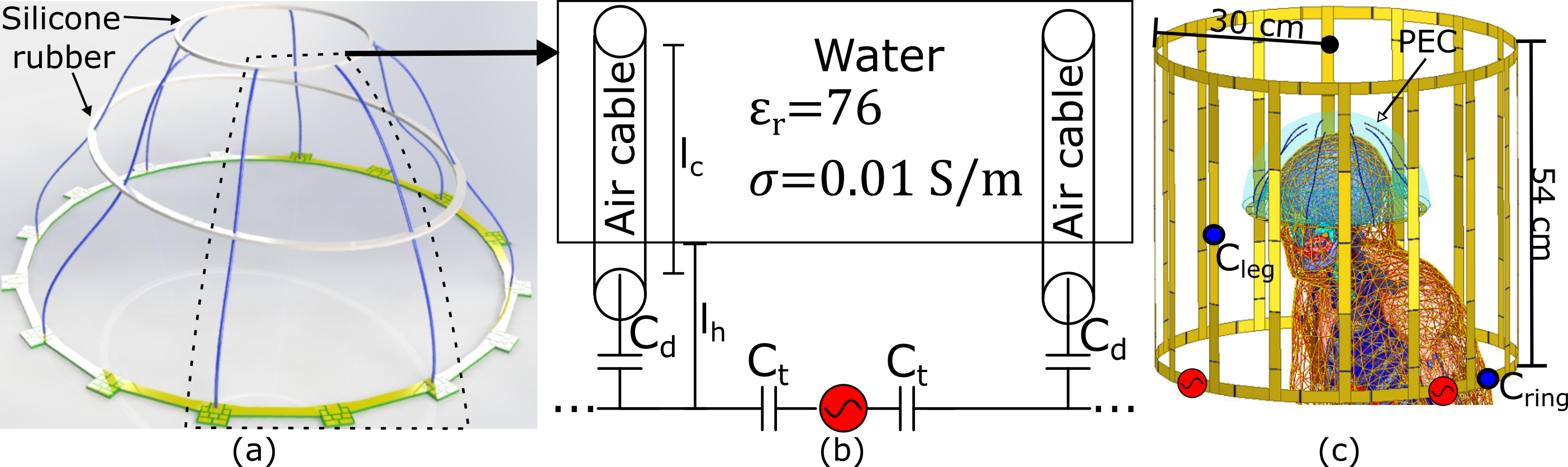
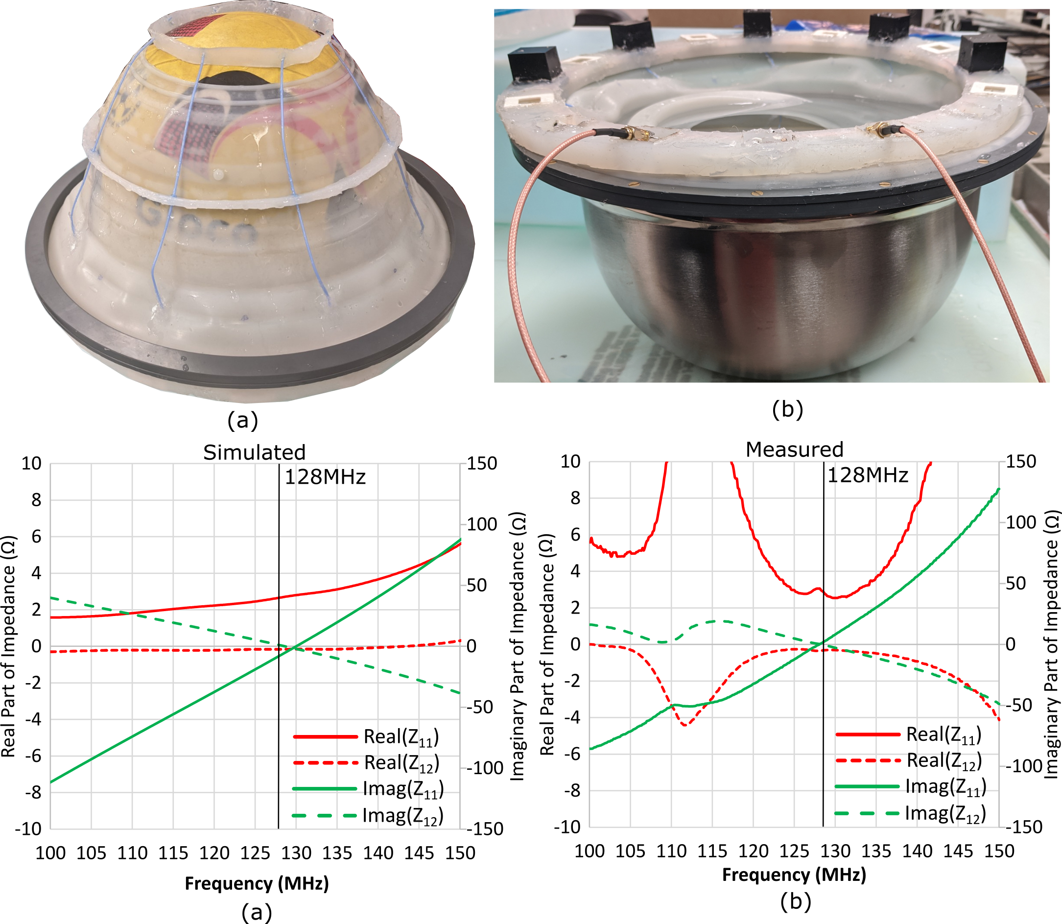
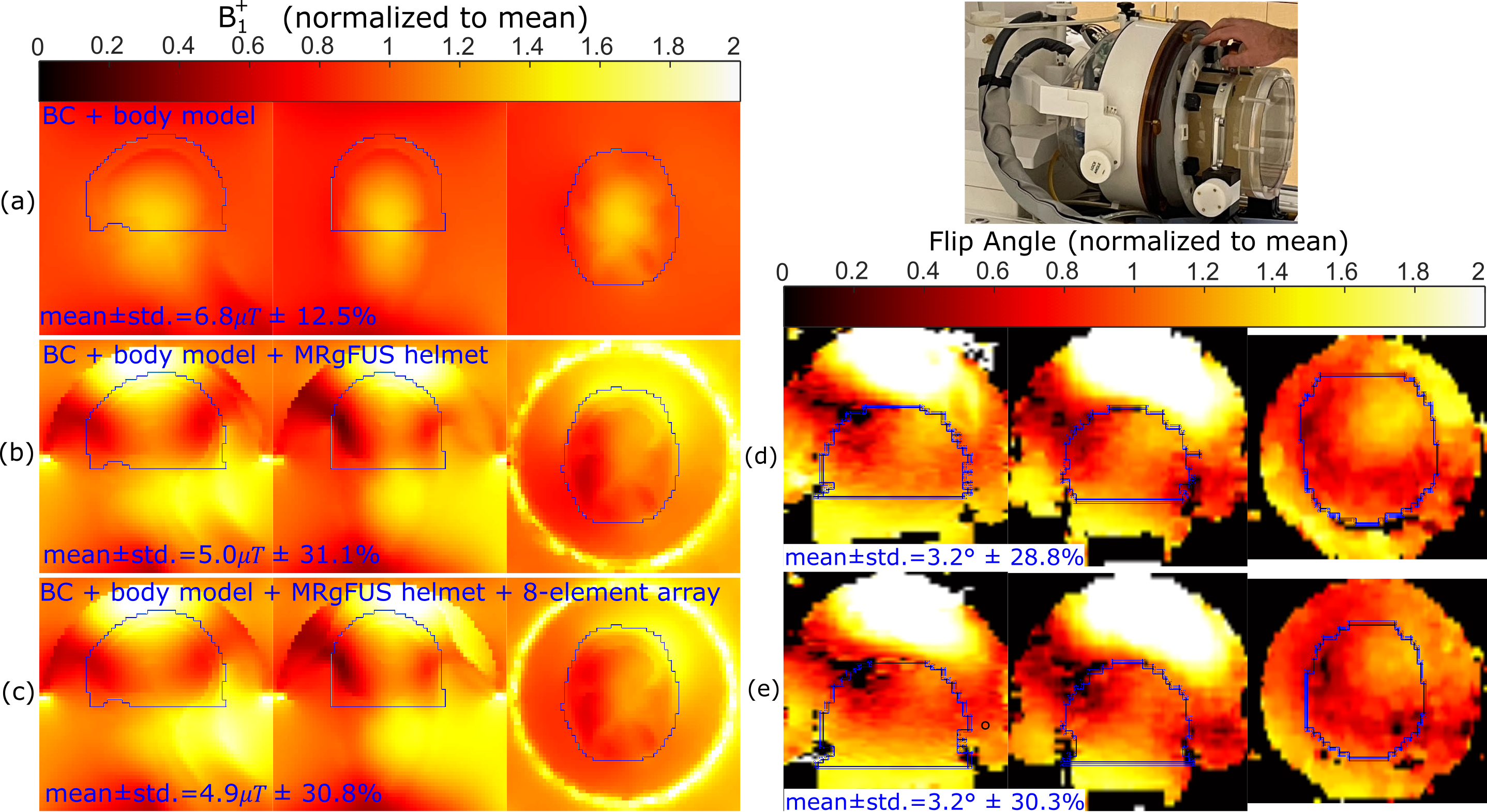
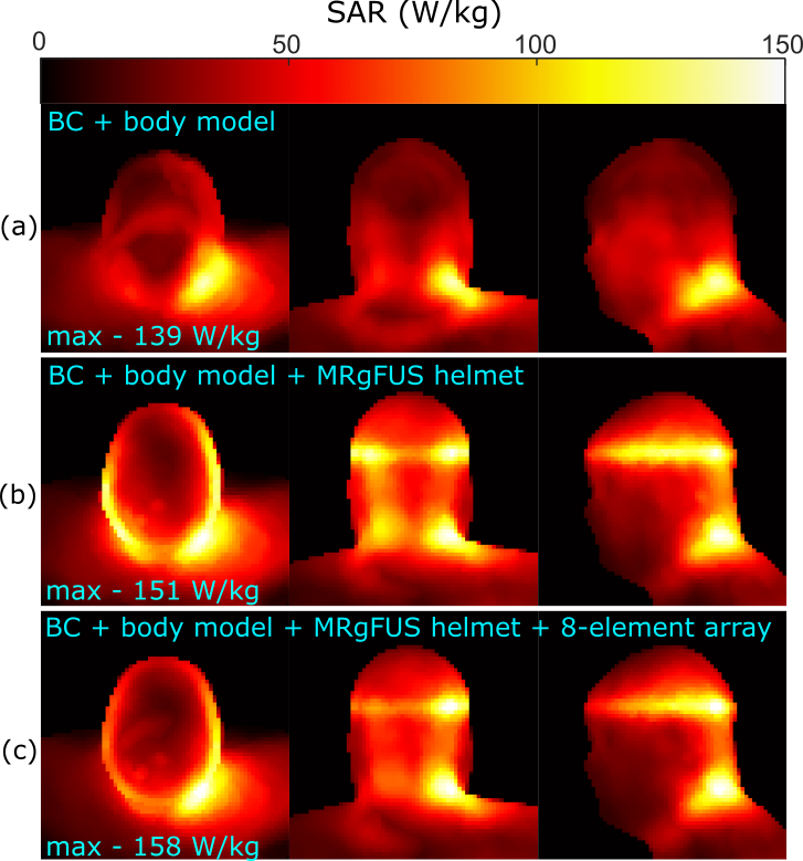
The geometry of the 8-element array is shown in Figure 1(a). A simplified circuit schematic of a single element is shown in Figure 1(b), which exemplifies the placement of tuning (Ct=44pF) and decoupling (Ld=25nH) inductors and the distance between the printed circuit board and the water (lh=10mm) and length of AirTM cables3,4 above the water (lc=16cm). The cables have been shown to be largely acoustically transparent5, are resistant to water and are flexible. The simulation model (Ansys, HFSS) of the array with human body model6, a hemisphere of water (the hemispherical curved surface is conductive) representing the MRgFUS helmet and body sized quadrature driven birdcage coil (BC) are shown in Figure 1(c) (Cleg=60pF, Cring=27.4pF). All conductors were modelled as copper (conductivity=5.8 S/m). The array shown in Figure 2(a) was constructed to match the simulation geometry; input impedance and mutual impedance were measured (set-up in Figure 2(b)) after tuning and decoupling to verify the low coupling and zero reactance achieved in the simulation. Due to the excitation of a dipole-like resonance, and inability to place detuning traps in the water bath, the distortion of the transmit field is quantified by simulation of the right circularly polarized magnetic field ($$$B_1^+$$$) with 1kW RMS input power, with and without the 8-element array. A blocking impedance of 1.5kΩ is placed at the ports to emulate detuning. Also, 2D Bloch-Siegert flip angle mapping7 was performed (3T, GE Discovery-MR750) with the MRgFUS helmet (Insightec, ExAblate 4000) and in-house-made head phantom, with and without the array. The elements were terminated with 1.8pF capacitors to emulate detuning. Imaging parameters were 31.25KHz BW, 64×64×60 matrix, 4.375x4.375x5mm3, TE=12.3ms, TR=29ms, 8ms pulse width and 4kHz offset frequency. The power deposited into the body resulting is restricted by safety regulations that limit the specific absorption rate (SAR)8. Thus, the 10g averaged SAR was simulated with and without the receive array. Finally, the simulated left circularly polarized magnetic field produce per unit current ($$$B ̂_1^-$$$) was used to calculate the intrinsic SNR with the BC acting as a single Tx/Rx coil with fixed phase combination or with the fields of the Rx array combined optimally, as in reference (9).Results and Discussion
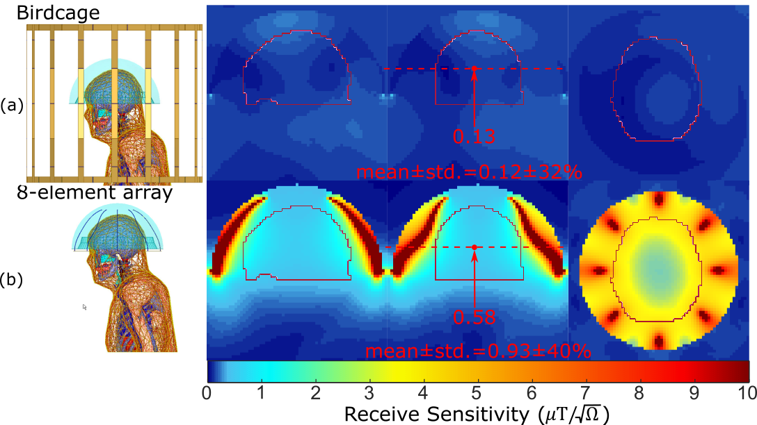
The simulated (Figure 2(c)) and measured (Figure 2(d)) input and mutual impedance are shown for adjacent dipole-loop elements, demonstrating elements are decoupled and tuned. The transmit fields of the BC are homogeneous (Figure 3(a)), but the MRgFUS helmet introduces distortion and banding with the simple hemisphere model (Figure 3(b)). In Figure 3(c), the receive array is observed to negligibly impact the mean transmit field efficiency (2% decrease) or homogeneity (0.3% lower CoV). This is validated by measurement results, where the mean flip angle without the array (Figure 3(d)) is the same as with the array (Figure 3(e)) and there is no visible distortion by the dipoles. Flip angles are only shown for pixels where SNR > 10. The CoV increases slightly (1.5%), which is likely due to the positioning. The banding profile due to the helmet distortion and CoV in the outlined regions of the head is similar in measurement and simulation. The 10g-averaged local SAR increases at the location where the hemisphere and head connect in the presence of the MRgFUS helmet (Figure 3(b)), compared to without (Figure 3(a)). There SAR increases slightly in the presence of the array (Figure 3(c)), but it is considered negligible compared to the uncertainty due to positioning and geometry. Within the most critical region outlined in Figure 5, the mean receive sensitivity of the BC (Figure5(a)) is 7.8-times lower than the receive array (Figure5(b)) and in the direct center the increase is 4.5-fold.Conclusion
The 8-element array will greatly improve image quality for MRgFUS, while its integration with the patient interface membrane and placement in the water will minimize impacts on the practical operation of the FUS or patient comfort. Future work will include experimental verification of SNR improvement and operation, acoustic characterization, testing and monitoring during MRgFUS.Acknowledgements
This work was supported by the Alberta Innovates postdoctoral fellowship in health innovation and the National Sciences and Engineering Research Council of Canada (NSERC) Discovery Grants program. We would like to acknowledge software access through CMC Microsystems, and support by the University of Alberta Faculty of Engineering IT. Technical support was provided by GE. The U of Calgary MR guided FUS program is supported by the Canadian Foundation for Innovation, the Cumming Medical Research Fund, and the Canadian Institutes for Health Research.References
1. Saniour I, Robb F, Taracila V, Voss HU, Kaplitt M, J. Chazen L, Winkler SA “Attenuation of the dark band artifact in MR-guided focused ultrasound using an ultra flexible high-sensitivity head coil” Proc. Intl. Soc. Mag. Reson. Med. (2021) 29:4010
2. Bitton RR, Sheingaouz E, Assif B, Kelm N, Dayan M, Pauly KB, Ghanouni P “Evaluation of an MRI receive head coil for use in transcranial MR guided focused ultrasound for functional neurosurgery” International Journal of Hyperthermia, (2021) 38(1):22-29
3. Stack C, Grafendorfer T, Robb F, Falk S, Inventors; General Electric Co, assignee. “Flexible radio frequency coil array with detachable straps for MRI” US patent US20190154775A1. 2019/05/23/, (2019).
4. Stormont RS, Lindsay SA, Taracila V, et al., Inventors; General Electric Co, assignee. “Systems for a radio frequency coil for MRI” US patentUS20190277926A1. 2019/09/12
5. Saniour I, Robb F, Taracila V, Vincent J, Voss HU, Kaplitt M, J. Chazen L, Winkler SA “Acoustically transparent and low-profile head coil for high precision magnetic resonance guided focused ultrasound at 3 T” Proc. Intl. Soc. Mag. Reson. Med. (2021) 29:4263
6. Yanamadala J, Noetscher GM, Rathi VK, Maliye S, Win HA, Tran AL, Jackson XJ, Htet AT, Kozlov M, Nazarian A, Louie S and Makarov SN "New VHP-Female v. 2.0 full-body computational phantom and its performance metrics using FEM simulator ANSYS HFSS," Conf. Proc. IEEE Eng. Med. Biol. Soc. (2015) 3237-3241
7. Sacolick LI, Wiesinger F, Hancu I, Vogel MW. B1 mapping by Bloch-Siegert shift. Magn Reson Med. 2010 May;63(5):1315-22. doi: 10.1002/mrm.22357. PMID: 20432302; PMCID: PMC2933656.
8. International Electrotechnical Commission. “Particular requirements for the basic safety and essential performance of magnetic resonance equipment for medical diagnosis” 3rd ed. Geneva, Switzerland: IEC 60601–2‐33; 2010.
9. Maunder, A, Rao, M, Robb, F, Wild, JM. “An 8-element Tx/Rx array utilizing MEMS detuning combined with 6 Rx loops for 19F and 1H lung imaging at 1.5T” Magn Reson Med. (2020) 84:2262– 2277
Figures