1085
A currentless remote decoupling circuit for receive-only endoscopic MRI coils using negative impedance converters1Université Paris-Saclay, BioMaps, Orsay, France, 2IHU L’Institut de RYthmologie et de Modélisation Cardiaque (LIRYC), Electrophysiology and Heart Modeling Institute, Fondation Bordeaux Université, 33600 Pessac, Bordeaux, France, 3Centre de recherche Cardio-Thoracique de Bordeaux, U1045, Université de Bordeaux, 33000, Bordeaux, France, 4INSERM, Centre de Recherche Cardio-Thoracique de Bordeaux, U1045, Université de Bordeaux, 33000, Bordeaux, France
Synopsis
Receive-only coils must be decoupled from the transmit coil during excitation. For conventional coils, decoupling is achieved using a resonant trap, which is switched during B1 transmit. However, in situations with very limited space like intravascular coils, this method remains problematic. We aimed to address efficient remote decoupling of a receive-only coil. We implemented an alternative approach by adding a “negative resistance” to the trap. This negative resistance is tailored in such a way that cancels out the positive resistance of the blocking trap, hence augmenting the quality factor of the trap and thus the decoupling efficiency.
Introduction
Receive-only MRI coils must be decoupled from the transmit coil during excitation. Otherwise, circulation of the induced current in the receive-only coil will cause an inhomogeneous B1 field and may also lead to tissue heating. For conventional coils surrounding the patients, these problems are usually overcome using a resonant blocking trap [1], which is switched during B1 transmit by passing a DC current through a (bulky) PIN diode. However, in situations like intravascular coils used for intra-cardiac imaging embedded on catheters, this classical method remains problematic since sending a DC current into patients’ body can lead to a cardiac arrest in the case of DC current leaks to the heart. Moreover, adding all required electronic components in a very limited space (catheter diameter are usually smaller than 2 mm) requires development of MR-compatible miniaturised elements that complicates the design of the MRI probe and increases the cost of such disposable single-use devices. Edelstein et al have proposed a mechanism for remote decoupling [1]. It has the advantage of avoiding PIN diodes and DC currents but may not provide efficient decoupling and, as a consequence, may result in images with B1 inhomogeneity artefacts.In this work, we aimed to address efficient remote decoupling of a receive-only coil. We tested the solution proposed in [1] and implemented a new approach by adding a “negative resistance” to the resonant blocking trap. This negative resistance is tailored in such a way that it is expected to cancel out the positive resistance of the blocking trap, hence augmenting the quality factor of the trap and thus the decoupling efficiency.
Methods
In order to test the ability of our negative resistance to improve the decoupling, a 2cm diameter receive-only surface coil was designed and implemented with three different decoupling circuits:First configuration: conventional active decoupling using a PIN diode. This is our reference method and provides a decoupling of ca 40 dB.
Second configuration: classic remote decoupling described in Fig. 1(b) that provides ca 20 dB of decoupling in our case.
Third configuration: an alternative method using a negative resistance for remote decoupling with a decoupling of ca 35 dB. For this, we use an operational amplifier in an especial configuration (Fig. 2) that looks like an adjustable negative resistance at about 64 MHz (corresponding to the precession frequency of 1H at 1.5 Tesla). This negative resistance is placed in series with the TR switch and reduces the total resistance of the blocking circuit. As a result, the quality factor of the blocking circuit and decoupling efficiency is expected to increase.
Decoupling measurements were performed using a homemade double probe and a vector network analyser (VNA). Each individual port of the double probe was connected to one port of the VNA and the parameter S12 was measured for each configuration.
Results
Two coils with classic active decoupling and conventional remote decoupling (configurations 1 and 2 in the “Method” section) were positioned on two perpendicular sides of a phantom. The integrated spine coil of the scanner (1.5T MRI scanner, Aera, Siemens Healthineers) was used as the receive coil. The obtained image as well as the decoupling efficiency of each coil are shown in Fig. 3, which implies that a minimum value of ca 35-40 dB is necessary to achieve artefact free images.Using an operational amplifier we fabricated a negative impedance converter circuit shown in Fig. 2. The capacitor C1 helps increasing the bandwidth of the circuit. The values of R1, R2 and C1 were determined empirically to achieve a nearly pure resistance of ca -3 Ohm after the impedance transforming cable. By adding our negative resistance in series with the TR switch, and by careful adjustment of its resistance we could achieve a decoupling of ca 35 dB. The S12 curves of our surface coil in non-decoupled and decoupled states are shown in Fig. 4 (a) and (b) respectively. A decoupling of 35 dB is comparable with the decoupling levels accessible with active decoupling method using DC currents (first configuration) which was shown sufficient to give an artefact free image.
Conclusion
In this work, we aimed to construct a remotely decoupled coil with improved decoupling to provide artefact free images. This is achieved by tailoring a negative resistance in such a way that it cancels out the resistance of the blocking trap, hence improving its quality factor and the decoupling level. We could achieve a decoupling of ca 35 dB (an improvement of ca 15 dB) which is expected to be sufficient to produce artefact free images. Further experiments (results not available at the moment of writing the abstract) are required to validate the proposed method. If successful, this method will allow for the development of safe (no active components inserted into the body requiring DC current), simplified circuit (only matching and tuning capacitors at the coil’s position) and cost-effective (no need for miniaturised MR-compatible components, no specific constraint on cable length as in the second configuration) intra-cardiac coil.Acknowledgements
This work was supported by French National Research Agency, projects CARCOI (ANR-19-CE19-0008-02) and IHU-LIRYC (ANR-10-IAHU04-LIRYC).References
- W. A. Edelstein, C. J. Hardy, and O. M. Mueller, ‘Electronic decoupling of surface-coil receivers for NMR imaging and spectroscopy’, Journal of Magnetic Resonance, vol. 67, no.1, pp. 156–161, Mar.1986. M.
- Delcey, P. Bour, I. Saniour, D. El Hamrani, V. Ozenne, M. Poirier-Quinot, and B. Quesson, ‘Feasibility of motion-resolved high resolution cardiac MRI using a local receiver and MR-tracking micro-coils’ ISMRM 2021.
Figures
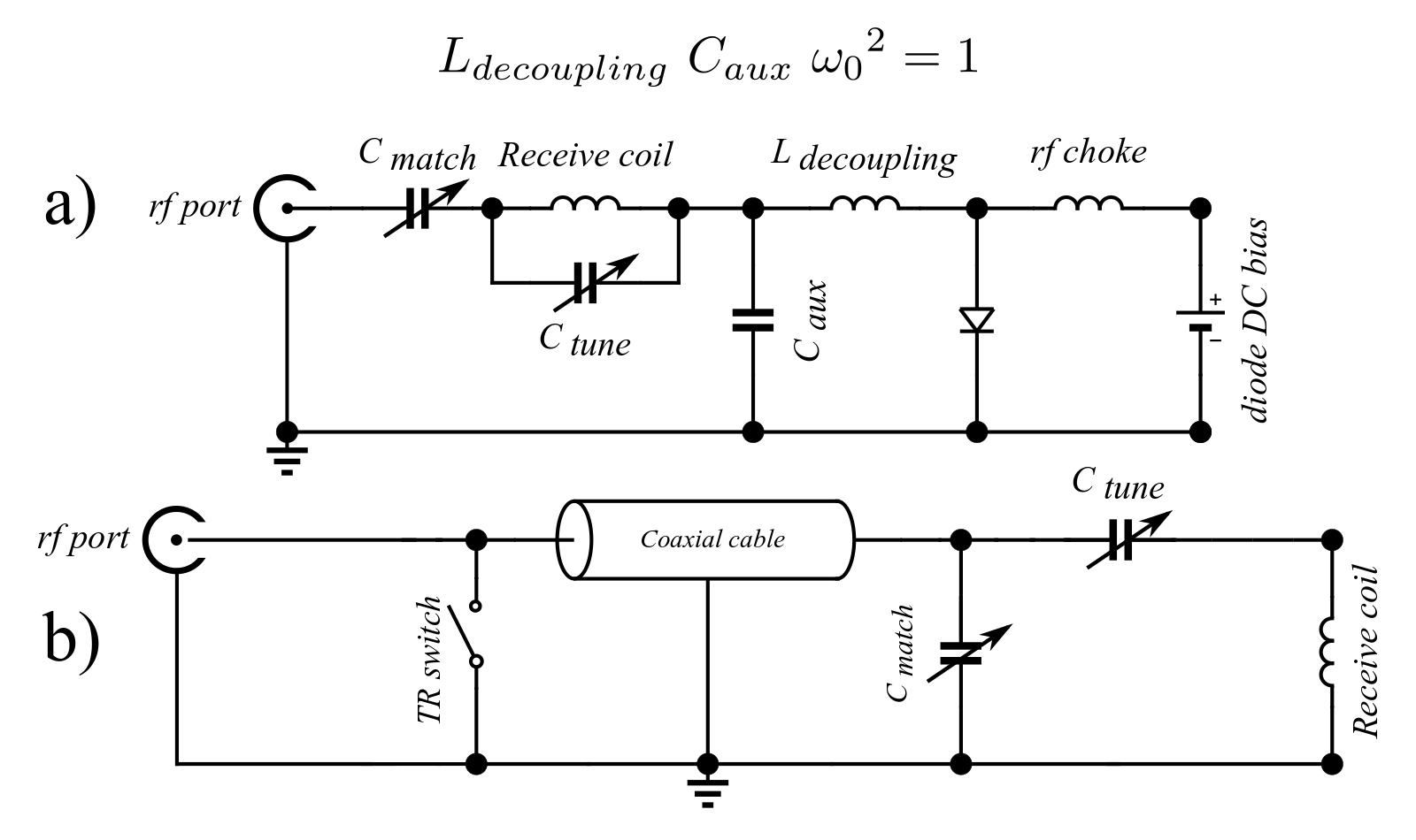
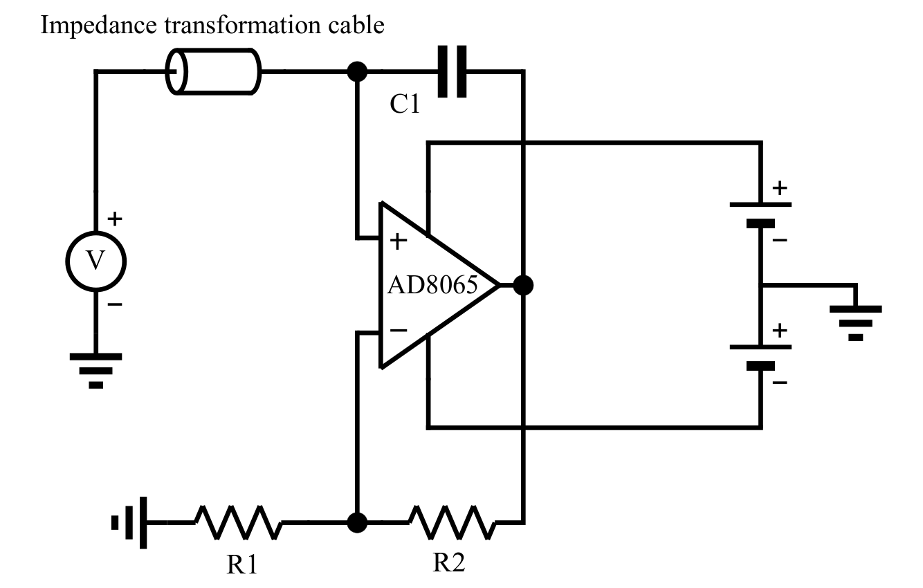
Fig. 2: Fabricated negative impedance converter. The capacitor C1 helps increasing the effective bandwidth of the circuit. If all components are ideal such a circuit produces a negative capacitance, and looks purely reactive. In our case however, it leads to an impedance with non-zero resistive and reactive parts. The values of R1, R2 and C1 were determined empirically to achieve a nearly pure resistance of ca -3 Ohm after the impedance transforming cable.
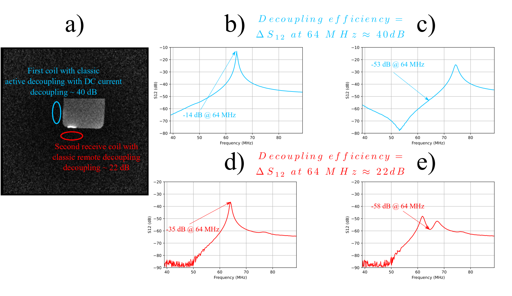
Fig. 3: (a) Two surface coils with classical active decoupling and classical remote decoupling were positioned perpendicularly close to a phantom, as shown in the image. (b) and (c) S12 curves of the double-probe used to measure the decoupling level of the coil in the first configuration represented in blue in non-decoupled and decoupled states respectively. (d) and (e) S12 curves of the double-probe used to measure the decoupling level of the coil in the second configuration represented in red in non-decoupled and decoupled states respectively.
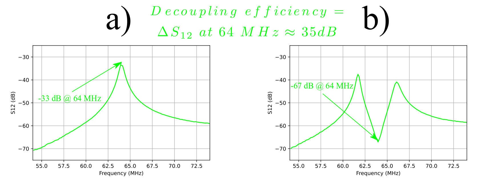
Fig. 4: S12 curves of the double-probe used to measure the decoupling level. (a) Non-decoupled state and (b) decoupled using our negative impedance converter circuit.