0990
External Dynamic InTerference Estimation and Removal (EDITER) for low field MRI
Sai Abitha Srinivas1,2, Stephen F Cauley3,4, Jason P Stockmann3,4, Charlotte R Sappo1,2, Christopher E Vaughn1,2, Lawrence Wald3,4,5, William Grissom1,2,6,7, and Clarissa Cooley3,4
1Vanderbilt University Institute of Imaging Science, Nashville, TN, United States, 2Department of Biomedical Engineering, Vanderbilt University, Nashville, TN, United States, 3Harvard Medical School, Boston, MA, United States, 4Dept. of Radiology, Massachusetts General Hospital, Athinoula A Martinos Center for Biomedical Imaging, Boston, MA, United States, 5Harvard-MIT Division of Health Sciences and Technology, Cambridge, MA, United States, 6Department of Electrical Engineering, Vanderbilt University, Nashville, TN, United States, 7Department of Radiology, Vanderbilt University, Nashville, TN, United States
1Vanderbilt University Institute of Imaging Science, Nashville, TN, United States, 2Department of Biomedical Engineering, Vanderbilt University, Nashville, TN, United States, 3Harvard Medical School, Boston, MA, United States, 4Dept. of Radiology, Massachusetts General Hospital, Athinoula A Martinos Center for Biomedical Imaging, Boston, MA, United States, 5Harvard-MIT Division of Health Sciences and Technology, Cambridge, MA, United States, 6Department of Electrical Engineering, Vanderbilt University, Nashville, TN, United States, 7Department of Radiology, Vanderbilt University, Nashville, TN, United States
Synopsis
Point of care MRI requires operation outside of an MR shielded room where electromagnetic interference can degrade image quality. To address this, we demonstrate a self-calibrated generalized dynamic model to retrospectively remove time-varying external interference. The method uses data acquired from multiple Electromagnetic Interference (EMI) detectors simultaneous with the primary MR coil. We test the approach both in a controlled EMI setting on an 80mT Halbach scanner and an uncontrolled real-world EMI setting on a 47.5mT permanent magnet open MRI system.
Introduction
Electromagnetic Interference (EMI) contaminates MR signals & decreases the diagnostic quality of MR images. Conventional MRI scanners use Faraday shields to eliminate EMI. However, the necessity of an RF shielded room precludes MR’s use in a point-of-care setting, & alternative approaches to EMI suppression are needed. The use of external detectors (pick up coils) for image noise reduction in MRI has been described using separately acquired calibration data to calculate a transfer function [1,2,3], but this requires increased scan time & can fail to suppress intermittent or time-varying EMI. To address this, we propose to suppress EMI using only sensor data that is acquired simultaneously with the imaging data. This has the advantage of not requiring modifications to the imaging sequence or increased scan time, while enabling removal of time-varying EMI.Theory
EDITER assumes that the signal received by the primary receive coil, $$$s(k_x,k_y)$$$, is the sum of the unwanted EMI $$$e' (k_x,k_y)$$$, & the desired EMI-free k-space signal $$$s' (k_x,k_y)$$$:$$s(k_x,k_y )=e' (k_x,k_y )+s' (k_x,k_y )$$
To remove the EMI $$$e' (k_x,k_y)$$$, we assume that data is available from Nc external detectors $$$e_i (k_x,k_y ),i=1,…,N_c$$$. A convolution model along the readout ($$$k_x$$$) & phase encoding ($$$k_y$$$) directions relates the EMI observed by the primary imaging coil to that observed by the detectors:
$$e'(k_x,k_y )=\sum_{i=1}^{N_c} e_i (k_x,k_y)*h_i (k_x,k_y )$$
Each impulse response function is assumed to have limited spectral support, i.e., $$$h_i (k_x,k_y )=0,|k_x |>\Delta k_x or |k_y |> \Delta k_y$$$. In the most restrictive case, $$$\Delta k_x =1 , \Delta k_y =1$$$, (eq. 2) represents a scalar combination of the detector coils:
$$e'(k_x,k_y )=\sum_{i=1}^{N_c} e_i (k_x,k_y )∙h_i$$
An illustration of fitting impulse response functions is shown in Figure 1. In the case of temporally static EMI, a single set of impulse response functions would be valid across the full extent of k-space & all available data could be used during the fit. The least squares solution $$$\overrightarrow h=E^† \overrightarrow s$$$ is used to fit the model & the EMI can be removed from the primary coil data as: $$$\overrightarrow s'≈\overrightarrow s-E\overrightarrow h$$$. In case of temporally varying EMI, we fit different impulse response functions for successive temporal windows (e.g., one or more successively acquired echoes or phase encode lines).
Methods
A portable, head-only low-field MRI scanner [4] was used to demonstrate EDITER in controlled EMI settings using the setup shown in Figure 2A [5,6]. Five identical tuned (3.38 MHz) EMI detectors were built from 10-turn coils as shown in Figure 2B & placed as illustrated in Figure 2C. The scanner was placed in a shielded room with four different controlled EMI sources while imaging a 3D-printed brain slice phantom. For in-vivo imaging, one healthy subject (S1: male, 24 y/o) was scanned in a shielded room with a frequency generator (FG) EMI source, with IRB approval.An open 47.5mT permanent magnet MRI scanner [7] was used to demonstrate EDITER in real-world EMI settings as this scanner is not sited in an RF shield room & is subject to uncontrolled EMI at Vanderbilt University Medical Center. Images were acquired in-vivo (S1: male, 25 y/o) using a single channel Tx/Rx RF coil [5,6] with IRB approval & with 2 different passive shielding configurations within the magnet, illustrated in Figures 2D & 2E. For in vivo studies, we used an electrode as an EMI detector to directly measure the EMI that is coupled through the patient [8, 9]. This was attached to the patient’s wrist to measure EMI & served as 1 of 2 of the EMI detectors. The second EMI detector was a pick-up coil tuned to Larmor frequency.
A 3D multi-echo Rapid Acquisition & Relaxation Enhancement (RARE) volumetric spin echo sequence [4, 10] shown in Figure 3 was used to obtain the data shown in Figure 4 & 5 for both the controlled & uncontrolled EMI settings. Image quality improvements were measured as RMSE of the image space residual compared to ground truth & the EMI removal percentage using the standard deviation in a region outside the object in the corrected & uncorrected images.
Results
Controlled EMI settings: Figure 4A shows that EDITER reduced image RMSE by 89.2% (frequency generator), 95.7% (stepper motor), 74.7% (broadband), & 93.3% (broadband + stepper motor), & removed 96.6%, 97.3%, 76.2%, & 86.8% of EMI, respectively. The dynamic correction resulted in an RMSE improvement of 93.3% & an EMI removal percentage of 86.8%, compared to 73.7% & 70.4% with the static correction. Figure 4B shows that in vivo, the RMSE between the corrected image & ground truth averaged across partitions was 1.57, showing a 91.3% RMSE reduction, & 91.3% of the EMI was removed.Uncontrolled EMI settings: Figure 5 shows that in-vivo, the pickup coil removed 37.2% & 23.2% of the EMI, the electrode removed 89.9% & 64.6% of EMI, & the combination removed 90.2% & 99.9% of EMI in the “open” & “flexible shielding” configuration, respectively.
Discussion
EDITER is a self-calibrated EMI suppression method that is agnostic to k-space sampling pattern & requires no additional data acquisition windows in a pulse sequence. It was validated in two low-field MRI systems at different centers using pick-up coils & electrodes as EMI detectors. Applying the algorithm improved image quality in scenarios where EMI is robust & time-varying, thus allowing the operation of portable scanners in EMI-unfriendly environments without a traditional Faraday shielded room.Acknowledgements
Funding source R01EB018976, 5T32EB1680 and R01EB030414.References
- Rearick Todd et al., “Noise Suppression methods and apparatus”. Patent no. WO2016037028. 2017.
- Patz.S, Hrovat.M & Butler. P.J. “Systems and methods for portable magnetic resonance measurements of lung properties”. Patent no. WO2013016639A1. 2013.
- Srinivas, S. A., Cooley, C. Z., Stockmann, J. P., McDaniel, P. C. & Wald, L. L. Retrospective Electromagnetic Interference Mitigation in a Portable Low Field MRI System. Proc. 28th Annu. Meet. ISMRM. 2020 (2020).
- Cooley, C.Z., McDaniel, P.C., Stockmann, J.P. et al. A portable scanner for magnetic resonance imaging of the brain. Nat Biomed Eng (2020). https://doi.org/10.1038/s41551-020-00641-5
- C. LaPierre, M. Sarracanie, D. E. J. Waddington, M. S. Rosen, and L. L. Wald, “A single channel spiral volume coil for in vivo imaging of the whole human brain at 6.5 mT,” Proc. 23rd Annu. Meet. ISMRM, Toronto, 2015, p. 1793, 2015
- Sarracanie M, LaPierre CD, Salameh N, Waddington DEJ, Witzel T and Rosen MS. Low-cost high-performance MRI. Sci Rep. 2015. doi: 10.1038/srep15177
- Coffey AM, Feldman MA, Shchepin RV. et.al. High-resolution hyperpolarized in vivo metabolic 13C spectroscopy at low magnetic field (48.7 mT) following murine tail-vein injection. J Magn Reson. 2017. doi: 10.1016/j.jmr.2017.06.009.
- Ren A, Du Z, Li J, Hu F, Yang X and Abbas H. Adaptive Interference Cancellation of ECG Signals. Sensors. 2017. doi: 10.3390/s17050942.
- Darroudi A, Parchami J, Razavi MK, and Sarbisheie G. EEG adaptive noise cancellation using information theoretic approach. Biomed Mater Eng. 2017. doi: 10.3233/BME-171680.
- Hennig J, Nauerth A, and Friedburg H. RARE imaging: a fast imaging method for clinical MR. Magn Reson Med. 1986. doi: 10.1002/mrm.1910030602.
Figures
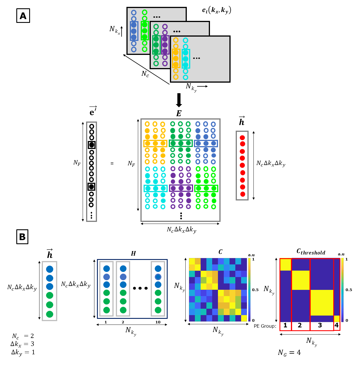
Figure 1: EDITER
EMI estimation overview. A) Fitting
Impulse Responses. Top: The k-space data of the external EMI detectors is
acquired simultaneously with the imaging data from all the EMI detectors.
Bottom: The EMI present in the primary image is estimated with
the impulse response function and the EMI convolution matrix (E). The impulse response
is obtained using the inverse of the E matrix and the primary MR coil data. B) Dynamic Phase Encode Binning method using separate impulse
response function for each temporal group of PE lines individually by
thresholding.
Figure
2: Experimental setup for portable 80mT scanner. (A) The single channel
primary MR spiral volume Tx/Rx coil. B) Five external EMI detector coils tuned
to the Larmor frequency to mimic the frequency response of the primary MR coil.
C) Placement of the EMI detector coils. Experimental setup for open 47.5mT
scanner. Experiments were performed
in 2 shielding configurations. C) The open shielding included a copper box
surrounding the head open on one side. D) The flexible shielding included the
addition of copper mesh, grounded to the copper box and draped over the
subject.
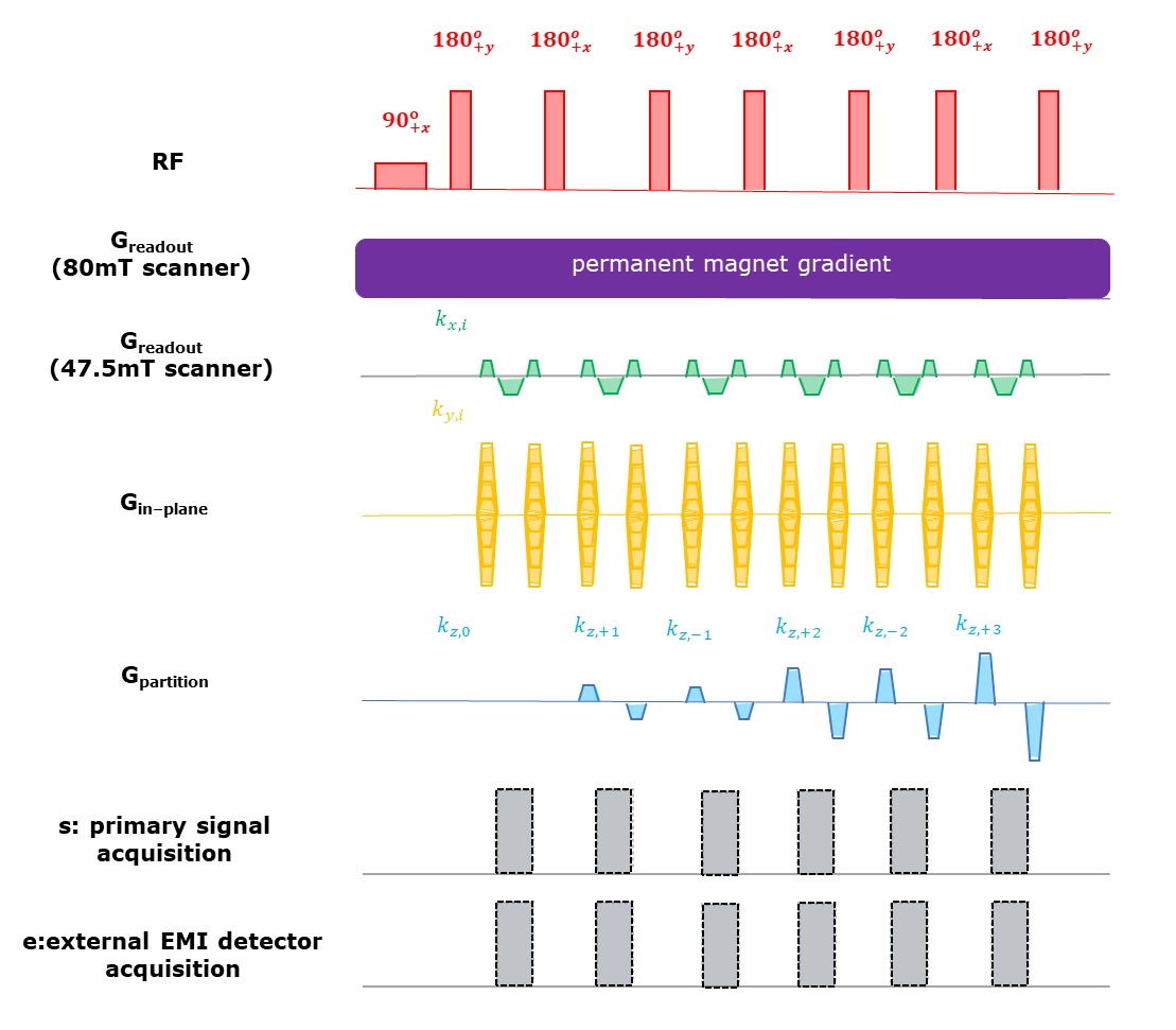
Figure
3: 3D
RARE pulse sequence for EDITER. The Greadout gradient was the
built-in permanent magnet encoding field for the portable 80mT scanner. A
conventional pulsed readout gradient as shown in the 4th row was played out
in the 47.5mT open scanner. The Gin-phase & Gpartition
phase encoding blips were applied using dedicated gradient coils for both
systems. The signal acquisition alternated between the narrow “FID echoes” & wider “spectral echoes” in the portable 80mT scanner. Only “FID echoes” were
generated in the 47.5mT low field scanner using hard pulse excitation & refocusing.
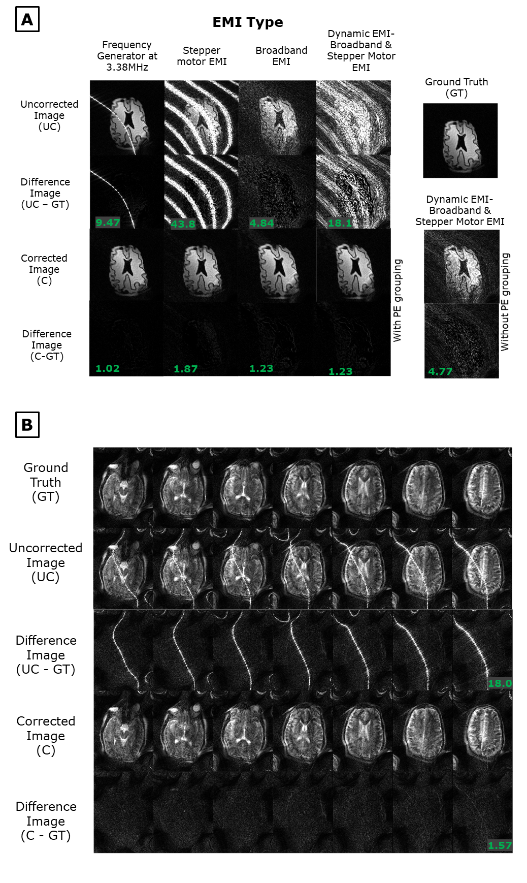
Figure 4: Experiments on the portable 80mT scanner A) 2D images of a brain slice phantom
with the following EMI. 1) single band EMI from a function generator
(FG). 2) Narrowband EMI from a stepper motor (SM). 3) broadband EMI (BB). 4)
Dynamic switching between the SM and BB sources. For the dynamic EMI source, EDITER
correction with & without dynamic PE grouping is shown. B) in vivo
T2 weighted 3D images of subject 1 (male, 24 y/o) were acquired with the
frequency generator EMI source. Correction was performed with a single pickup
coil. The average RMSE of the difference images is shown for A & B.
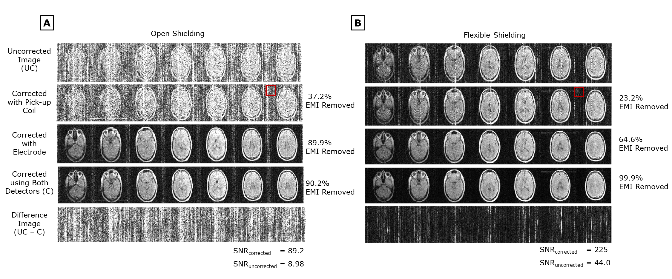
Figure
5: in-vivo
PD weighted images of Subject 1 (male, 25 y/o) in the 47.5mT scanner’s A)
open shielding configuration setup and B) flexible shielding
configuration setup. EDITER correction is shown using each EMI detector
individually and together. Percent EMI removed by the EDITER method using Eq.1 is
indicated on the right. The red box indicates the region outside the object
that was used for this measurement. SNR for both the uncorrected and corrected
images are shown.
DOI: https://doi.org/10.58530/2022/0003