0957
Imaging near metal at 0.55 T using gradient-echo based sequences: Feasibility and Opportunities1Electrical and Computer Engineering, University of Southern California, Los Angeles, CA, United States, 2Radiology, Stanford University, Stanford, CA, United States, 3Electrical Engineering, Stanford University, Stanford, CA, United States, 4Bioengineering, Stanford University, Stanford, CA, United States, 5Biomedical Engineering, University of Southern California, Los Angeles, CA, United States
Synopsis
The large magnetic susceptibility difference between metallic implants and surrounding tissues causes severe MRI artifacts that scale with the B0 field strength. At conventional field strengths, spin-echo based multispectral imaging is used to mitigate this artifact and produce diagnostic images. At lower field strengths, such as 0.55 T, other strategies may be feasible. Here, we investigate gradient-echo based sequences for imaging near metal at 0.55 T, which provide high SNR efficiency and different contrast.
Introduction
MRI near metallic implants suffers from artifacts induced by magnetic susceptibility. These appear as distortions and signal losses1. Artifact severity scales with the field inhomogeneity, which is related to the specific metal composition and, importantly, the B0 field strength. At conventional field strengths (1.5T and 3T), spin-echo-based sequences are widely used as dephased spins are refocused at the spin-echo. New lower field strengths systems with high-performance gradients2 provide the opportunity to explore other imaging strategies due to the reduced field inhomogeneity3,4,5,6. Here, we explore the feasibility and opportunities for MRI near metal at 0.55T using rapid gradient-echo-based sequences7. Specifically, we investigate the balanced steady-state free precession (bSSFP) sequence and its dephased variants.bSSFP is a fast-imaging sequence with high SNR and unique contrast, but it produces banding artifacts due to its sensitivity to off-resonance8. Banding artifacts are extreme adjacent to metal due to large variations in field inhomogeneity and can be corrected with multiple phase-cycled bSSFP acquisitions9. Banding artifacts can also be mitigated via a dephasing gradient added along x, y, or z directions that effectively averages the bSSFP spectral profile in each voxel10,11,12. Dephased bSSFP sequences retain comparable contrast but with lower SNR. Here we specifically investigate the performance of bSSFP with different dephasing while imaging near metal at 0.55T.
Methods
Experiments were performed using a whole-body 0.55T system (prototype MAGNETOM Aera, Siemens Healthineers, Erlangen, Germany) equipped with high-performance shielded gradients (45 mT/m amplitude, 200 T/m/s slew rate). Imaging was performed using the RTHawk real-time system (HeartVista Inc., Menlo Park, CA).2D bSSFP and its variants with different amounts of dephasing were implemented in RTHawk. Scan parameters for custom-implemented sequences and vendor-provided sequences (2D bSSFP, 3D bSSFP, GRE, SPGR, TSE with VAT, and SEMAC) are described in Table 1.
Banding artifact mitigation performance of dephased bSSFP was evaluated, and contrasts of the custom-implemented sequences were compared by using the MnCl2 array of the ISMRM/NIST phantom13. Shim was intentionally distorted to create an inhomogeneous field where banding artifacts are visible. Effects of the amount of extra dephasing (π/2,π,3π/2,2π,4π,6π,8π per pixel) applied to bSSFP were demonstrated by using the ISMRM/NIST phantom. Data were collected using a 16-channel head/neck receive coil.
Effects of the amount of extra dephasing were also demonstrated by using a hip implant phantom with a ceramic head and titanium stem placed into a container filled with water. Performance of the custom-implemented sequences and the vendor-provided sequences were evaluated by using the hip implant phantom. Data were collected using a 6-channel body array.
Results
Figure 1 demonstrates the effect of the amount of extra dephasing on the ISMRM/NIST phantom and the hip implant phantom. Banding artifacts can be eliminated by dephased bSSFP, with a reduction in SNR. High-frequency signal variations are observed in the images with lower amounts of dephasing (π/2 and π) while bands collapse to within a few pixels. Residual ripples are still visible in various places of the 3π/2 dephased images (blue arrows). Most of the banding artifacts are eliminated with 2π dephasing, although some minor banding artifacts near metal remain (yellow arrow) where dephasing is partly canceled by background gradients. Banding artifacts are no longer visible when bands fully collapse into a voxel with higher amounts of dephasing. However, the signal intensity decreases with increased dephasing, likely due to diffusion effects.Figure 2 shows the contrast comparisons of bSSFP, dephased bSSFP by 2π/pixel along x, and by 4π/pixel along x and z. Vial numbers of the MnCl2 array of the ISMRM/NIST phantom are shown on top of the bSSFP image. Contrasts and normalized contrasts of three sequences are plotted for each vial. Although the dephased bSSFP sequences have lower (79%) signal intensities than bSSFP, they retain bSSFP-like contrast.
Figures 3 and 4 compare several gradient-echo and spin-echo-based sequences along with their scan times for coronal and sagittal slices of the hip implant phantom, respectively. Gradient-echo-based sequences can provide sharp images with little artifact and high imaging speed for this implant configuration at 0.55T.
Discussion
There are potential benefits of using gradient-echo sequences for metal imaging, such as the potential for extremely short scan times (2-3 seconds) and the potential for sharper images via 3D imaging in absence of echo-train decay. Both require dedicated exploration, and tailoring to specific applications.Performance varies greatly with implant material. CoCr implants were tested, which typically require SEMAC imaging with a factor≥10 at 0.55T (not shown). Such implant materials with a higher magnetic susceptibility pose greater challenges for gradient-echo-based imaging because the signal very close to the implant can be lost due to high intravoxel signal dephasing. Given the increased prevalence of titanium implants, there may be value in developing methods optimized for this material.
All work was done with custom-implemented dephased bSSFP. Our implementation had TR=9.25 ms, whereas the vendor-provided bSSFP sequence with the same imaging parameters had TR=4.42 ms. The shorter TR would improve the signal loss around the implant, as can be seen in Figures 3&4 (green arrows).
Conclusion
We demonstrate the feasibility of gradient-echo-based sequences for imaging near metal at 0.55T in phantoms. We show bSSFP-like contrast with ultra-short imaging times (~3 secs per slice) and without banding artifacts.Acknowledgements
We acknowledge grant support from the National Science Foundation (#1828736) and research support from Siemens Healthineers.References
1. Koch K, Hargreaves B, Pauly K, et al. Magnetic resonance imaging near metal implants. Journal of Magnetic Resonance Imaging 2010;32:773-787.
2. Campbell-Washburn AE, Ramasawmy R, Restivo MC, et al. Opportunities in Interventional and Diagnostic Imaging by Using High-Performance Low-Field-Strength MRI. Radiology 2019;293:384-393.
3. Bandettini WP, Mancini C, Shanbhag S, et al. A Comparison of Metal Artifacts in Cardiovascular MRI at 0.55T and 1.5T. Proc. ISMRM 29th Scientific Session, Online, May 2021. p3636.
4. Harris CT, Curtis AT, Connell IRO, et al. 2D Imaging near Metallic Implants at 0.5T using High Time-Bandwidth Product RF pulses. Proc. ISMRM 27th Scientific Session, Montreal, May 2019. p4605.
5. Basar B, Sonmez M, Yildirim D, et al. Susceptibility artifacts from metallic markers and cardiac catheterization devices on a high-performance 0.55 T MRI system. Magnetic Resonance Imaging 2021;77:14-20.
6. Khodarahmi I, Brinkmann IM, Lin D, et al. Advanced Low-Field MRI of Hip Arthroplasty Implants: First Experience at 0.55 T. Proc. ISMRM 29th Scientific Session, Online, May 2021. p0521.
7. Hargreaves B. Rapid gradient‐echo imaging. Journal of Magnetic Resonance Imaging 2012;36:1300-1313.
8. Scheffler K, Lehnhardt S. Principles and applications of balanced SSFP techniques. European Radiology 2003;13:2409-2418.
9. Xiang Q, Hoff M. Banding artifact removal for bSSFP imaging with an elliptical signal model. Magnetic Resonance in Medicine 2014;71:927-933.
10. Martin T, Wang Y, Rashid S, et al. Highly Accelerated SSFP Imaging with Controlled Aliasing in Parallel Imaging and integrated-SSFP (CAIPI-iSSFP). Investigative Magnetic Resonance Imaging 2017;21:210.
11. Sun K, Xue R, Zhang P, et al. Integrated SSFP for functional brain mapping at 7 T with reduced susceptibility artifact. Journal of Magnetic Resonance 2017;276:22-30.
12. Mikaiel S, Martin T, Zhong X, et al. Real-Time Golden Angle Radial iSSFP: Impact of the Gradient Spoiler Direction on Motion and Flow Effects. Proc. ISMRM 26th Scientific Session, Paris, June 2018. p4162.
13. Stupic KF, Ainslie M, Boss MA, et al. A standard system phantom for magnetic resonance imaging. Magn. Reson. Med. 2021;86:1194–1211.
Figures
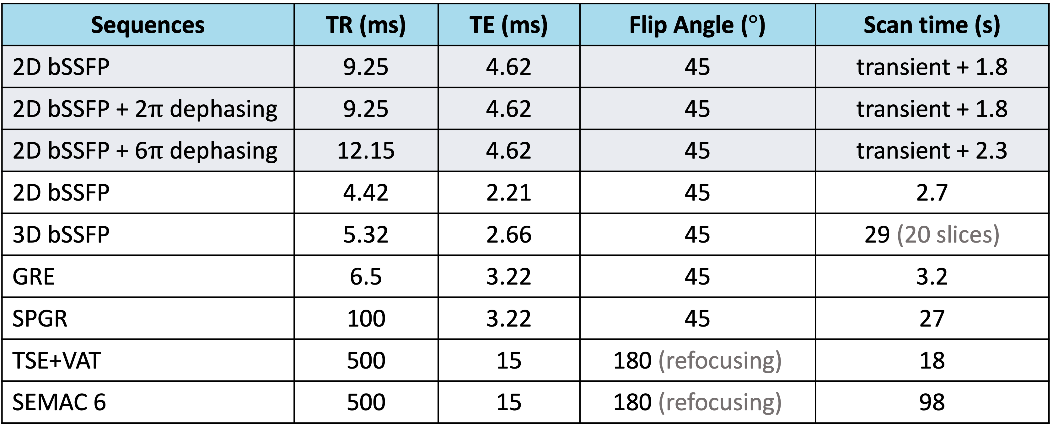
Table 1. Scan parameters (TR, TE, flip angle and scan time) for custom-implemented sequences (gray rows) and vendor-provided sequences.
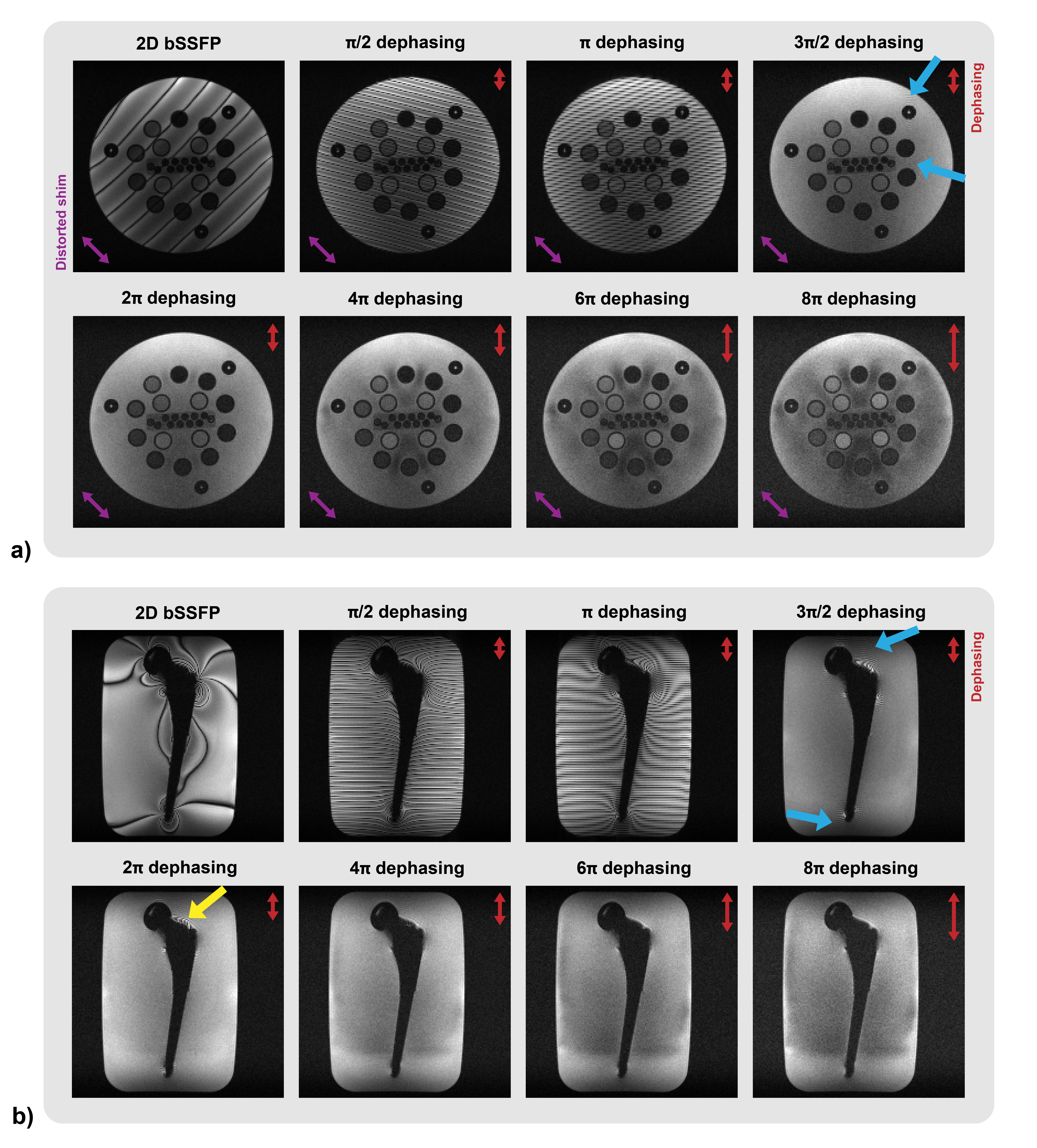
Figure 1. Demonstration of the impact of dephasing (π/2, π, 3π/2, 2π, 4π, 6π, 8π per pixel) applied in the up/down direction (red arrows) on bSSFP image quality in (a) the ISMRM/NIST phantom and (b) a hip implant phantom with a ceramic head and titanium stem. The shim is distorted for the NIST phantom experiments to achieve an inhomogeneous B0 field (purple arrows). Blue arrows point to the residual ripples due to non-integer dephasing, while the yellow arrow indicates the region where minor banding persists as the background gradient is partially canceling the dephasing gradient.
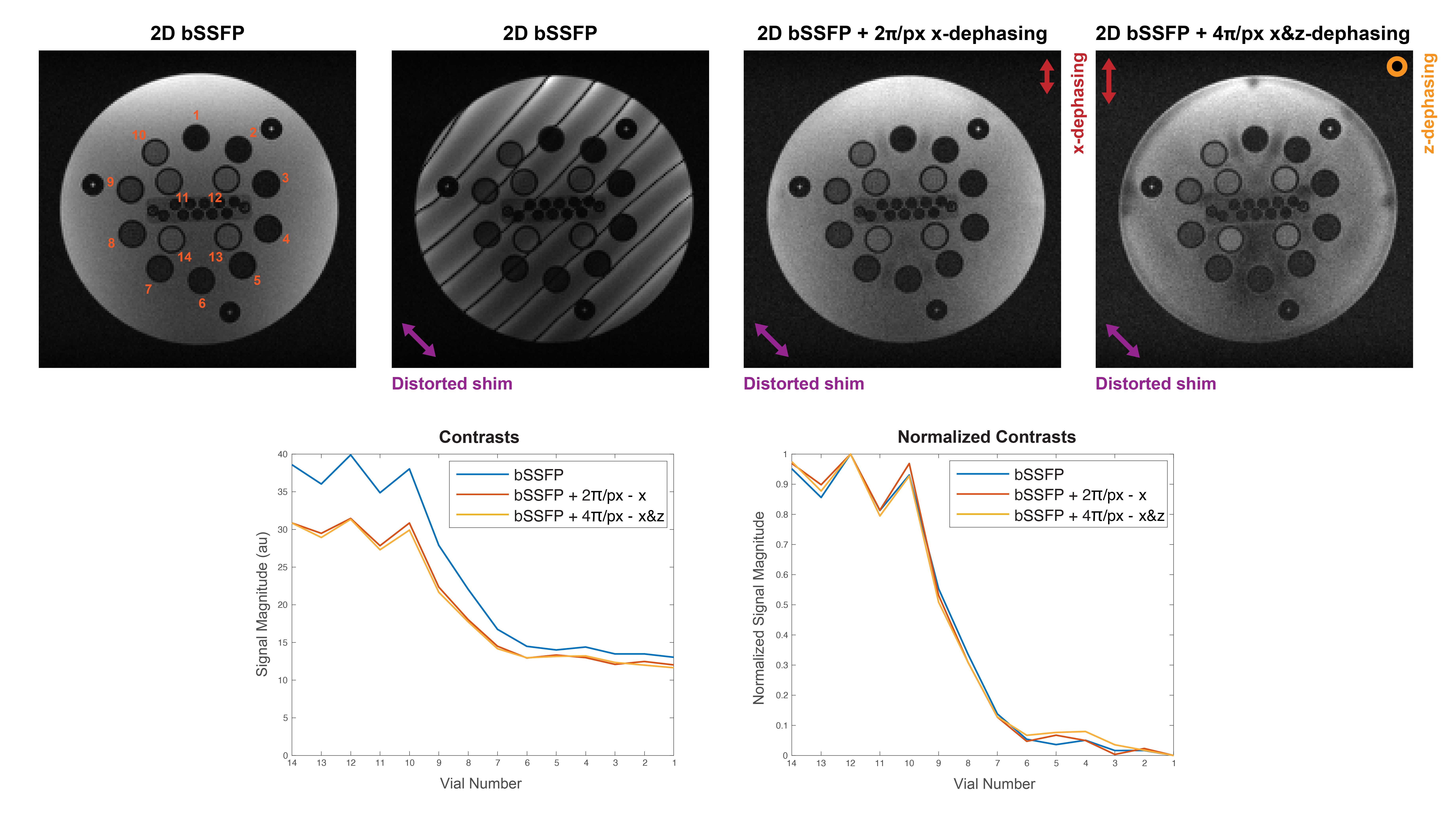
Figure 2. Contrast comparison of bSSFP, dephased bSSFP by 2π/pixel along x, and by 4π/pixel along x and z. Directions of the dephasing gradients are shown with red arrows and an orange circle. An extra linear shim is applied to achieve an inhomogeneous B0 field (purple arrows). bSSFP images obtained before and after the distorted shim are given. Vial numbers are shown on top of the leftmost bSSFP image. Contrasts and normalized contrasts of three sequences are plotted for each vial. Although dephased bSSFP reduces signal intensity compared to bSSFP, images retain bSSFP-like contrast.
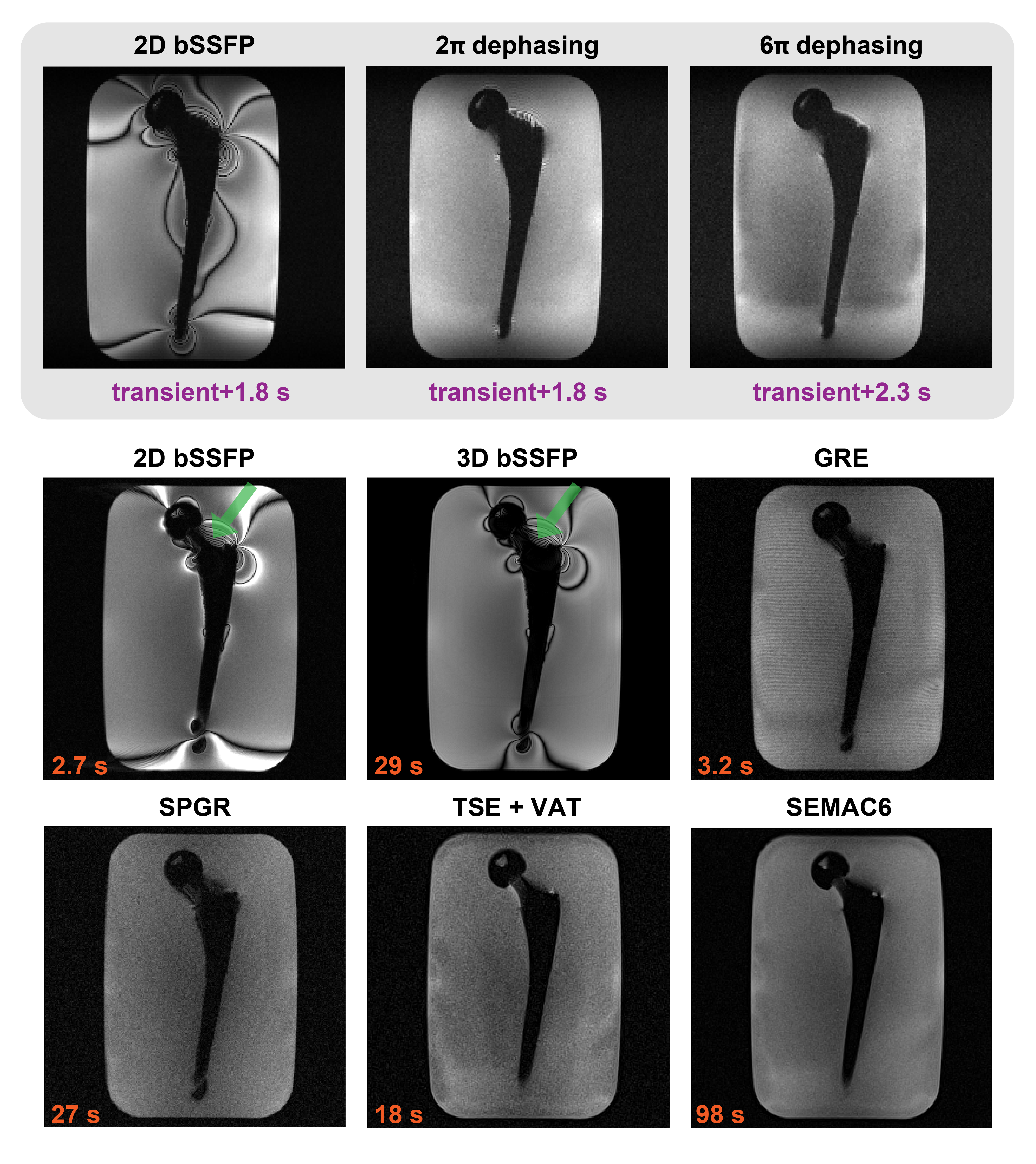
Figure 3. Comparisons of several gradient-echo-based and spin-echo-based sequences along with their scan times by using a coronal slice of a hip implant phantom with a ceramic head and titanium stem. Images from the custom-implemented sequences are shown inside a gray box. The outline of the implant neck looks clearer (green arrows) in the vendor-provided bSSFP sequences as TR and TE of the custom-implemented bSSFP sequences are not optimized. Gradient echo-based sequences can provide sharp images with little artifact and high imaging speed for this implant configuration at 0.55T.
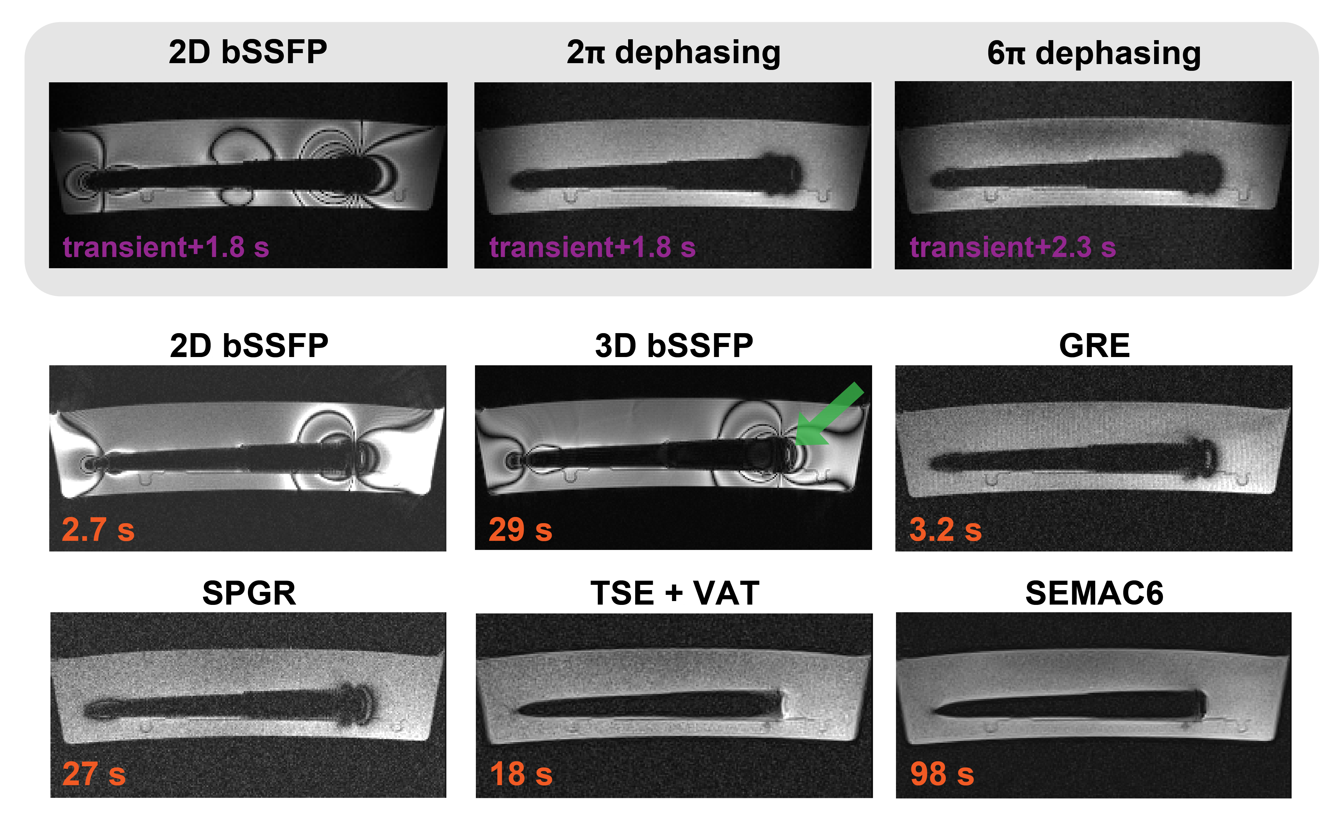
Figure 4. Comparisons of several gradient-echo-based and spin-echo-based sequences along with their scan times by using a sagittal slice of a hip implant phantom with a ceramic head and titanium stem. Images from the custom-implemented sequences are shown inside a gray box. The top part of the implant stem looks clearer (green arrow) in the vendor-provided bSSFP sequences as TR and TE of the custom-implemented bSSFP sequences are not optimized. Therefore, some of the signal loss around the top of the stem shown in the custom-implemented results can be further recovered if optimized.