0855
Real time visual feedback for reproducible head motion
Adam van Niekerk1, Johan Berglund2, Henric Ryden1,3, Tim Sprenger1,4, Ola Norbeck1,3, Enrico Avventi1,3, and Stefan Skare1,3
1Clinical Neuroscience, Karolinska Institutet, Stockholm, Sweden, 2Medical Physics, Uppsala University Hospital, Uppsala, Sweden, 3Neuroradiology, Karolinska University Hospital, Stockholm, Sweden, 4MR Applied Science Laboratory Europe, GE healthcare, Stockholm, Sweden
1Clinical Neuroscience, Karolinska Institutet, Stockholm, Sweden, 2Medical Physics, Uppsala University Hospital, Uppsala, Sweden, 3Neuroradiology, Karolinska University Hospital, Stockholm, Sweden, 4MR Applied Science Laboratory Europe, GE healthcare, Stockholm, Sweden
Synopsis
The timing and magnitude of volunteer head motion has a significant impact on artefact level. It can therefore be difficult to reproduce motion correction results. Moreover, it is of interest to replicate patient motion retrospectively, in volunteers, to better understand the efficacy of a motion correction method. We attempt to solve this by stamping motion updates with a synchronisation “tag”. A rolling model is used to project the volunteer’s pose onto an MRI compatible display. The “tag” synchronised pose from a previous scan is then shown alongside the volunteer’s current pose, allowing them to track and hence reproduce the motion.
Introduction
When presenting a new motion correction (MOCO) method results are regularly validated through volunteer experiments in which a predetermined set of movements are repeated. A major drawback of this is that the prevalence of artefacts is strongly dependent on the type of pulse sequence, in what order k-space is filled, and how this is correlated to when and how the volunteer moved. Reproducing results between different subjects can therefore be challenging. This makes comparisons for different subjects, different setups or even different implementations of the same setup difficult.Furthermore, when translating a method to real patients it may be impractical to make these image comparisons. We therefore identified a need for accurately repeating artificial or even real patient motion patterns in volunteer experiments to gain better insight into the efficacy of MOCO methods.
To this end, we developed a motion visualisation tool that can be used to playback a motion parameter log file to a volunteer. The playback is synchronised with the pulse sequence execution by storing a frame number that links each update to an encoding step of the pulse sequence. The volunteer's head pose is constantly recorded using a tracking device. The “playback” pose from the desired motion pattern can then be displayed alongside the volunteer’s current pose, allowing them to adjust their head so that they reproduce the motion stored in the log file.
Methods
The modifications to the scanner setup are shown in (green) Figure 1. A laptop, running the visualisation tool, was connected to:- the realtime computer of the scanner (to synchronise the intended motion pattern with the sequence playout),
- a motion tracker (to obtain realtime feedback of the volunteers head position) and
- an MRI compatible monitor (for displaying the information to the volunteer).
The visualisation tool was written in Julia programming language1 and made use of the Makie2 package for real time data visualisation. The display included scatter plots of the current motion on the left of the screen. The centre showed the “target” and “current” markers and the right section displayed a 3D model of a head transformed by the current pose. An example data snippet is animated in Figure 2.
A Wireless Radiofrequency-triggered Acquisition Device (WRAD)3 was used to capture the volunteer motion for the visualisation feedback on the display and if required for prospective motion correction (PMC). The motion packets from the WRAD include an RF pulse counter. This counter was used to synchronise the logfile “target” screen position to the “current” position. For asynchronous PMC methods a synchronisation signal from the scanner will be required for tagging the data. The volunteers were shown a “target” that is approximately 250 ms in the future, to account for their reaction time.
Experiment 1) A log file was recorded during an acquisition in which the volunteer performed strong circular head motion. Three different volunteers were then tasked with tracing this log file.
Experiment 2) The motion recorded during a coronal T2FLAIR PROPELLER acquisition of a paediatric patient was played back to a volunteer. The volunteer then repeated the motion twice, once with and once without PMC.
Results
Experiment 1) The motion plots displayed in Figure 3 show a strong correlation between different volunteers.Experiment 2) The volunteer was able to reproduce the motion profile and gain insight into how the patient peered out of the scanner in order to see their guardian (Figure 4).
Discussion and Conclusion
Realtime visual feedback enables reproducible volunteer motion experiments. This effectively allows a researcher to be “put in the shoes” of a real patient to gain a better understanding of how they move. Retrospectively acquiring “motion corrupted” images with patient motion logs can also be helpful in justifying the use of MOCO in a clinical setting, where comparisons can be difficult to obtain.Other applications could include:
- Applying the same motion pattern to different contrasts.
- Improving retrospective correction techniques.
Acknowledgements
This research was supported by Barncancerfonden under grant MT2020-0006References
- Julia: A Fresh Approach to Numerical Computing. Jeff Bezanson, Alan Edelman, Stefan Karpinski, Viral B. Shah. (2017) SIAM Review, 59: 65–98. doi: 10.1137/141000671. Pdf.
- Danisch & Krumbiegel, (2021). Makie.jl: Flexible high-performance data visualization for Julia. Journal of Open Source Software, 6(65), 3349, https://doi.org/10.21105/joss.03349
- van Niekerk A, Berglund J, Sprenger T, Norbeck O, Avventi E, Rydén H, Skare S. Control of a wireless sensor using the pulse sequence for prospective motion correction in brain MRI. Magn Reson Med. 2021 Aug 28. doi: 10.1002/mrm.28994. Epub ahead of print. PMID: 34453458.
Figures
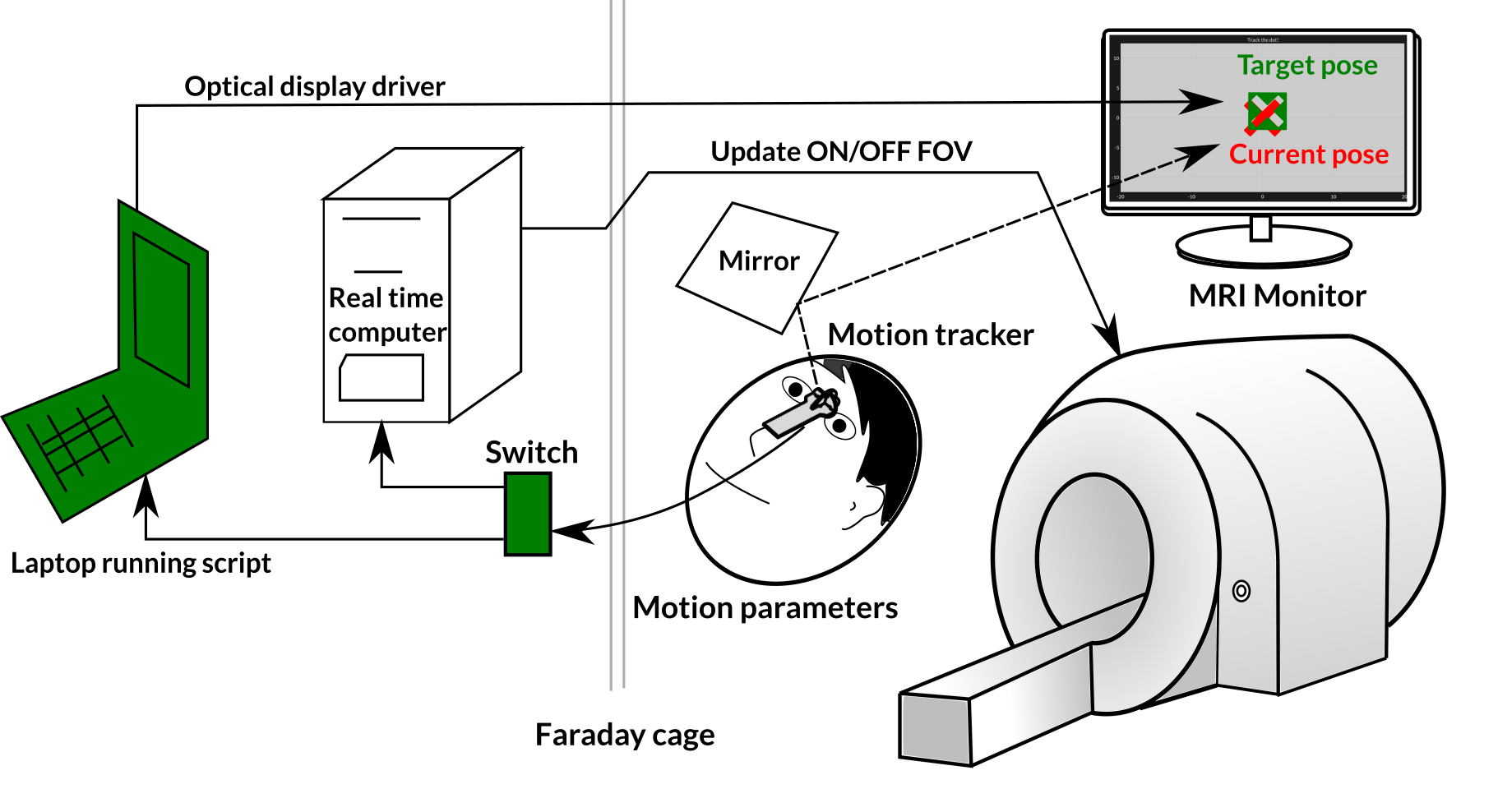
Figure 1: Experimental setup, a switch is inserted into the local scanner network allowing the laptop, running the visualisation tool, to receive the motion packets that would be used by the real time computer to update the FOV. The volunteer see's their current and the target motion on an MRI compatible display connected to the laptop.
Figure 2: Animation showing the information displayed to the volunteer. Their task is to position the red cross within the green cross negative. In the actual implementation the movement appears much smoother than the reduced frame rate GIF animation presented here.
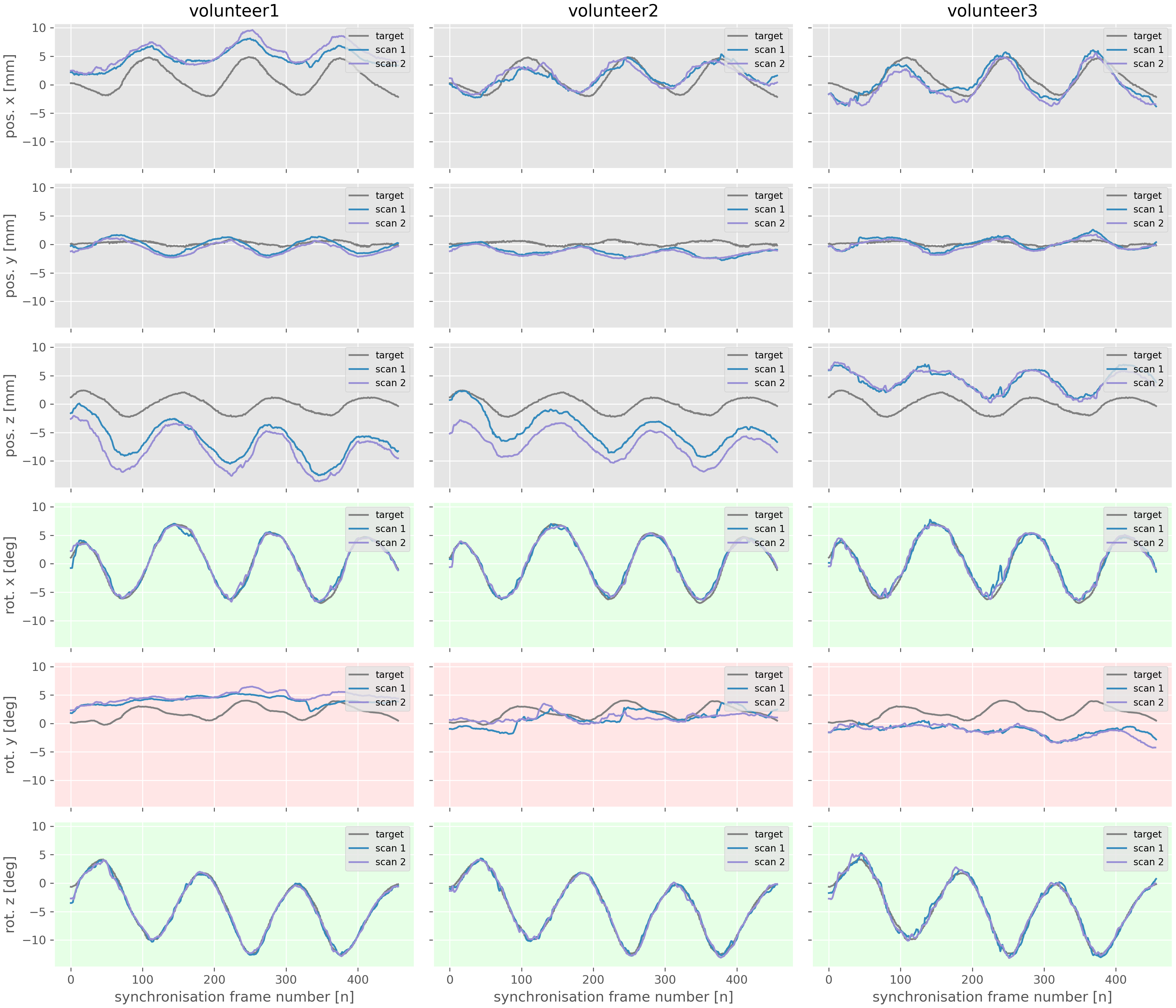
Figure 3: The axes with a green background are the two degrees of freedom in orientation that are represented by the position of the marker on the display. Notice how accurately the three volunteers are able to trace these degrees of freedom for both scan 1 (blue) and scan 2 (purple). The axis with a red background represents the tilting degree of freedom. In this case the volunteers struggle to replicate the target, suggesting that a larger marker may be beneficial. The translations have a constant offset, but are still strongly correlated with the target suggesting rolling motion.
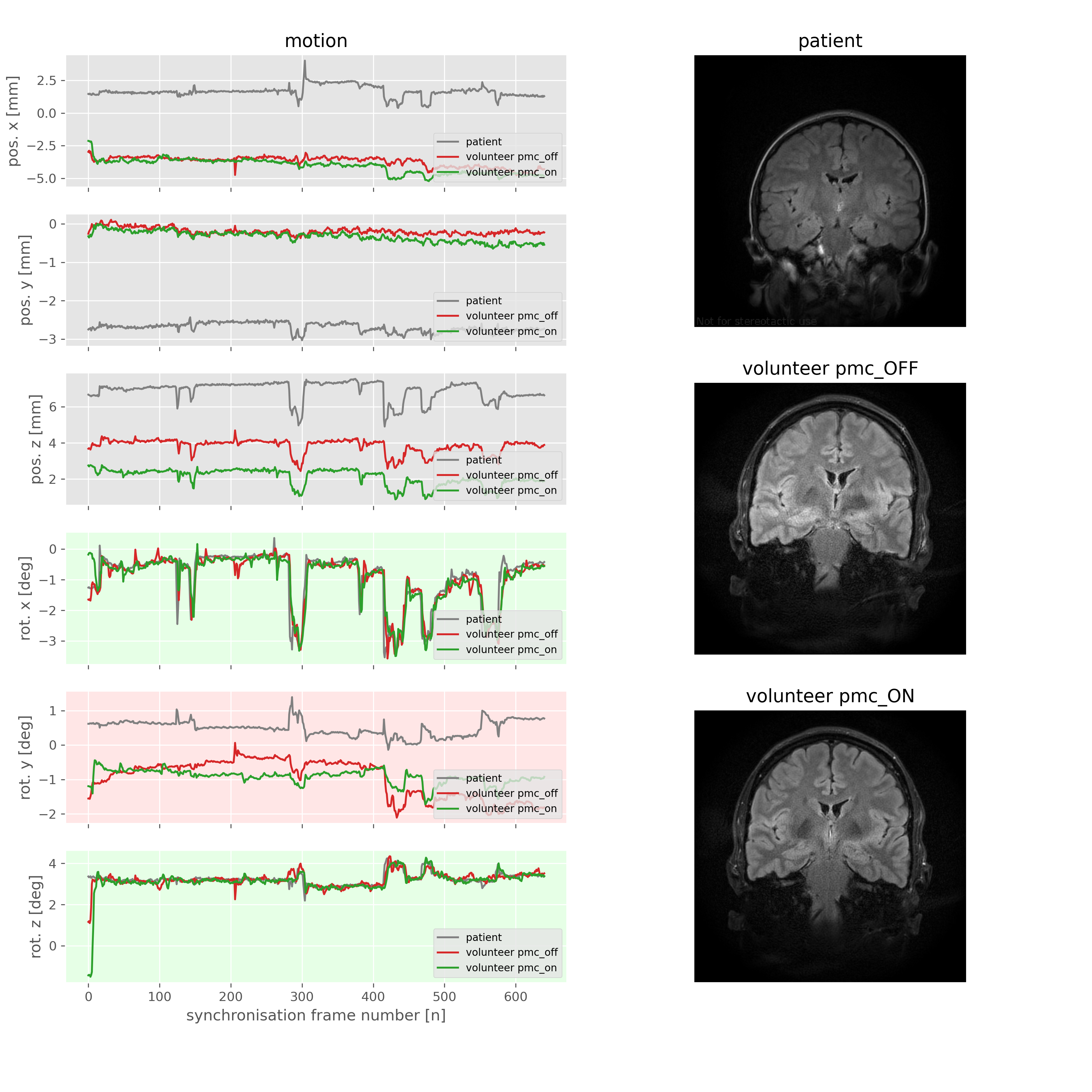
Figure 4: Reproducing motion from a patient scan. The volunteer was able to replicate the child’s motion profile, once with PMC on (green) and once with PMC off (red). We could then see the effect that the through plane motion would have had on the image contrast if prospective motion was not applied. This gives us a better understanding of the benefit of PMC in this case.
DOI: https://doi.org/10.58530/2022/0855