0841
Accelerated MRI Thermometry with Multi-Echo Multi-Slice GRE1Insightec Ltd, Haifa, Israel
Synopsis
An accelerated multi echo GRE sequence is presented for Focused Ultrasound Thermometry. An under sampled k space dataset is acquired during heating, to reduce scan time and enable multi-slice acquisition. Prior to heating, a fully sampled baseline image is acquired. Based on the baseline image, an iterative reconstruction algorithm fills-in the missing lines of each hot image. Accelerations of up to x15 with 16 echoes enable acquisition of 5 – 10 slices in 3.5 sec. Real-time reconstruction of 800 msec/5 slices was implemented on a FUS-MRI machine.
Introduction
Transcranial MR‑guided heating with Focused Ultrasound (FUS) is used to treat brain disorders noninvasively. The pulse sequence we currently use for heating is a 2D gradient-echo with multi-echo acquisition1 (ME-GRE) that acquires one 3 mm slice every 3.5 sec. Increasing the spatial coverage and resolution while maintaining scan time and Temperature SNR (Tsnr) will reduce treatment duration and improve accuracy. Various methods were proposed to increase spatial coverage at the same scan time2 – 4. In this work we present an accelerated Cartesian ME-GRE with up to x15 acceleration, higher Tsnr, and thinner slices. All heating experiments were done on 1.5T and 3T scanners using the Insightec Exablate 4000 system, with a two-channel receive coil immersed in a bath of cooling water.Methods
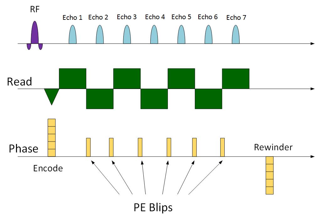
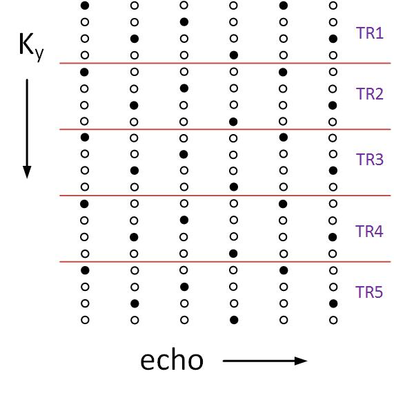
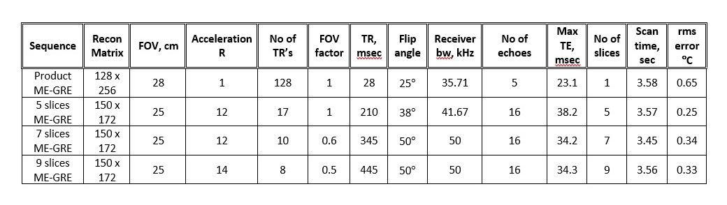
The pulse sequence we use is a multi-slice bipolar ME-GRE with up to 18 echoes. Gradient blips are added between the echoes (Fig. 1), such that the ky-TE plane is traversed in a zigzag pattern, like EPTI5 (Fig. 2). To accelerate data acquisition by R, only 1/R of the lines are sampled. The rest are filled by the reconstruction. Fig. 2 demonstrates the ky-TE trajectory with 20 ky lines, 6 echoes, and R = 4 such that only 5 TRs are acquired. Each point on the ky-TE plane in Fig. 2 represents a fully sampled kx line. Table 1 shows real imaging parameters, with R between 12 to 15 and 5 to 9 slices acquired in ~3.5 sec. Prior to heating, a fully sampled “reference” image is acquired. The Thermal map of each subsequent under-sampled “hot” image is computed relative to this “reference” image.Reconstruction: The algorithm we use is an iterative Alternating Projections onto Convex Sets (POCS) procedure6 which alternately imposes 2 constraints at each iteration: 1) the phase difference between each echo of the “reference” and “hot” images is linear in TE. 2) data consistency. Replace k-space points with the sampled data at the sampled locations. The linear phase constraint is imposed using the Ahn and Cho algorithm7 to prevent aliasing. Once aliasing is removed, a simple straight-line fitting is used. Convergence is obtained in 20 – 40 iterations.
Denoising: Wavelet denoising with Sigmoid thresholding8 can be added to the POCS iterations. Since the wavelet transform is computer-expansive, the Sigmoid thresholding is employed only in the last 5 iterations with ~30% to 50% SNR improvement.
Outer Volume Suppression: To reduce scan time and reduce (eliminate) the signal of the cooling water bath, we use Outer Volume Suppression (OVS). This is done with a dual-band VSS RF pulse9. Excellent outer volume signal suppression is obtained by flipping the amplitudes of the spoiler gradients, which eliminate inter-slice stimulated echoes.
Imaging parameters selection: From Table 1, high acceleration R (≤15) is obtained. This means less acquired ky lines and lower SNR. To compensate and exceed the SNR of the fully sampled sequence, we use long TR’s (250 ‑ 500 msec), long echo train (up to 18) and long TE’s (up to 40 msec). Also, the “reference” image uses the same long TR with higher SNR. Therefore, as seen in Table 1, the accelerated scans' Temperature SNR (Tsnr) is higher than the single slice fully sampled scan.
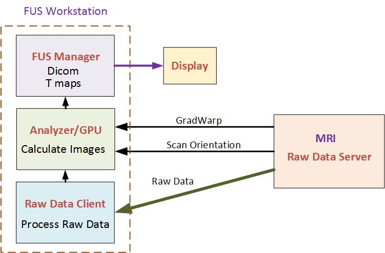
Real-Time Reconstruction: The reconstruction algorithm was implemented on a GPU and fully integrated with the MRI computer and FUS workstation. The integrated architecture of the FUS workstation and scanner during reconstruction is shown in Fig. 3. This reconstruction is fast, about 800 msec for 5 slices and 16 echoes. It is completely transparent to the user.
Results
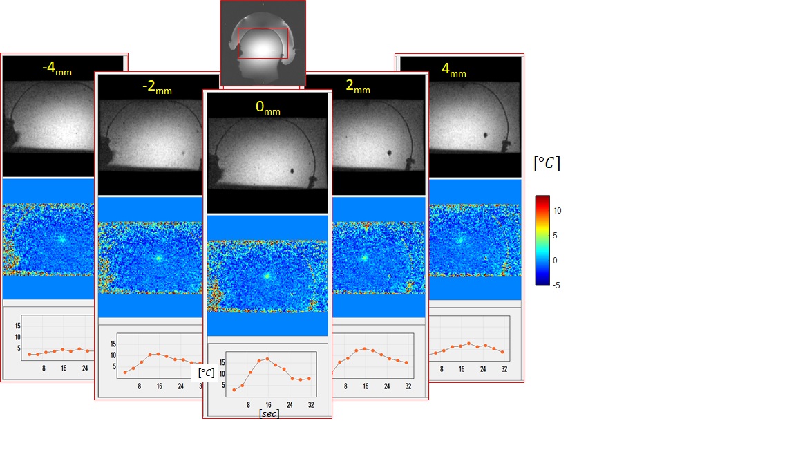
The algorithm was tested on phantoms and volunteers at 1.5T and 3T. The results in Table 1 and the heating in Fig. 4 were acquired using a gel phantom shaped like a human head with relaxation times (T1, T2, T2*) of gray matter. Due to the high Tsnr, we use a 2 mm slice (Fig. 4).Discussion
An alternative method to reduce imaging time is to use multi-shot epi10. We use the method presented here because 1) the epi acquisition window is limited to only 8 msec to avoid spatial distortions, and there is only one TE. This limits the Temperature SNR10. 2) Our receive coil is immersed in water, which generates high signal and nonlinear phase close to the coil wires. Often this causes failure of the epi calibration in oblique directions, resulting in image ghosts. The simple algorithm presented above is robust, but not convex. Therefore, it is necessary to ensure convergence to the global minimum for a large frequency difference Df (due to Temperature difference) and long TE’s. This is done by progressively applying it to echoes with increasing TE. At first it is applied to echoes 1 to 7, then to echoes 1 to 10 and finally to echoes 1 to 16. This ensures robust convergence for Df ≤ 50 Hz and TE’s ≤ 45 msec.Conclusion
We presented an iterative algorithm to accelerate thermal imaging. High acceleration (R ≤ 15) was achieved, which enabled us to scan up to 10 slices in 3.5 sec with high-Temperature SNR. Real-time reconstruction was implemented on a FUS MRI machine.Acknowledgements
We acknowledge the support of Yoav Levy and the help of Asaf Hertz with the FUS workstation software.References
1) Zur Y., Multi echo GRE for thermal imaging, Proceedings ISMRM 2014, p. 3713.
2) Marx M, Butts Pauly K, Improved MRI Thermometry with multiple echo spirals, Mag. Res. Med. 2016; 76(3), 747 – 756.
3) Todd N. et al, toward real time availability of 3D temperature maps created with temporally constrained reconstruction, Mag. Res. Med. 2014; 71, 1394 – 1404.
4) Jonathan SV., Grissom WA. Volumetric MRI Thermometry Using 3D Stack of Stars EPI Pulse Sequence, Mag. Res. Med. 2018; 79, 2003 – 2013.
5) Wang F, Dong Z, Reese T, Bilgic B, Manhard M, Chen J, Polimeni J, Wald L, Setsompop K, Echo planar time-resolved imaging (EPTI), Mag. Res. Med. 2019; 81, 3599 – 3615.
6) Robert J Marks II, Handbook of Fourier Analysis and Its Applications, Oxford University Press 2009, p. 496.
7) Ahn CB, Cho ZH, A new phase correction method in NMR imaging, IEEE Trans. Med. Imag. 1987; MI‑6, 32 – 36.
8) Atto A, Pastor D, Mercier G, Wavelet shrinkage: unification of basic thresholding functions and thresholds. Signal, Image and Video Processing, Springer Verlag, 2011, 5 (1), pp.11-28. https://hal.archives-ouvertes.fr/hal-00732360/document.
9) Osorio J, Xu D, Cunningham C, Chen A, Kerr A, Pauly J, Vigneron D, Nelson S, Design of cosine modulated very selective suppression pulses for MR spectroscopic imaging at 3T, Mag. Res. Med. 2009; 61, 533 – 540.
10) Odeen H, Rieke V, Patil S, Roberts J, Bhat H, Bolster B, Parker D, Comparison of cartesian MR thermometry approaches for focused ultrasound brain applications, Proceedings ISMRM 2019, abstract 3822.
Figures