0712
An integrated 64-channel receive array design for 7 Tesla head and torso MRI of young infants1Biomedical Engineering Department, School of Biomedical Engineering and Imaging Sciences, King's College London, London, United Kingdom, 2Centre for the Developing Brain, School of Biomedical Engineering and Imaging Sciences, King's College London, London, United Kingdom
Synopsis
7T MRI has potential for adding value in studies of infant brain and heart. In this study we introduce the first integrated high channel count receive array designed to enable both head and torso imaging of young infants at 7T. The array performance was evaluated in terms of noise correlation matrix, signal-to-noise ratio, and spatial coverage. The initial results are promising with the array providing a large coverage of the targeted regions in phantom. After further safety checking, the next step will be to conduct in-vivo studies, paving the way for future high performance infant examinations at 7T.
Introduction
7T MRI has the potential for adding value in studies of infant brain and heart, particularly given the smaller subject size compared to adults. RF safety studies are paving the way1,2 and there has been a study of the neonatal brain that used an adult head coil3. At lower field, dedicated receiver coils for young infants have proved a valuable addition4-7. Previously we presented a design of an 8 channel dipole array designed for young infant examinations at 7T8. In this study, we have explored the design of a high channel count receiver array to facilitate both head and torso imaging of young infants up to 3 months of age at 7T.Methods
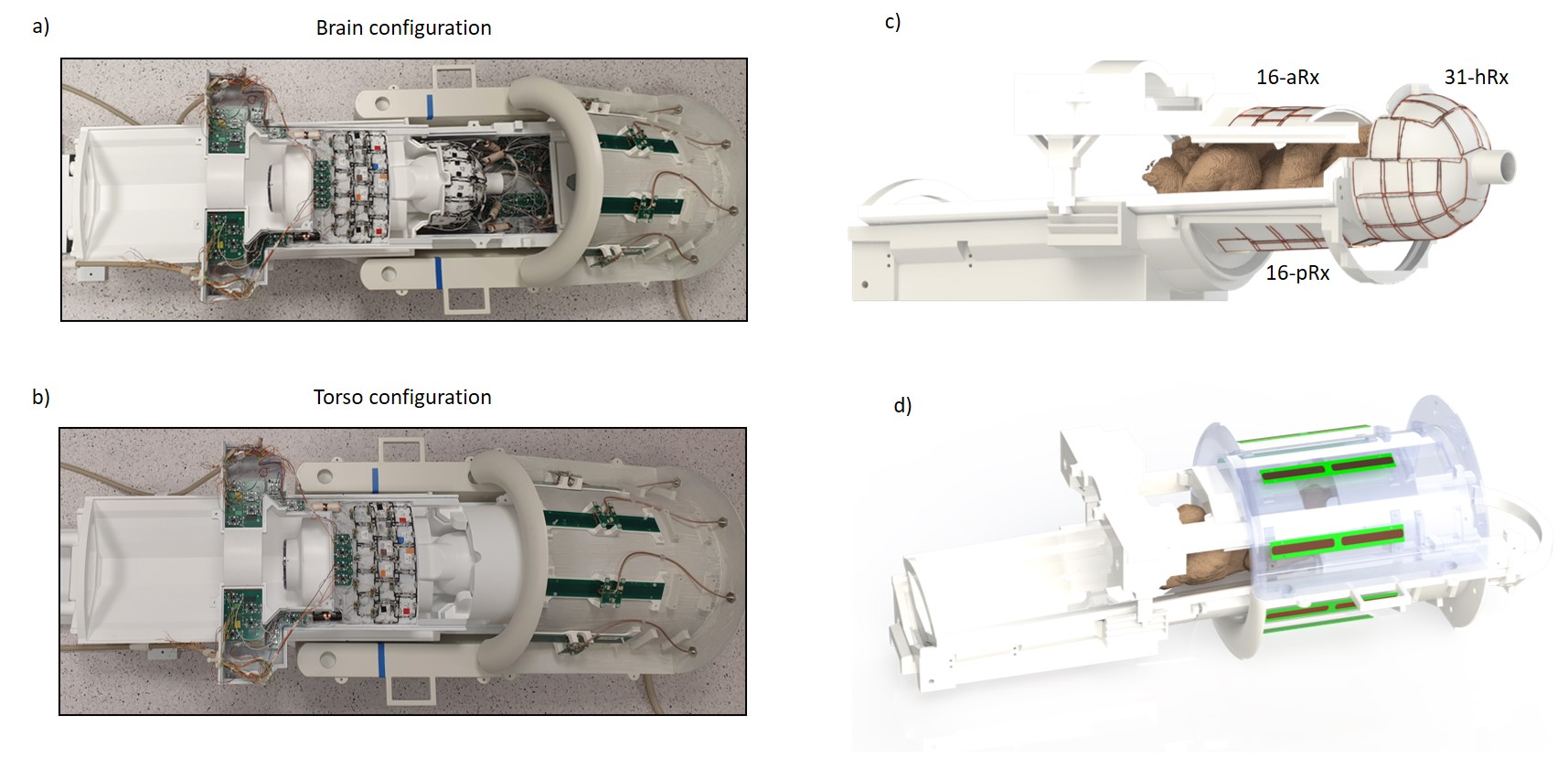
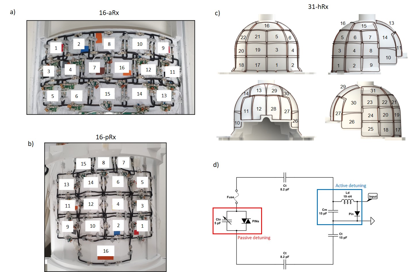
A complete setup of the integrated coil including the 8-channel transmit dipole array8, the multi-channel receive array with its associated circuitry and the mechanical structures9 optimized for whole-body fitting of young infants, up to 3-months in age is shown in Fig.1. Two main configurations, infant brain and torso, are enabled (Fig.1a-b).The receive array consists of the 16-channel anterior torso array (16-aRx), the 16-channel posterior torso array (16-pRx), and the 31-channel head array (31-hRx). The 16-aRx was designed with 3-rows loops with dimensions of 45x35 mm to 42x40 mm (Fig.2a). The 16-pRx has 3-rows of four loops, and a large loop was placed at the foot-end of the array to extend the longitudinal coverage (Fig.2b). An integrated torso and head design was achieved with the three loops placed at the junction between the posterior array and the head array to provide continuous spatial coverage along the infant’s spine. The 31-hRx consisted of 31 loops geometrically arranged on a purpose-designed helmet (Fig. 2c). A last large loop is meant to be added on top of the helmet to complete the 64-channel receive array design. The minimal distance between the arrays and the load was 5 mm for the 16-aRx, 10 mm for the 16-pRx, and 9 to 22 mm for the 31-hRx.
Geometrically decoupled loop arrays were each built using silver-plated wires (diameter = 1.1 mm) and included an active detuning circuit enabled with a PIN-diode (MA4P7470F-1072T,MACOM,USA) placed across the matching capacitor Cm (ATC100B,American Technical Ceramics,USA) and connected in series with a hand-wounded inductor Ld (Fig.2d). In addition, passive detuning was ensured using a double pair of crossed diodes (MA44781,MACOM,USA) connected in parallel to the tuning capacitor Ctv (JZ150,Knowles Voltronics,USA). A fuse (RS Pro,315 mA) was also added to assure safety (Fig.2d). The preamplifier decoupling method10 was implemented by connecting, through a half-wavelength or full-wavelength coaxial cable (K_01152-07,Huber-Suhner,Switzerland), a low-input impedance preamplifier (WMM7RP,WantCom Inc.,Minnesota,USA) across the PIN-diode used for detuning to create a virtual open circuit to minimize the next-neighborhood decoupling. In-house-made floating baluns were integrated to minimize common-mode currents.
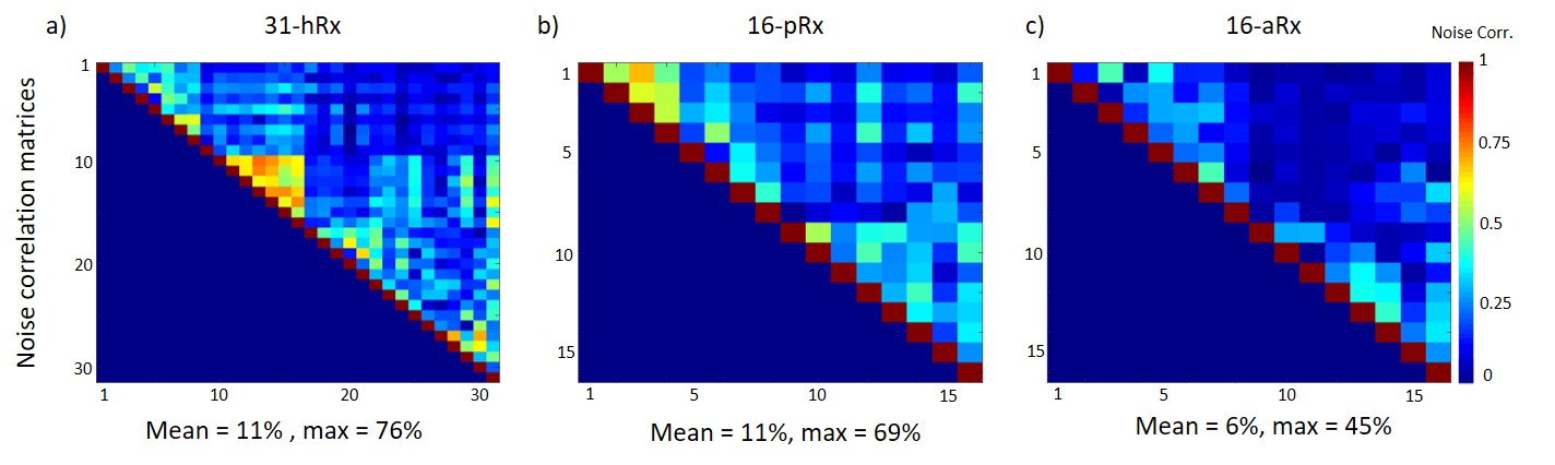
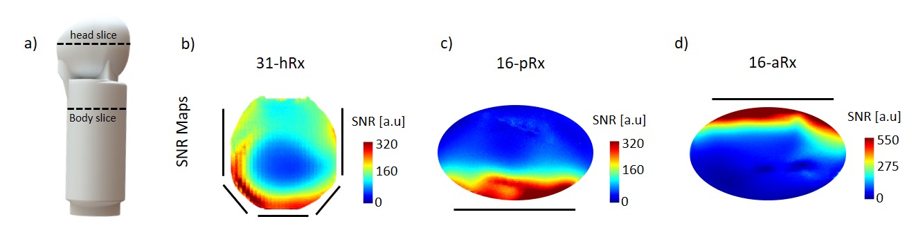
MR data was acquired on a 7T MR scanner (MAGNETOM Terra, Siemens, Germany) with 8x2kW RF amplifiers in prototype research configuration using an in-house built infant phantom11 (Fig.4a). Each array was considered separately. SNR maps and normalized noise correlation matrices were measured in a transverse slice at the isocentre of the transmit coil with the phantom positioned appropriately (Fig. 4a) using a 2D-GRE sequence (signal and noise-only) acquired without acceleration (TR/TE = 100/10 ms, 1x1x1 mm3, FA = 25 deg, matrix = 300 x 304). In addition, SNR maps were normalized by sin(flip angle), as measured in circularly-polarized mode (CP) using the actual-flip-angle method12.
Results
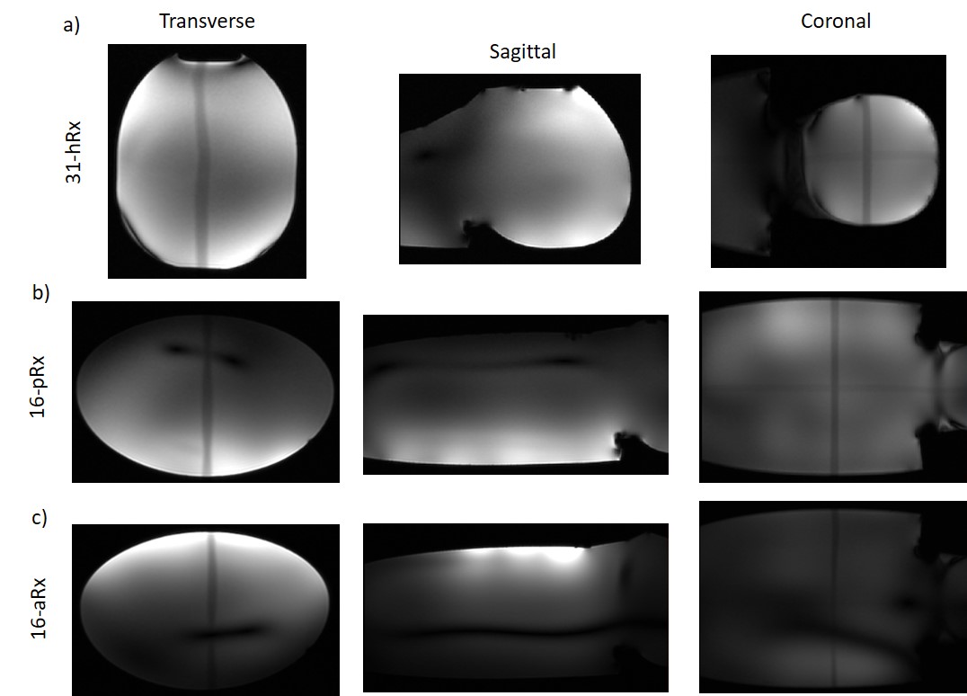
The noise correlation matrix for the anterior array (16-aRx) showed good decoupling between all the loops while a maximum value of 76% was observed for the 31-channel head array around the channel 14 (Fig.2). A comparable maximum (69%) was observed for the posterior array (16-pRx) around the channel 2. The SNR levels were significantly higher for the 16-aRx compared to the 16-pRx, and both parts had higher SNR than the 31-hRx (Fig.4b-d). The three sub-parts demonstrated an efficient coverage of the regions-of-interest (Fig.5). Notably, the 16-pRx efficiently provided a longitudinal coverage in the neck-like region of the infant phantom (Fig.5b).Discussion and conclusion
In this work, we described the design and first testing of a dedicated integrated multi-channel receive array for brain and torso imaging of young infants at 7T. The relatively high noise correlation levels observed for the 31-hRx and 16-pRx must be further improved. This may cause the differences in SNR observed with the 16-aRx torso array although the distance between the load and the receive loops was also different in each situation. After refining the coil performance and further safety checking, the next step will be to conduct in-vivo studies, paving the way for future high-performance infant examinations at 7T.Acknowledgements
This work was supported by core funding from the Wellcome/EPSRC Centre for Medical Engineering [WT203148/Z/16/Z], the Wellcome Trust Collaboration in Science grant [WT201526/Z/16/Z], and by the National Institute for Health Research (NIHR) Biomedical Research Centre based at Guy’s and St Thomas’ NHS Foundation Trust and King’s College London and/or the NIHR Clinical Research Facility. The views expressed are those of the author(s) and not necessarily those of the NHS, the NIHR or the Department of Health and Social Care.References
1. Malik SJ, Hand JW, Satnarine R, Price AN, Hajnal JV (2021) Specific absorption rate and temperature in neonate models resulting from exposure to a 7T head coil. Magnetic Resonance in Medicine 86:1299–1313.
2. Clement J, Ipek Ö (2020) RF safety evaluation of an 8-channel dipole array for neonatal brain and cardiac MR at 7T parallel-transmit. Annual Meeting of ESMRMB, #1402
3. Annink KV, Aa NE van der, Dudink J, Alderliesten T, Groenendaal F, Lequin M, Jansen FE, Rhebergen KS, Luijten P, Hendrikse J, Hoogduin HJM, Huijing ER, Versteeg E, Visser F, Raaijmakers AJE, Wiegers EC, Klomp DWJ, Wijnen JP, Benders MJNL (2020) Introduction of Ultra-High-Field MR Imaging in Infants: Preparations and Feasibility. American Journal of Neuroradiology. doi: 10.3174/ajnr.A6702
4. The developing Human Connectome Project. http://www.developingconnectome.org/
5. Keil B, Alagappan V, Mareyam A, McNab JA, Fujimoto K, Tountcheva V, Triantafyllou C, Dilks DD, Kanwisher N, Lin W, Grant PE, Wald LL (2011) Size-optimized 32-channel brain arrays for 3 T pediatric imaging. Magnetic Resonance in Medicine 66:1777–1787.
6. Hughes EJ, Winchman T, Padormo F, Teixeira R, Wurie J, Sharma M, Fox M, Hutter J, Cordero‐Grande L, Price AN, Allsop J, Bueno‐Conde J, Tusor N, Arichi T, Edwards AD, Rutherford MA, Counsell SJ, Hajnal JV (2017) A dedicated neonatal brain imaging system. Magnetic Resonance in Medicine 78:794–804.
7. Ghotra A, Kosakowski HL, Takahashi A, Etzel R, May MW, Scholz A, Jansen A, Wald LL, Kanwisher N, Saxe R, Keil B (2021) A size-adaptive 32-channel array coil for awake infant neuroimaging at 3 Tesla MRI. Magnetic Resonance in Medicine 86:1773–1785.
8. Clément J, Tomi-Tricot R, Satnarine R, Hand JW, Malik SJ, Zivkovic I, Webb A, Hajnal JV, Ipek Ö (2020) 8-channel dipole array for 7 Tesla neonatal brain and cardiac MRI. 28th Annual Meeting of ISMRM, 4618
9. Clement J, Colford K, Hughes EJ, Arichi T, Edwards AD, Hajnal JV, Ipek Ö (2021) Design of a neonatal head and cardiac imaging system and parallel-transmit volume/receive phased array for 7T MRI during early infancy. 29th Annual Meeting of ISMRM, #2267
10. Roemer PB, Edelstein WA, Hayes CE, Souza SP, Mueller OM (1990) The NMR phased array. Magnetic Resonance in Medicine 16:192–225.
11. Clement J, Ipek Ö (2021) A robust validation of parallel-transmit dipole array simulation setup for infant MRI at 7 Tesla. Annual Meeting of ESMRMB, #150
12. Yarnykh VL (2007) Actual flip-angle imaging in the pulsed steady state: a method for rapid three-dimensional mapping of the transmitted radiofrequency field. Magn Reson Med 57:192–200.
Figures