0710
Novel Dipole/Loop Combined Arrays for Human Whole Brain Imaging at 7 T
Nikolai I. Avdievich1, Anton V Nikulin1,2, Loreen Ruhm 1, Arthur W Magill 3, Anke Henning4, and Klaus Scheffler1,2
1High-Field MR Center, Max Planck Institute for Biological Cybernetics, Tübingen, Germany, 2Biomedical Magnetic Resonance, University of Tübingen, Tübingen, Germany, 3Medical Physics in Radiology, German Cancer Research Center, Heidelberg, Germany, 4Advanced Imaging Research Center, University of Texas Southwestern Medical Center, Dallas, TX, United States
1High-Field MR Center, Max Planck Institute for Biological Cybernetics, Tübingen, Germany, 2Biomedical Magnetic Resonance, University of Tübingen, Tübingen, Germany, 3Medical Physics in Radiology, German Cancer Research Center, Heidelberg, Germany, 4Advanced Imaging Research Center, University of Texas Southwestern Medical Center, Dallas, TX, United States
Synopsis
The advancement of clinical applications of 7T MRI depends heavily on the development of new RF coil designs. Recent works based on Ultimate Intrinsic SNR theory demonstrated that an optimal central SNR at 7T requires combining surface loops with dipole antennas. In this work, we developed and evaluated two novel 32-element 7T human head loop/dipole array designs. Both coils demonstrated superior Tx-efficiency, longitudinal coverage, and SNR in comparison to widely used commercial array coil. While the transceiver (TxRx)-dipole/receive(Rx)-loop array demonstrated best SNR, the TxRx-loop/Rx-dipole array showed the best Tx-efficiency. In addition, double-row TxRx-loop/Rx-dipole array provides 3D RF shimming capability.
Purpose
To improve the transmit and receive performance of array coils for human whole-brain imaging at 7T.Introduction
The advancement of clinical applications of Ultra-High Field (UHF, >7T) MRI depends heavily on development of new RF coil designs. Currently, the number of commercially available 7T head RF coils is limited, implying a need for novel reliable coil designs that offer superior transmit (Tx) and receive (Rx) performance. Recent works based on Ultimate Intrinsic SNR (UISNR) theory demonstrated that an optimal central SNR at UHF requires contribution of two current patterns associated with loops and dipole antennas (1-3). In this work, we developed, constructed and compared two novel 7T 32-element head array coil designs both consisting of loops and dipoles.Methods
Our design strategy was based on two major ideas. Firstly, we combined loops and dipoles for optimal SNR near the head center. Secondly, we simplified the array design by decreasing the total number of Tx- and Rx-elements and placing all of them into a single layer at the same distance from the head. Bringing Tx-elements closer to the head also improves the Tx-efficiency (B1+/√P) (4). Thus, the general idea of our design approach is that the total number of array elements should not exceed the number of available Rx-channels, e.g. 32 (5). This implies that some of the array elements are used for both transmission and reception, i.e. transceiver (TxRx), and the remaining elements as Rx-only. This also minimizes the number of active detuning circuits, which aren’t required for the TxRx-elements. Based on the above strategy, we developed two novel 32-element array designs. In the first design, we combined 8 TxRx-dipoles with 24 Rx-loops (Fig.1A). The second design consisted of 16 TxRx-loops and 16 Rx-dipoles (Figs.1B,1C). In both designs, we used novel folded-end dipoles, which were recently developed in our laboratory and used in designing 7T (6) and 9.4T (7-9) head array coils. This type of dipoles improves longitudinal coverage (8,9) and minimizes resonance frequency shift (7) due to head size variation. In the TxRx-dipole/Rx-loop design, 3 rows of 8 overlapped Rx-loops were placed on a tight-fit holder (19-cm width, 22-cm height, 18-cm length) with 8 longer TxRx-dipoles (25-cm length) positioned in the center of the loops (Fig.1A). The TxRx-loop/Rx-dipole array was larger (20.5-cm width, 23-cm height, 17.5-cm length) and consisted of 2 rows of 16 TxRx-loops (Fig.1B) and 14 Rx-dipoles positioned in the center of each loop (Fig.1C). Loops across the eyes had no dipoles. Instead, two additional crossed Rx-dipoles were placed at the superior head location. Neither coil had an RF shield. TxRx-dipole/Rx-loop array included a local superior shield (Fig.1A). Electromagnetic (EM) simulations were performed using CST Studio Suite 2020 (Dassault Systèmes, Vélizy-Villacoublay, France) and the time-domain solver based on the finite-integration technique. All data were acquired on a Siemens Magnetom 7T human imaging system. We compared the new arrays to a commercial 8-Tx/32-Rx array coil (Nova Medical, Wilmington, MA, USA).Results and Discussion
Fig.2 shows a comparison of the developed arrays’ Tx-performance with that of the commercial array. All arrays were driven in the quadrature circular polarized (CP) mode, which corresponds to the 45° phase increment for an 8-element array. Averaged over the 130-mm transversal slab, <B1+>/√P measured 7.95(32%,), 9.13(28%), 10.92(28%) μT/√kW (SD–standard deviation) for the commercial array, TxRx-dipole/Rx-loop array, and TxRx-loop/Rx-dipole array, respectively. Both developed arrays provided better longitudinal coverage down the brain stem (Fig.2) than the commercial coil. The TxRx-loop/Rx-dipole array, however, demonstrated lower B1+ values at the superior head locations (Fig.2C). The longitudinal coverage and SAR-efficiency (<B1+>/√pSAR, where pSAR is the peak local 10g SAR) can be further improved (10) by an introduction of an additional phase shift between the rows (Fig.3). EM simulations showed that the 60° phase shift provided better SAR-efficiency, while the best coverage and homogeneity were obtained at the 80° phase shift. Experimentally measured <B1+>/√P was 10.37(26%) and 9.78(23%) μT/√kW (SD) for the 60° and 80° phase shifts, respectively, which is 30% and 23% higher than that of the commercial coil. Fig.4 shows a comparison of SNR. The TxRx-loop/Rx-dipole array demonstrates similar to the commercial coil SNR at the periphery and ~10% higher SNR near the center of the brain. TxRx-dipole/Rx-loop array shows substantially higher SNR both at the periphery (~40%) and the center (~20%). Finally, Fig.5 shows invivo GRE and MP2RAGE images obtained using the developed arrays. Both arrays provided whole-brain coverage. TxRx-dipoles, however, had somewhat better coverage down the brain stem.Conclusion
We developed, constructed, and evaluated two novel 32-element 7T human head array coil designs both combining loops and dipoles. Both arrays demonstrated superior Tx-efficiency, longitudinal coverage, and SNR in comparison to the widely used commercial array coil. While, the TxRx-dipole/Rx-loop array demonstrated the best SNR, the TxRx-loop/Rx-dipole array showed the best Tx-efficiency. In addition, double-row TxRx-loop/Rx-dipole array provides 3D RF shimming capability that further improves B1+ homogeneity when combined with parallel transmission (pTx).Acknowledgements
Funding by the European Union (ERC Starting Grant, SYNAPLAST MR, Grant Number: 679927; ERC Advanced Grant SpreadMRI, Number: 834940) is gratefully acknowledged.References
1) Vaidya MV et al. Conc Magn Reson Part B 2014; 44B(3):53-65. 2) Lattanzi R, Wiggins GC, Zhang B, Duan Q, Brown R, and Sodickson DK. Magn Reson Med 2018;79(3):1789-1803. 3) Pfrommer A and Henning A. Magn Reson Med 2018;80(5):2122-2138. 4) Avdievich NI, Hoffmann J, Shajan G, Pfrommer A, Giapitzakis IA, Scheffler K, Henning A. NMR in Biomed 2017, 30(2);1-12. 5) Avdievich NI, Giapitzakis IA, Bause J, Shajan G, Scheffler K, Henning A. Magn Reson Med 2019; 81(5): 3392-3405. 6) Avdievich NI, Solomakha G, Ruhm L, Magill AW, Scheffler K. NMR in BioMed 2021;34(8):1-14. 7) Avdievich NI, Solomakha G, Ruhm L, Scheffler K, Henning A. Magn Reson Med 2019;82:811–824. 8) Avdievich NI, Solomakha G, Ruhm L, Bause J, Scheffler K, Henning A. Magn Reson Med 2020; 84:3453–3467. 9) Avdievich NI, Solomakha G, Ruhm L, Henning A, Scheffler K. Magn Reson Med 2021;86:581–597. 10) Avdievich NI, Giapitzakis IA, Pfrommer A, Henning A. NMR in BioMed 2018, 31(9): 1-13.Figures
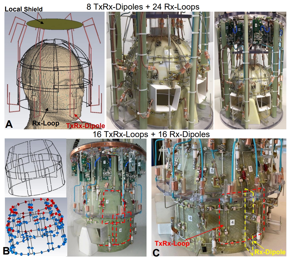
Figure 1. A) EM
simulation model and photos of the 32-element 8 TxRx-dipole/ 24 Rx-loop head
array coil. The cover is removed for
better visualization. The EM array model is loaded by the Duke voxel model. B) EM
simulation model and photo of the 16-loop TxRx-array before introduction of
Rx-dipoles. C) Photo of the final 32-element 16 TxRx-loop/ 16 Rx-dipole head
array design after introduction of Rx-dipoles. Examples of a TxRx-loop and
Rx-dipole are shown in red and yellow, respectively.
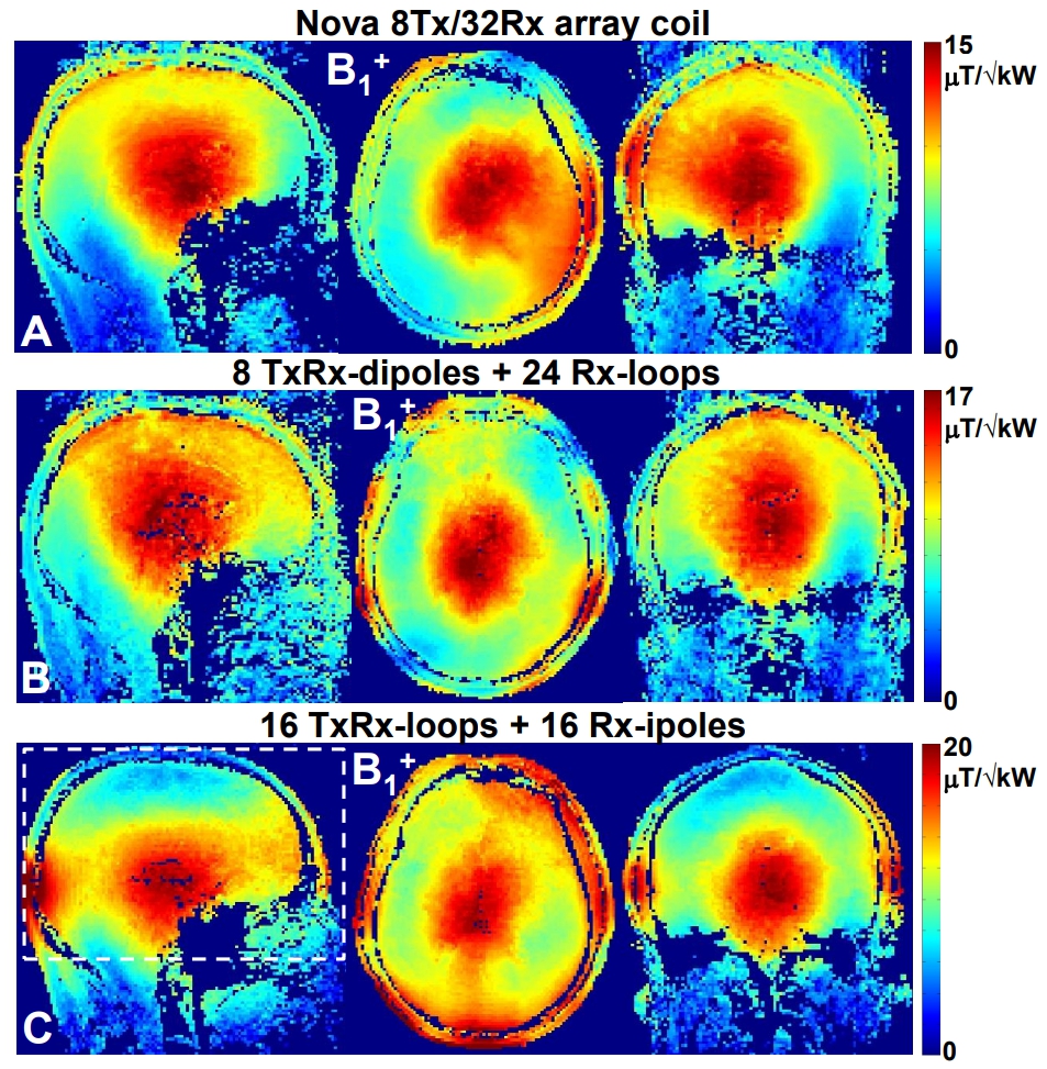
Figure 2. Central sagittal, transversal, and coronal in-vivo B1+ maps obtained
for a male subject (the head circumference of 570 mm) using the commercial (A),
TxRx-dipole/ Rx-loop (B) and TxRx-loop/ Rx-dipole human head array coils. All map are normalized to corresponding maximums of the B1+ field. White
dashed line (Figure 2C) shows 130-mm transversal averaging slab.
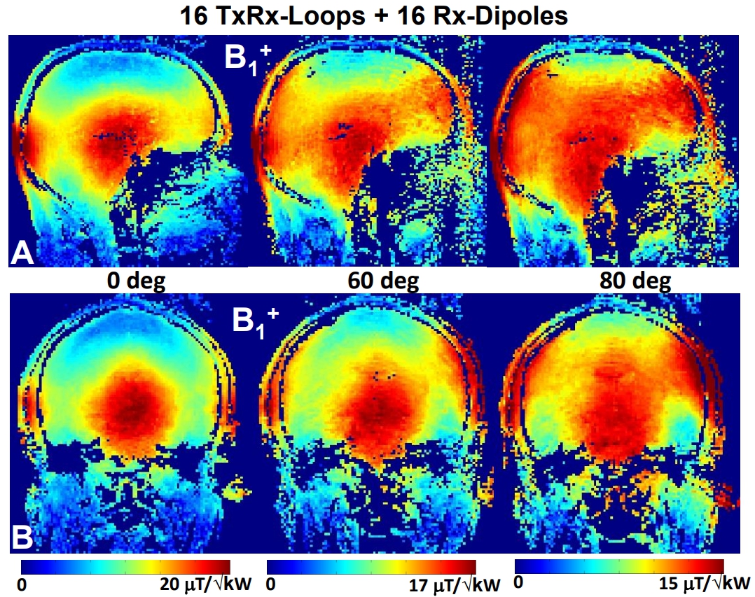
Figure 3. Central sagittal (A) and coronal (B) in-vivo B1+ maps obtained
for the same male subject as in Figure 2 using the developed double-row TxRx-loop/
Rx-dipole human head array coil. B1+
maps are obtained with 0°, 60°, and 80° phase shifts
between the rows.
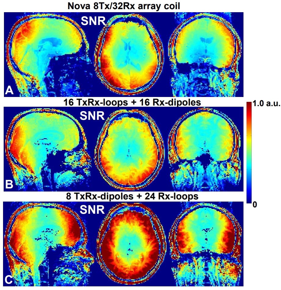
Figure 4. Central sagittal, transversal, and coronal in-vivo SNR maps
obtained for the same male subject as in Figure 2 using the commercial (A), and
the developed TxRx-dipole/ Rx-loop (B) and TxRx-loop/ Rx-dipole human head
array coils.
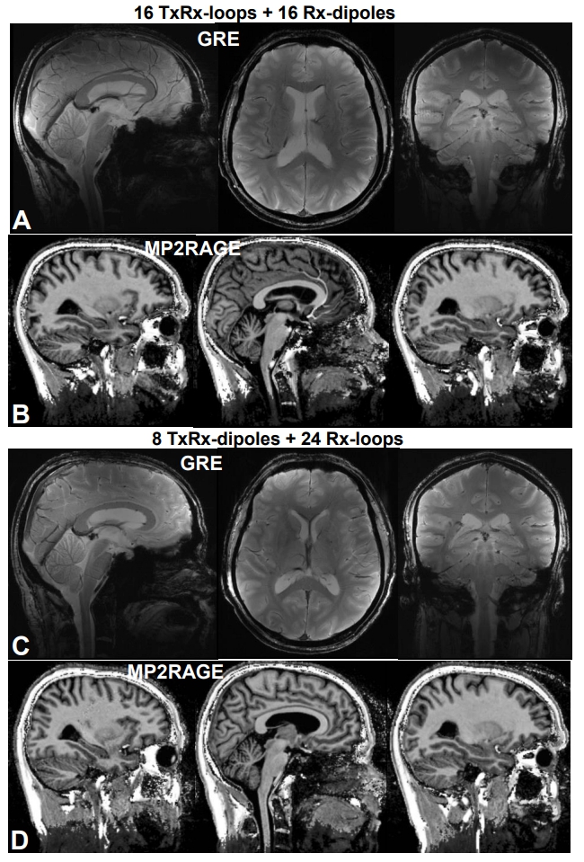
Figure 5. Central sagittal, transversal, and coronal in-vivo GRE (A,C)
and MP2RAGE (B,D) images obtained for the same male subject as in Figure 2
using the developed TxRx-loop/ Rx-dipole (A,B) and TxRx-dipole / Rx-loop (C,D)
human head array coils.
DOI: https://doi.org/10.58530/2022/0710