0709
The Double Bent Dipole (DBD): A hybrid element designed for combined RF/B0 shimming for imaging at 10.5T1Department of Radiology, Stanford University, Stanford, CA, United States, 2Center for Magnetic Resonance Research (CMRR), Department of Radiology, University of Minnesota, Minneapolis, MN, United States
Synopsis
In this work, we demonstrate a new double bent dipole geometry for use as a hybrid RF/B0 shimming element for 10.5T imaging, featuring two B0 shimming channels per RF channel. Initial simulations compare this element to standard dipoles and loops. Bench assessments and simulations further demonstrate excellent inter-element decoupling, and initial steps toward a 32-channel Tx/64-channel B0 array show promising results.
Introduction
The SNR increases afforded by ultra-high field (UHF) strength come at the cost of both B0 and B1 field homogeneity. B0 inhomogeneities are particularly problematic for susceptibility-sensitive sequences such as gradient echo, commonly used for functional MRI. Recently, the use of combined RF and B0 shimming arrays have been used to combat these homogeneity issues1–4. However, these implementations typically necessitate a large number of RF chokes to bridge lumped capacitive elements in the RF array, especially for UHF implementations, which can increase the complexity and cost of an array and lead to a decline in array performance4. Thus, element concepts that can minimize the need for these disruptive components are needed.Dipole elements are gaining in popularity and are especially advantageous at UHF5–8. The concept of geometrically bending a dipole has been previously suggested as a way to improve dipole decoupling and efficiency9–11. Here we introduce the concept of forming a combined RF/B0 element using a dipole. Because dipoles do not contain any distributed capacitive lumped elements, they represent an ideal DC current path that can be simultaneously used for B0 shimming with fewer RF chokes. Thus, bending the legs of a dipole to create a ‘loop-like’ structure can yield a useful geometry for B0 shimming. We modeled the RF performance of this “Double Bent Dipole” (DBD) in comparison to standard loop and dipole designs. Decoupling performance was evaluated in simulation and validated using bench measurements with prototype elements. Finally, simulated B0 performance of a preliminary 32-channel RF Tx/64-channel B0 shim array was investigated.
Methods
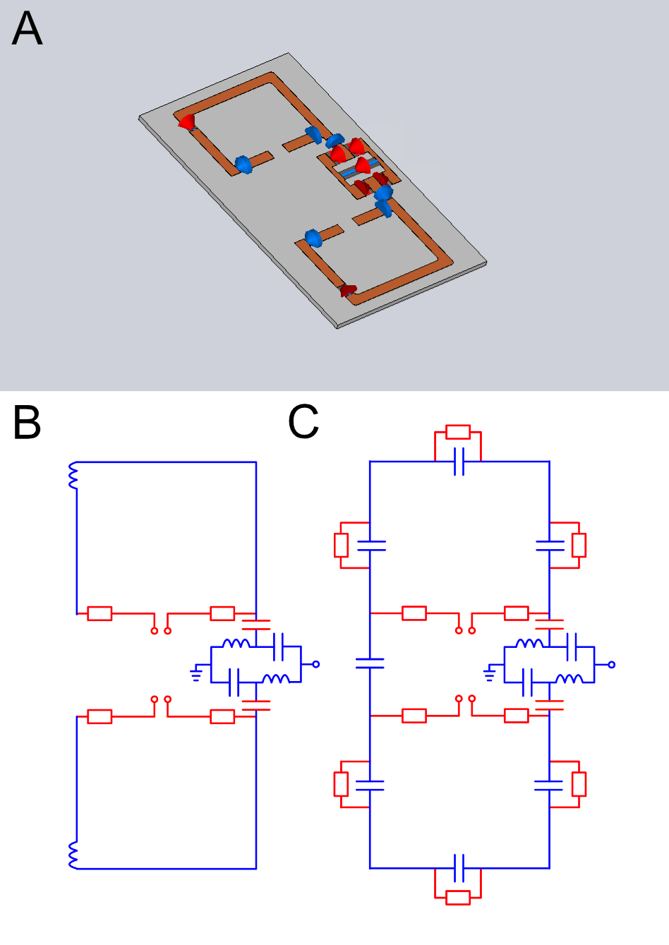
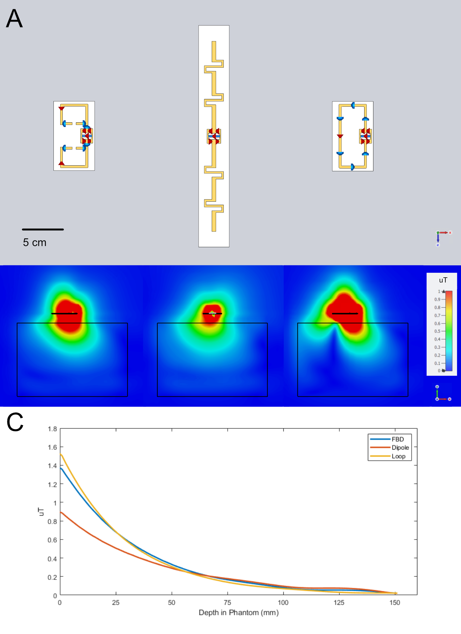
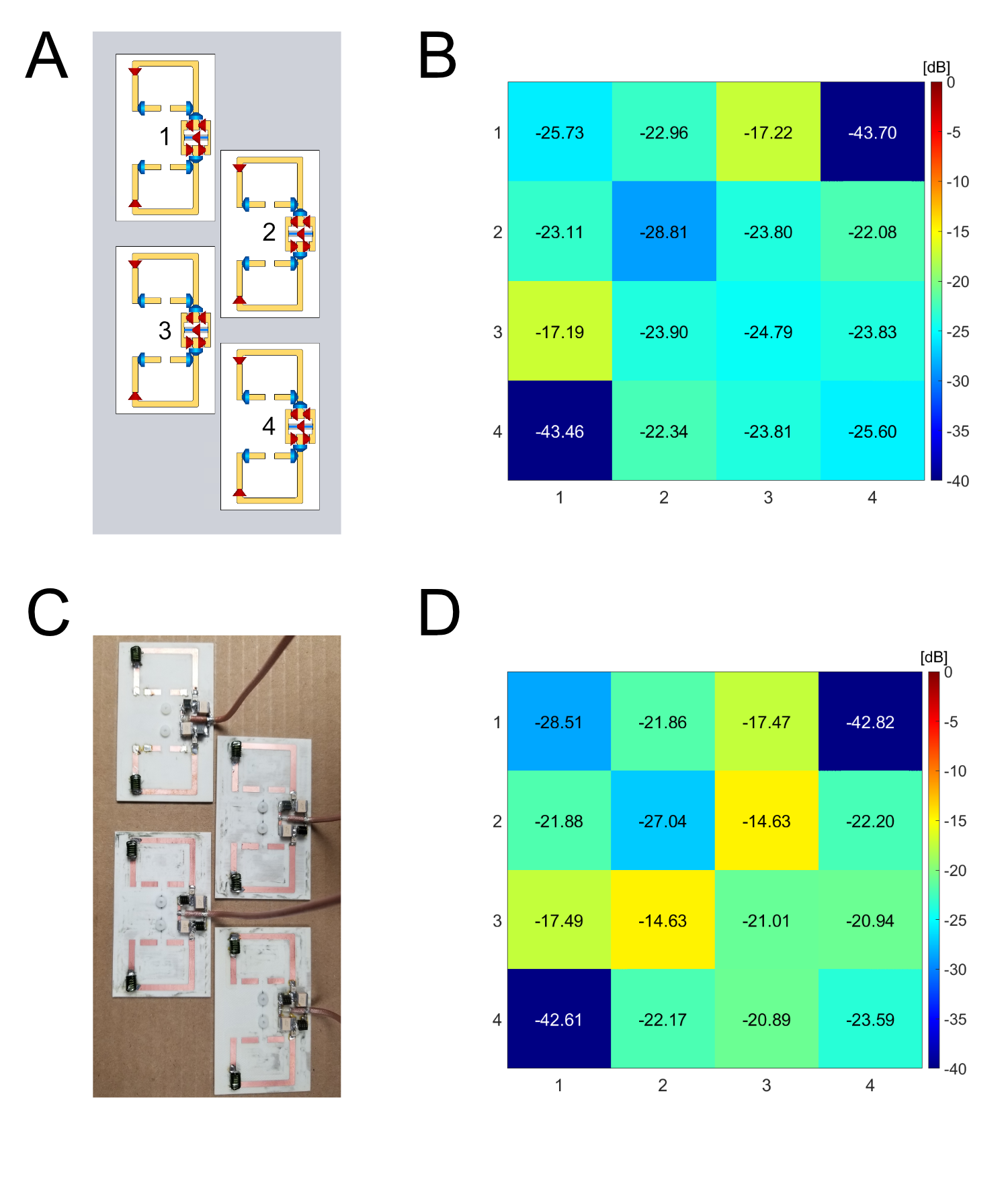
The DBD consisted of a dipole with two 90o bends in each leg, resulting in three segments (Figure 1a). An additional set of traces, each flanked with a series RF choke, was then used to create a complete DC path on each leg of the dipole. This enabled two B0 shimming elements per RF element, while only requiring two chokes per DC loop compared to the five or more chokes that would conventionally be required (see Figure 1). Matching was achieved using a lattice network, with series 1000 pF capacitors on either side to prevent DC back flow. Finally, series inductors placed between the second and third segments were used to electrically lengthen the element to achieve a resonant frequency of 447 MHz. The entire assembly was then placed on a 1.52 mm Rogers RO4003C substrate.The RF performance of the DBD was simulated in CST Microwave Studio 2020 with elements displaced 2 cm from the surface of a uniform loading phantom (εr = 45, σ = 0.61 S/m). The B1+ performance of the DBD was compared to a side-fed, size-matched loop (3.5 cm x 8 cm) and a fractionated dipole12, examining the RMS B1+ magnitude (normalized to 1 watt accepted power) vs depth through a volume of 4 x 4 cm cross-sectional area and centered under the feed point of each element (Figure 2). Additionally, a set of four DBDs in a staggered configuration was modeled to evaluate its decoupling performance. A four-DBD sub-array was then manufactured using the same parameters as simulation and assembled with all simulated components except for RF chokes. The elements were then arranged in the same staggered configuration to validate the simulation results of the decoupling performance (Figure 3). Bench measurements were conducted using a Rohde & Schwarz ZNBT vector network analyzer.
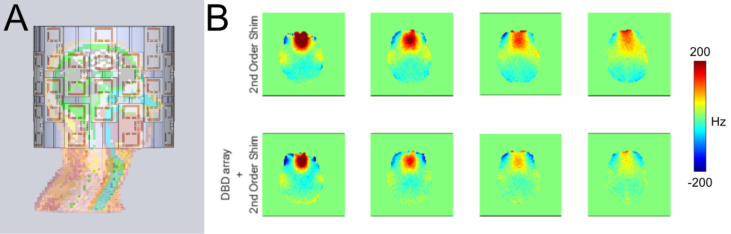
Finally, a full head-sized 32-channel transmit/64-channel B0 array (Figure 4) was modeled. The array was arranged in a 4 x 8 staggered-row configuration. The B0 shimming capabilities were simulated in Matlab 2020 using a Biot Savart solver13.
Results
The DBD displayed superior B1+ performance when compared to a fractionated dipole, yielding a 44% increase in surface B1+. Furthermore, the DBD B1+ performance was comparable to that of a size-matched loop, with a slight surface advantage for the loop and a slight depth advantage for the DBD (Figure 2). Using a staggered four-element configuration with close element spacing (~ 2 cm edge-to-edge), a DBD sub-array showed excellent inherent decoupling performance without the requirement for overlap or active decoupling components, demonstrating a worst-case -17.9 dB between vertically neighboring elements (Figure 3). Bench measurements, using similar loading conditions to simulation, showed reasonable agreement with simulation, validating the simulated tuning, matching, and decoupling properties. Initial B0 shimming simulations of the proposed array suggest that the 64 B0 shimming elements, used with a slice-optimized shimming solution in combination with the scanner’s 2nd order shims, yielded a 47% reduction in field offset in a 20x20 voxel frontal lobe ROI (Figure 4b) when compared to 2nd order shimming alone.Discussion and Conclusions
We have demonstrated a new “Double Bent Dipole” geometry for combined RF/B0 shimming. This element shows excellent decoupling and B1+ performance, making it a strong candidate for high-density parallel transmit arrays. Furthermore, a hypothetical head-sized array configuration demonstrates excellent B0 shimming performance. Thus, the DBD represents an ideal foundational element for combined RF/B0 shimming in high and ultra-high field applications.Acknowledgements
The authors would like to acknowledge research support from NIH U01 EB025144, NIH P41 EB027061, and NIH R01 EB025131.References
1. Stockmann JP, Witzel T, Blau JN, et al. Combined shim-RF array for highly efficient shimming of the brain at 7 Tesla. In: Proc. Int. Soc. Magn. Reson. Med. Vol 21. ; 2013:21.
2. Han H, Song AW, Truong TK. Integrated parallel reception, excitation, and shimming (iPRES). Magn Reson Med. 2013;70(1):241-247. doi:10.1002/mrm.24766
3. Darnell D, Truong TK, Song AW. Integrated parallel reception, excitation, and shimming (iPRES) with multiple shim loops per radio-frequency coil element for improved B0shimming. Magn Reson Med. 2017;77(5):2077-2086. doi:10.1002/mrm.26267
4. Stockmann JP, Witzel T, Keil B, et al. A 32-channel combined RF and B0shim array for 3T brain imaging. Magn Reson Med. 2016;75(1):441-451. doi:10.1002/mrm.25587
5. Raaijmakers AJE, Ipek O, Klomp DWJ, et al. Design of a radiative surface coil array element at 7 T: The single-side adapted dipole antenna: Design of a Radiative Coil Array Element at 7 T. Magn Reson Med. 2011;66(5):1488-1497. doi:10.1002/mrm.22886
6. Raaijmakers AJE, Italiaander M, Voogt IJ, et al. The fractionated dipole antenna: A new antenna for body imaging at 7. Magn Reson Med. 2016;75(3):1366-1374. doi:10.1002/mrm.25596
7. Duan Q, Nair G, Gudino N, et al. A 7T spine array based on electric dipole transmitters: 7T Spine Array Based on Electric Dipole Transmitters. Magn Reson Med. 2015;74(4):1189-1197. doi:10.1002/mrm.25817
8. Oezerdem C, Winter L, Graessl A, et al. 16-channel bow tie antenna transceiver array for cardiac MR at 7.0 tesla: 16-Channel Bow Tie Antenna Transceiver Coil Array for CMR. Magn Reson Med. 2016;75(6):2553-2565. doi:10.1002/mrm.25840
9. Avdievich NI, Solomakha G, Ruhm L, Bause J, Scheffler K, Henning A. Bent folded‐end dipole head array for ultrahigh‐field MRI turns “dielectric resonance” from an enemy to a friend. Magn Reson Med. 2020;84(6):3453-3467. doi:10.1002/mrm.28336
10. Avdievich NI, Solomakha G, Ruhm L, Scheffler K, Henning A. Decoupling of folded‐end dipole antenna elements of a 9.4 T human head array using an RF shield. NMR Biomed. 2020;33(9). doi:10.1002/nbm.4351
11. Avdievich NI, Solomakha G, Ruhm L, Henning A, Scheffler K. Unshielded bent folded‐end dipole 9.4 T human head transceiver array decoupled using modified passive dipoles. Magn Reson Med. 2021;86(1):581-597. doi:10.1002/mrm.28711
12. Ertürk MA, Wu X, Eryaman Y, et al. Toward imaging the body at 10.5 tesla. Magn Reson Med. 2017;77(1):434-443. doi:10.1002/mrm.26487
13. Quéval L. BSmag Toolbox User Manual.; 2015. Available: http://www.lqueval.com [Accessed April. 07, 2015].
Figures