0708
A novel 16-channel transmitter/32-channel receiver combined sleeve antenna and dipole array for the human whole brain imaging at 10.5 Tesla1Center for Magnetic Resonance Research, Minneapolis, MN, United States, 2Department of Electrical and Computer Engineering, Seoul National University, Seoul, Korea, Republic of
Synopsis
For whole brain human head imaging at 10.5 Tesla, we interlaced a 16-channel sleeve antenna transceiver with a 16-channel asymmetric dipole antenna receiver for a combined, close fitting 16-channel transmit/32 -channel receiver array. Integration of high dielectric constant material (HDC) significantly improved receiver performance in the upper brain. Simulation results indicate excellent B1 efficiency and coverage of the combined array for the whole brain imaging at 447 MHz. To further improve array performance, we developed new on-coil transmit/receive (T/R) switches capable of preamplifier decoupling. We are now in the process of building this novel closefitting 32-channel array.
Introduction
Clear signal-to-noise ratio (SNR) gains in magnetic resonance imaging (MRI) applications associated with ultra-high fields (UHF) have been predicted and experimentally demonstrated [1-3]. At UHF, higher channel count receiver arrays are essential and particularly beneficial for peripheral SNR and optimal parallel imaging performance [4, 5]. Radiative type antennas have been suggested for UHF head and body imaging and have shown better SNR for deep brain structures [6-10]. However, these radiative antenna arrays face greater challenges than their loop-type counterparts, such as minimizing coupling between neighboring elements and coupling due to coaxial cable routing [11, 12]. For an improved, high channel count radiative antenna array concept that reduces coaxial cable interactions and allows for higher arrays density, we have in a recent study [13], incorporated floating cable traps [14] into a monopole type antenna feed structure and developed a sleeve antenna array concept at 10.5 tesla (T) [15-18]. Here, we take this a step further and combine the sleeve antenna design with a tightly formed 16-channel asymmetric bent dipole receiver array. We also incorporate a high dielectric constant material (HDC) disk for potentially improved field pattern [19, 20], specific absorption rate (SAR), and transmit efficiency. Transmit and receive performance of this combined 16-transmitter (Tx) /32-receiver (Rx) array with and without HDC was evaluated in electromagnetic (EM) simulations. Furthermore, to improve receiver array isolation we designed and evaluated an on-coil transmit and receive (T/R) switch with an integrated low input-impedance preamplifier.Methods
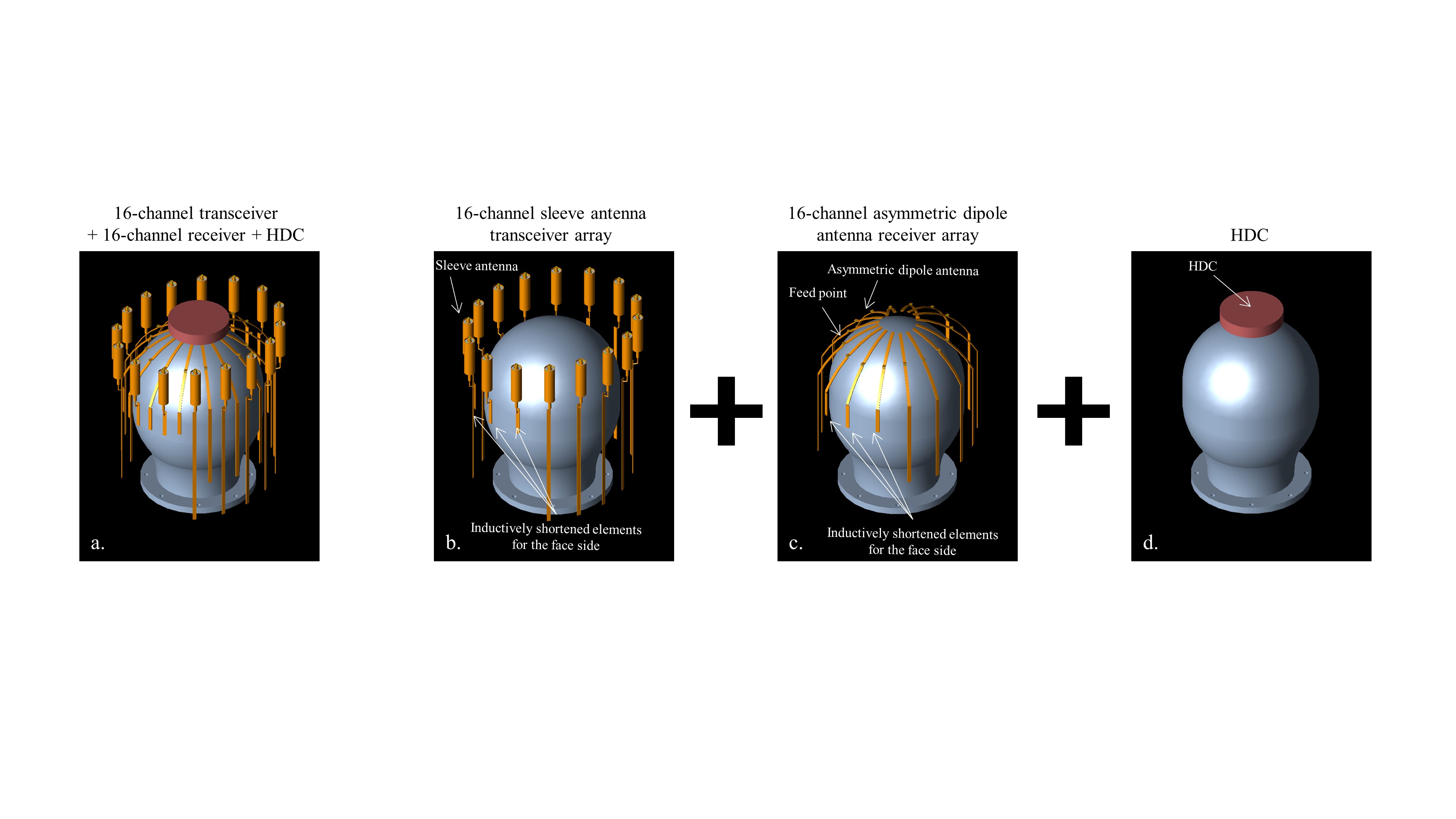
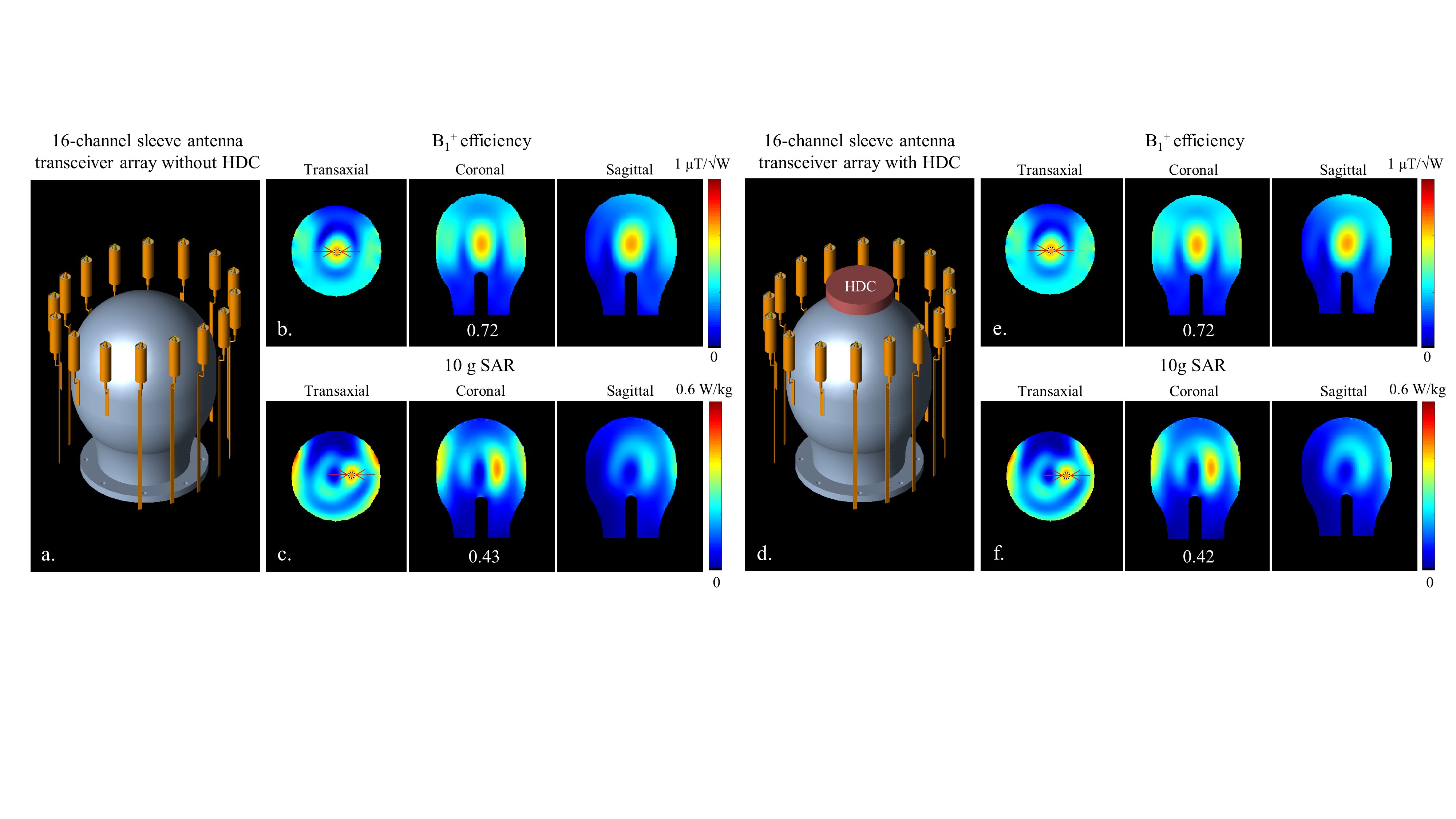
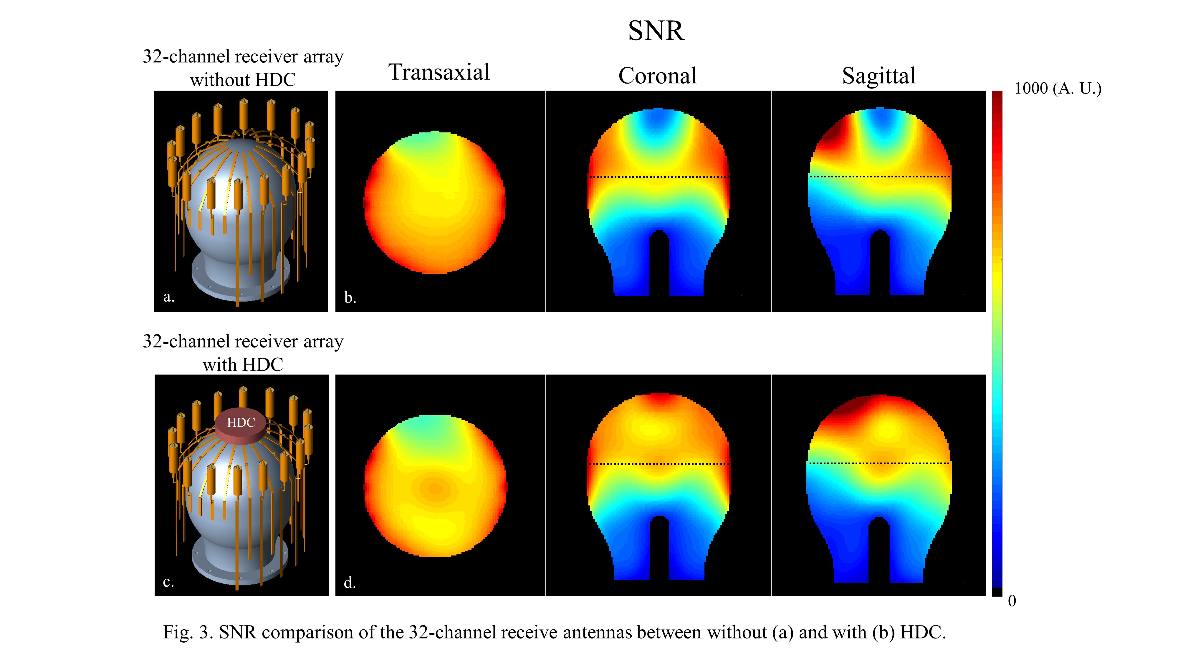
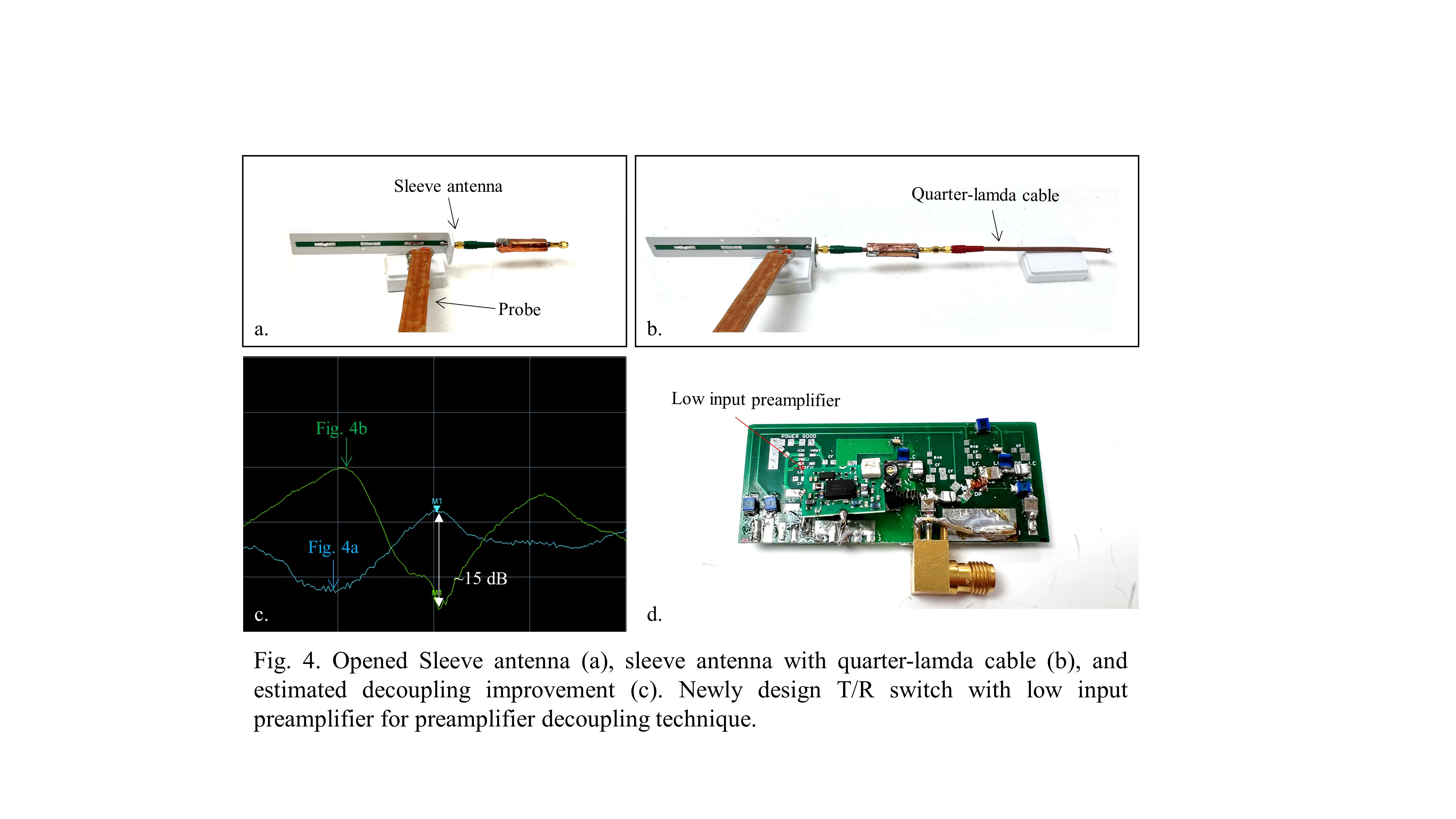
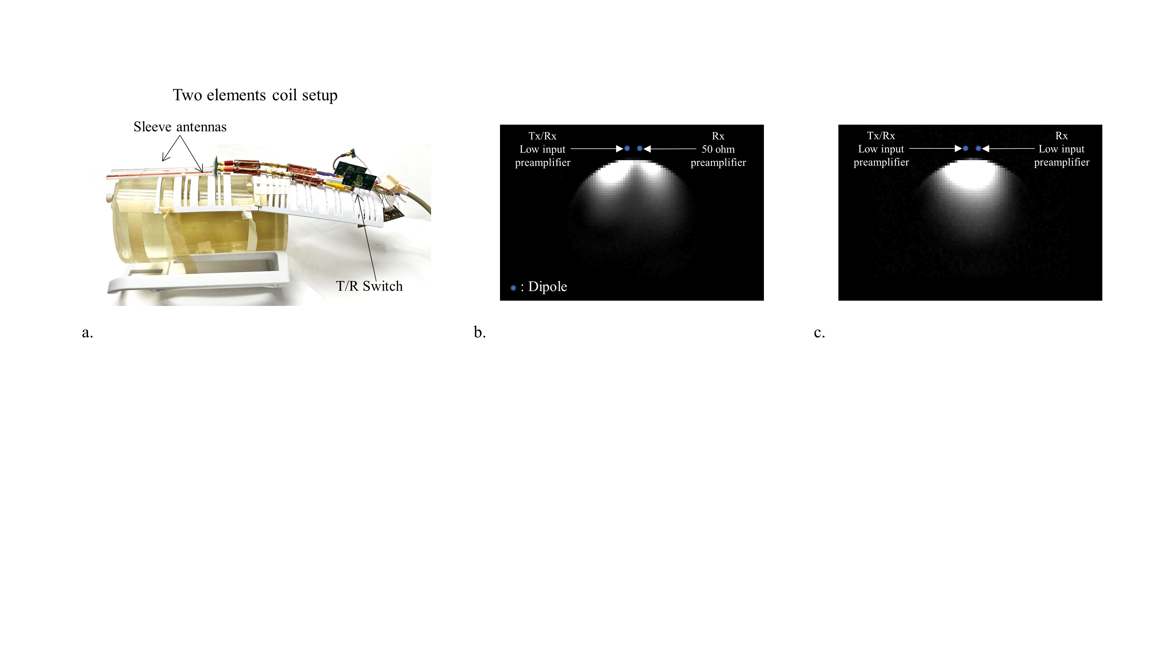
EM simulations (XFdtd; REMCOM, State College, PA) were performed and Matlab (Mathworks, Inc., Natick, MA, USA) was used to calculate the normalized B1+ efficiency, SAR efficiency, and SNR of a novel 16-Tx/32-Rx array (Fig. 1a) at 447 MHz (10.5 T). The proposed array combines a 16-channel sleeve antenna transceiver (Fig. 1b) built 19 cm by 22.6 cm elliptical cylindrical with a tight fitting 16-channel asymmetric bent dipole receiver (Fig. 1c) and incorporates a HDC disk (Fig. 1d) of 8.2 cm diameter and 1.6 cm thickness (σ= 0.0031 S/m and εr = 100). For subject comfort and to allow task presentation the coil is designed open-faced with three inductor (475 nH) shortened 5 cm sleeve antennas and three shorter asymmetric dipole elements positioned over the forehead. The other thirteen 20 cm long sleeve antenna elements each incorporate a 5 cm floating sleeve. As shown in Fig. 1c., the positioning of an HDC disc allowed the reduction of the length of the dipoles upper leg, leading to an overall asymmetric bent dipole design. To evaluate the effects of the HDC material, we compared the transmitter performance first with respect to B1+ efficiency (Fig. 2b and 2e) and 10 g SAR (Fig. 2c and 2f) of the 16-channel sleeve antennas without (Fig. 2a) and with (Fig. 2d) the HDC disk placed on the top of the sample. For the receivers, we evaluated the 32-channel (16 sleeve antenna elements and 16 asymmetric dipole antenna elements) receiver performance without (Fig. 3a and 3b) and with (Fig. 3c and 3d) the HDC disk. In order to improve decoupling between elements further, we designed a new on-coil T/R switch. Fig. 4 summarizes the build and performance of the new on-coil T/R switch with integrated low impedance preamplifier. We evaluated decoupling performance with a sleeve antenna in open (Fig. 4a) and with quarter-lamda transforming (Fig. 4b) preamplifier decoupling technique. The newly designed T/R switch with a low input-impedance preamplifier (WantCom, WMA447D, Minneapolis, MN) is shown in Fig. 4d. All imaging experiments were performed using a whole-body 10.5 T MRI system (Siemens Healthineers, Erlangen, Germany). Fig. 5 shows the experimentally acquired fully relaxed gradient echo images of two sleeve antennas with 50 ohm (Fig. 5a) vs. preamplifier decoupled (Fig. 5b) T/R switches.Results and Discussion
In simulation, we observed similar B1+ efficiency for the sleeve transceiver without and with the small HDC disk. (see Fig. 2b and Fig. 2e.). A similar and negligible impact on 10 g SAR maps without (Fig. 2c) and with (Fig. 2f) the HDC disk is observed. However, SNR comparison including the bent dipole receiver (Fig. 3b and Fig. 3d) clearly show more uniform SNR distribution in the entire phantom achievable with the HDC material present. As shown in Fig. 4c, an extra 15 dB improvement of preamplifier decoupling was established, and a clearly improved distribution was observed with the low input/low input-impedance preamplifier (Fig. 5b) T/R switch compared to the low input/50 ohm (Fig. 5a) preamplifier T/R switch allowing for sleeve antennas to be separated by only 3 cm close sleeve antennas. The newly proposed tight-fitting array coil for human brain imaging at 10.5 T supports a densely spaced combination of a 16-channel sleeve antenna transceiver with a formfitting 16-channel asymmetric dipole antenna array, for a combined 16-Tx/32-Rx whole head array at 10.5T. Simulation results indicate that excellent brain coverage is achievable, and that incorporation of HDC materials significantly improves the SNR in the upper brain region. We are currently building this array and will incorporate 16 elements of the newly designed preamplifier decoupling capable on-coil T/R switch for further performance gains.Acknowledgements
NIH U01 EB025144, NIH P41 EB015894, NIH S10 RR029672, and NRF 2021R1A2B5B03002783 and the BK21 FOUR program of the Education and Research Program for Future ICT Pioneers (A0426-20210100)References
[1] B. Guerin et al., "The ultimate signal‐to‐noise ratio in realistic body models," Magn Reson Med, vol. 78, no. 5, pp. 1969-1980, 2017.
[2] K. Ugurbil, "Imaging at ultrahigh magnetic fields: History, challenges, and solutions," , Neuroimage, vol. 168, pp. 7-32, 2018.
[3] J. T. Vaughan et al. , "7T vs. 4T: RF power, homogeneity, and signal-to-noise comparison in head images," Magn Reson Med, vol. 46, no. 1, pp. 24-30, 2001.
[4] F. Wiesinger, PF. Van de Moortele, G. Adriany, N. De Zanche, K. Ugurbil, and K. P. Pruessmann, "Parallel imaging performance as a function of field strength—an experimental investigation using electrodynamic scaling," Magn Reson Med, vol. 52, no. 5, pp. 953-964, 2004.
[5] F. Wiesinger, PF. Van de Moortele, G. Adriany, N. De Zanche, K. Ugurbil, and K. P. Pruessmann, "Potential and feasibility of parallel MRI at high field," NMR in Biomedicine, vol. 19, no. 3, pp. 368-378, 2006.
[6] N. Avdievich, G. Solomakha, L. Ruhm, J. Bause, K. Scheffler, and A. Henning, "Bent folded‐end dipole head array for ultrahigh‐field MRI turns “dielectric resonance” from an enemy to a friend," Magn Reson Med, vol. 84, no. 6, pp. 3453-3467, 2020.
[7] N. I. Avdievich, G. Solomakha, L. Ruhm, K. Scheffler, and A. Henning, "Evaluation of short folded dipole antennas as receive elements of ultra‐high‐field human head array," Magn Reson Med, vol. 82, no. 2, pp. 811-824, 2019.
[8] A. Raaijmakers et al., "Design of a radiative surface coil array element at 7 T: the single‐side adapted dipole antenna," Magn Reson Med, vol. 66, no. 5, pp. 1488-1497, 2011.
[9] G. C. Wiggins, B. Zhang, R. Lattanzi, G. Chen, and D. Sodickson, "The electric dipole array: an attempt to match the ideal current pattern for central SNR at 7 Tesla," presented at the Proc. 20th Annual Meeting ISMRM, Melbourne, Australia, 2012.
[10] M. Woo et al., "Extended Monopole antenna Array with individual Shield (EMAS) coil: An improved monopole antenna design for brain imaging at 7 tesla MRI,", Magn Reson Med, vol. 75, no. 6, pp. 2566-72, 2016.
[11] D. Hill and J. Wait, "Coupling between a Radiating Coaxial Cable and a Dipole Antenna,", IEEE Trans Communications, vol. 23, no. 11, pp. 1354-1357, 1975.
[12] B. Zhang et al., "29-channel receive-only dense dipole head array for 7T MRI," presented at the in Proc. Annual Meeting 2017 ICEAA, 2017.
[13] M. Woo et. al., "Comparison of 16-channel asymmetric sleeve antenna and dipole antenna transceiver arrays at 10.5 Tesla MRI," IEEE Trans Med Imaging, vol. 40, no. 4, pp. 1147 - 1156, 2020.
[14] D. A. Seeber, I. Jevtic, and A. Menon, "Floating shield current suppression trap,", Concept Magn Reson B, vol. 21b, no. 1, pp. 26-31, 2004.
[15] R. King, "Asymmetrically Driven Antennas and the Sleeve Dipole,", Proceedings of the Institute of Radio Engineers, vol. 38, no. 10, pp. 1154-1164, 1950.
[16] W. Kissick, WJ. Ingram, J. Vanderau, and R. Jennings, "Antenna System Guide NIJ Guide 202–00," NCJ, vol. 20531, 2001.
[17] W. L. Stutzman and G. A. Thiele, Antenna theory and design. John Wiley & Sons, 2012.
[18] W. L. Weeks, Antenna engineering. McGraw-Hill, 1968.
[19] M. Woo, L. DelaBarre, R. Lagore , S. Jungst, Q. X. Yang, B. Zhang, S. Rupprecht, R. Lattanzi, M. T. Lanagan, M. Sarkarat, K. Ugurbil, and G. Adriany, "Improved B1+ efficiency of a dipole antenna equipped with high dielectric constant (HDC) materials at 10.5T," Proc. ISMRM, p. 7431, 2019.
[20] M. Woo, L. DelaBarre, R. Lagore, S. Jungst, M. T Lanagan, T. Bonnett, Q. X. Yang, R. Lattanzi, K. Ugurbil, and G. Adriany, "A dipole antenna array with “flipped” high dielectric constant (HDC) material for improved SNR at 10.5 tesla," Proc. ISMRM, p. 1422, 2021.
Figures