0707
A Compact 16Tx-32Rx Geometrically Decoupled Phased Array for 11.7T MRI1CEA, IRFU, Université Paris-Saclay, Gif sur Yvette, France, 2Université Paris-Saclay, CEA, CNRS, BAOBAB, NeuroSpin, Gif sur Yvette, France, 3Multiwave Imaging SAS, Marseille, France
Synopsis
A geometrically decoupled 16Tx-32Rx RF coil has been designed for the Iseult 11.7T project. It has 16 transceive resonators and 16 receive-only loops. This peculiar architecture satisfied three major concerns: compactness-made compatibility with a local B0 shim insert, easy tuning and performance prediction. Simulations show high flip angle homogeneity in the whole brain (NRMSE<6%) with kT-points, accounting for all constraints (pulse length, SAR, power budget). Predicted global SNR in phantom with SoS reconstruction is 2.47±0.2 times higher as compared to 7T (with the commercial 8Tx-32Rx Nova coil) or equivalently, the SNR scales as B0 to the power of 1.74±0.16.
Introduction
An human brain RF coil has been designed for the Iseult 11.7T project. Its outer diameter is minimized (27 cm) to fit in a natural convection air-cooled local B0 shim device1. This requirement led to combine transceive elements with receive-only elements to cut through the total number of resonators providing finally a 16Tx-32Rx capability. RF coils generally consist in two separated arrays successively used for transmission and reception; the receive array being usually preamp-decoupled. At high frequency, preamp-decoupling becomes tricky because of parasitic inductances or capacitances of lumped components and impedance transformations of PCB traces. Consequently, the best trade-off between decoupling and SNR is difficult to find. In the current design, the capability of geometric decoupling is explored. It has also the advantage of providing an easy assessment of the coil performance.Methods
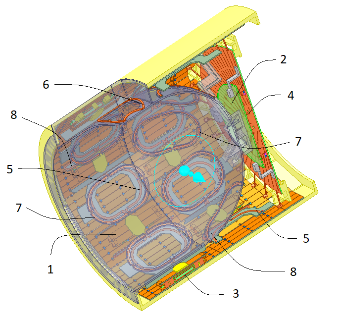
The transceive array is made of 15 linear resonators arranged in a lower and upper row in z-direction, hereafter referred to as dipoles, and 1 patch resonator, while the receive array consists in 16 loops (Figure 1). This configuration has already been used in 7T prototypes1,2. Here, the transceive resonators are fine-tuned by geometric deformation of conducting surfaces: strips (1) for dipoles and disk (2) for the patch resonator. Matching is achieved by optimizing the size of the coupling loop (3) and off-center position of the feeding connection (4) on the patch. Receive-only loops (5,6) are classically tuned and matched using three capacitors. Passive loops (7) resonating around 530 MHz ensure decoupling between dipoles according to the RID principle3. The patch resonator is intrinsically well decoupled from the others. In reception mode, bent extensions (8) on rectangular loops (5) provide decoupling from dipoles thanks to the Lenz's law as in RID3. The two oval loops (6) in front of eyes are overlapped to get decoupled.The design process makes use of Ansys Electronics Desktop (Pennsylvania, USA): simulations run on a dual-processor workstation (Intel 5122 CPU, 3.60 GHz, 768 GB RAM). Finite elements method simulations are supplemented by co-simulations to speed up all design steps. All relevant simulations results (scattering matrix, E and H fields) are exported for coil performance analysis. Simulations are carried out for two homemade anatomical models: a 16-tissue male model and a 10-tissue female model. A 16cm-diameter spherical agar phantom (er=72, s=0.8 S/m) is also used for global SNR prediction as compared to 7T.The current availability of only eight transmit channels in the project motivated the analysis of four configurations: 16CH, F2FH, SBS and SVD. The 16CH configuration has 16 independent channels while the others have only eight channels. In F2FH, two face-to-face dipoles with respect to the sagittal plane are paired with constructive field interference on that plane. In SBS3, two neighboring dipoles of the same row are paired with a phase shift corresponding to their relative azimuthal position. In those two configurations, one dipole is left for receive use only. Finally, SVD takes the first eight SVD modes4 as obtained from the female model brain.
In this design, all resonators are tuned and matched to 50 ohms, and 50-ohm input impedance preamplifiers are considered. Therefore, thermal SNR can be easily compared from one coil to another by the sum of squares of the B1- fields for one Watt incident power following the principle of reciprocity; the noise power being kTB. Here, the Rapid coil (8Tx-8Rx) is simulated and used as a reference since the CAD model of the Nova coil (8Tx-32Rx) is not available. A measurement of the SNR on an agar phantom bridged the gap and allowed a comparison to the Nova coil.
Results
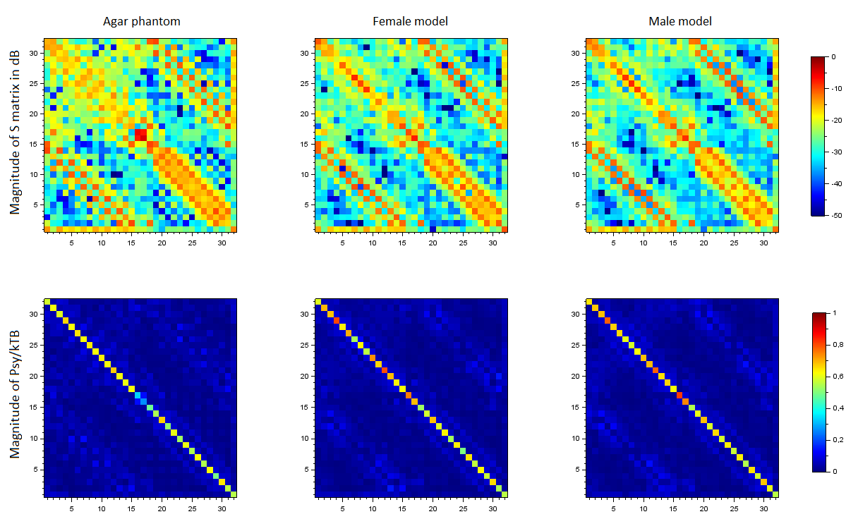
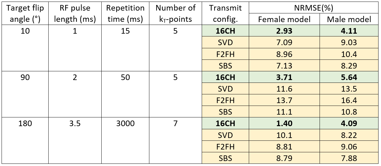
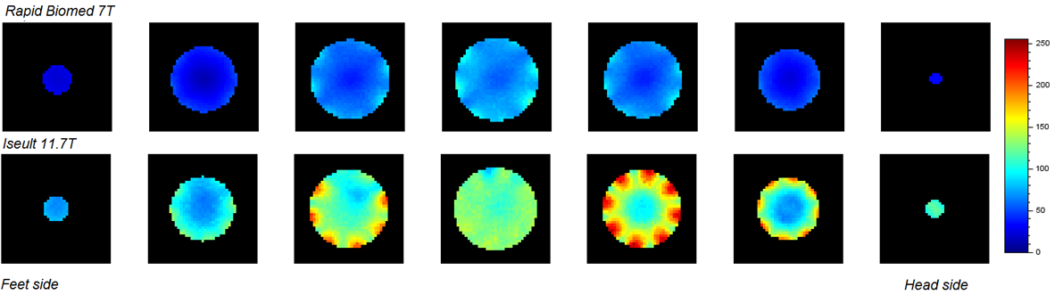
Figure 2 shows scattering and noise covariance matrices; the latter being predicted5,6 by $$$\Psi = kTB(I-SS^{H})$$$. Except the two oval loops, all mutual couplings are kept around -10 dB or below and noise correlation appears very acceptable. Transmit performance is shown in Figure 3. The kT-points simulations7 account for power budgets (peak<1.2 kW, average<5 W), as well as for local and global SAR constraints. As expected, 16 channels provide the best results; the other configurations being generally limited by the local SAR constraints.In reception, notwithstanding B0, it is possible to define a figure of merit: $$$S_{coil}=\sqrt{\sum_{k=1}^{N}\left | B_{1k}^{-} \right |^{2}}$$$ , where N is the number of channels. Figure 4 shows $$$S_{coil}$$$ in the agar phantom for our coil and the Rapid coil. Let S1 and S2 be their average values respectively; let M2 and M3 be the measured average SNR respectively for the Rapid and Nova coils. Simulations and measurements give respectively S1/S2 = 2.2 and M3/M2 = 2.5±0.2. Since signal scales as B02, the SNR gain from the Nova coil (7T) to our coil (11.7T) can be estimated by
$$\left[\left (\frac{S1}{S2}\right)/\left (\frac{M3}{M2}\right )\right]\left(\frac{11.7}{7}\right)^{2}=2.47\pm 0.2=\left(\frac{11.7}{7}\right)^{\alpha},$$
resulting in an $$$\alpha$$$ value of 1.74±0.16.
Conclusion
An alternative to preamp-decoupling is proposed for high frequency RF coils where transmit and receive performance can be easily simulated. Even though the electronic extra noise from the preamplifier is discarded in this model, its effect is expected negligible (<10% penalty) since nowadays preamplifiers can provide a noise figure as low as 0.6 dB. This approach was validated with a twin-prototype at 7T, named Avanti21.Acknowledgements
This work has been supported by the French Banque Publique d'Investissement (BPI), in the framework of the French-German Iseult/INUMAC project.References
1. Pinho Meneses B. Static Field Shimming in the Human Brain for UltraHigh Field MRI: Conceptual Limits and Development of a Novel Hardware Prototype. Ph D Thesis. Université Paris-Saclay, France, Orsay, 2021.
2. Georget E, et al. A Transmit-Array RF Coil with 12 Transmit Elements and 22 Receive Elements for an 8-Channel Parallel Transmission System at 7 T. ESMRMB Abstract, Berlin, 2015.
3. Avdievich N, et al. Resonant Inductive Decoupling (RID) for Transceiver Arrays to Compensate for both Reactive and Resistive Components of the Mutual Impedance. NMR Biomed; 26(11):1547-54, 2013.
4. Ferrand G, et al. SVD-based Hardware Concept to Drive N Transmit Elements of a Phased Array Coil with M≤N channels for High Field MRI, Proc. Intl. Soc. Mag. Reson. Med. 19, 2011.
5. Wedge S W. Noise Waves and Passive Linear Multiports. IEEE Microwave and Guided Wave Letters, Vol. 1, No. 5, 1991.
6. Findeklee C. Array Noise Matching via the Scattering Matrix. IEEE Transactions on Antennas and Propagation, Vol. 67, No. 4, 2019.
7. Cloos M A, et al. kT -points: Short Three-Dimensional Tailored RF Pulses for Flip-Angle Homogenization over an Extended Volume, Magn Reson Med, 67(1):72-80, 2012.
Figures