0646
Continuous Arterial Spin Labeling with On-Coil Amplification at 7T1NINDS/LFMI, National Institutes of Health, Bethesda, MD, United States, 2Department of Biomedical Engineering, Case Western Reserve University, Cleveland, OH, United States, 3NINDS/NMRF, National Institutes of Health, Bethesda, MD, United States
Synopsis
Continuous arterial spin labeling using a separate neck labeling coil is an attractive approach for imaging perfusion at 7T. This approach is hindered by specialize hardware including a labeling coil and a separate amplifier located outside the magnet room. On-coil amplifiers have demonstrated higher RF power efficiency with minimal cable loss and patient-coil interaction. This work shows that a separate labeling coil using on-coil amplification can be used for flow driven adiabatic inversion in a flow phantom suggesting that it may provide a suitable approach to simplify the hardware package required as well as to improve CASL studies at 7T.
Introduction
Arterial spin labeling (ASL) perfusion MRI is commonly performed using the pseudo-continuous ASL technique at ≤ 3T 1. However, it is difficult to optimize this technique at 7T due to its sensitivity to field inhomogeneity and RF power requirements 2. Continuous ASL (CASL) using a separate neck labeling coil is an attractive approach to overcome these limitations. This approach has been demonstrated in animals 3,4, humans at 3T 5-9 and higher fields 10-12. In these studies, a separate amplifier was used to deliver the RF power to the neck labeling coil. Recently, on-coil current source switch-mode amplifiers have demonstrated higher RF power efficiency compared to conventional RF transmission at 7T 13,14. In addition, this technology is relatively insensitive to patient-coil interaction which could help to reduce the inter-subject variability of labeling efficiency 14. In this work, we show the feasibility of using a separate labeling coil integrating on-coil amplification in a flow phantom for CASL at 7T.Methods
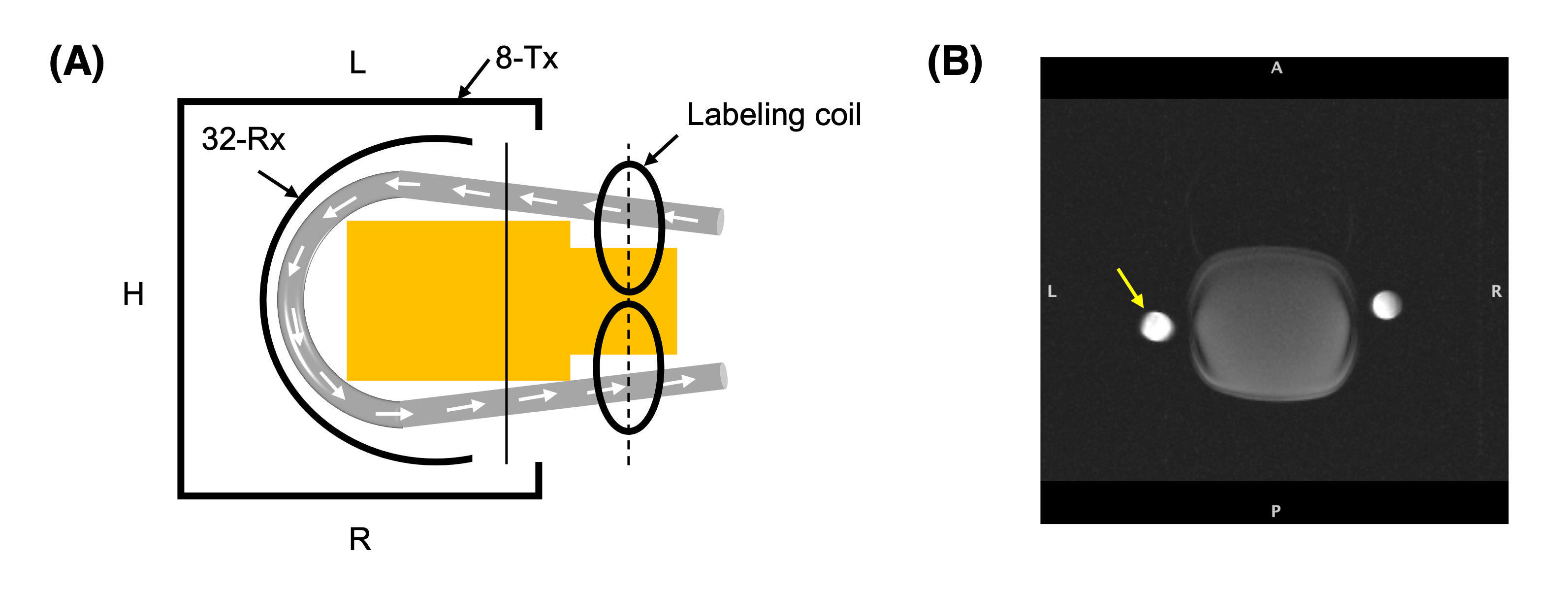
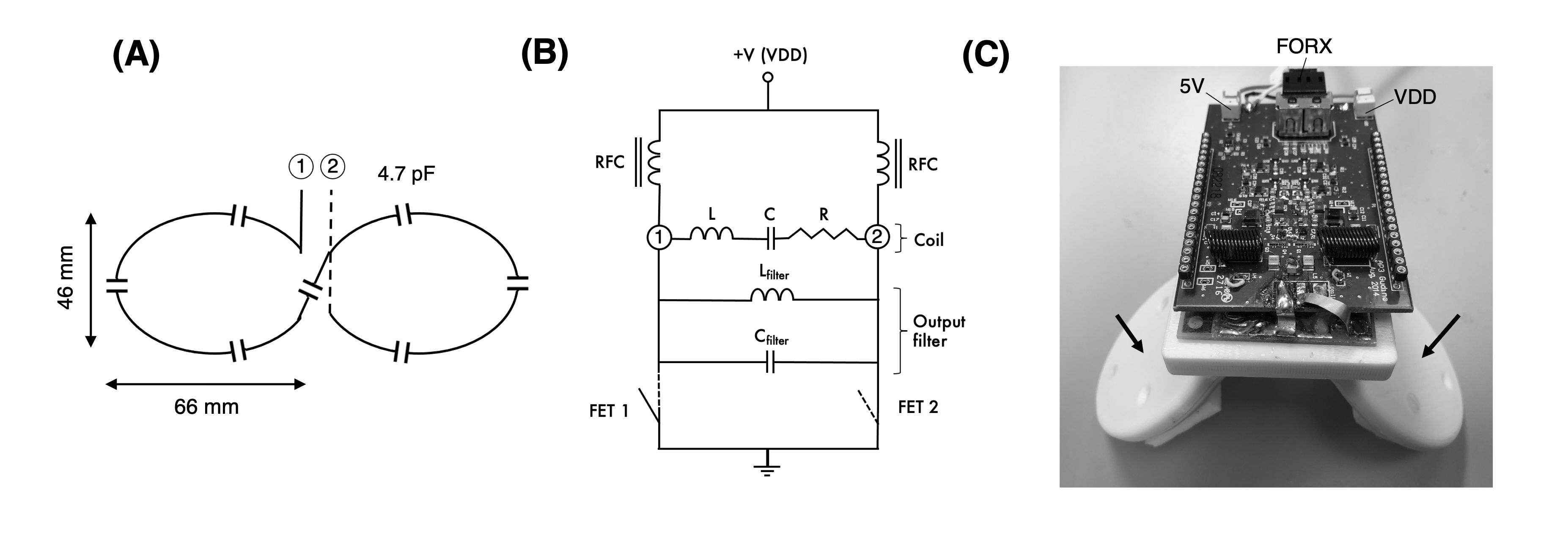
Experiments were conducted on 7T Magnetom Terra scanner (Siemens Healthineers, Germany) using an 8-Tx/32-Rx head array (Nova Medical, USA) operating in CP-mode. The flow phantom consisted of a MR-compatible flexible tube of 1.5 cm diameter filled with a water-glycerol based fluid mimicking blood properties. Flow was generated by a CardioFlow 5000 MR pump (Shelley Medical, Canada) with a constant flow rate of 100 mL/s. The flow velocity was measured with a phase contrast sequence using following parameters: axial, FOV=230x190mm2, matrix size=208x256, slice thickness=5mm, TR/TE=39.8/4.24ms, FA=15°, BW=543Hz/px, velocity encoding (VENC)=90cm/s (through plane), 5 averages, 10 measurements. The flow tube was placed inside the head array wrapped around a plastic bottle filled with oil. The labeling coil was positioned ~2 cm away from the tube outside the imaging coil (Figure 1).The labeling coil consisted of two elliptical surface loops (46 x 66 mm2) angled at 90° in Helmholtz configuration driven by an on-coil current mode class-D (CMCD) amplifier previously introduce for imaging at 7T 13 (Figure 2). Briefly, the CMCD stage consisted of two enhanced mode gallium nitride transistors (eGaN FETs) switching in push-pull configuration (Figure 2B) at the Larmor frequency. In this first experiment, the amplitude of a hard RF pulse was manually controlled by setting the drain voltage (VDD) of the CMCD stage. RF carrier was generated by a frequency synthesizer and converted to an optical signal (~297.2 MHz) before amplification. VDD and +5 V DC power line supplying the amplifier were connected through the penetration panel in the scanner cabinet room. RF and +5 V DC were triggered by a down TTL of 2.5 sec generated by the pulse sequence. A gradient of 3.5 mT/m was simultaneously applied during both control and labeling periods and no RF power was delivered during control. The RF carrier was adjusted to an offset frequency of 28.6 kHz corresponding to the labeling location at 19.2 cm from isocenter.
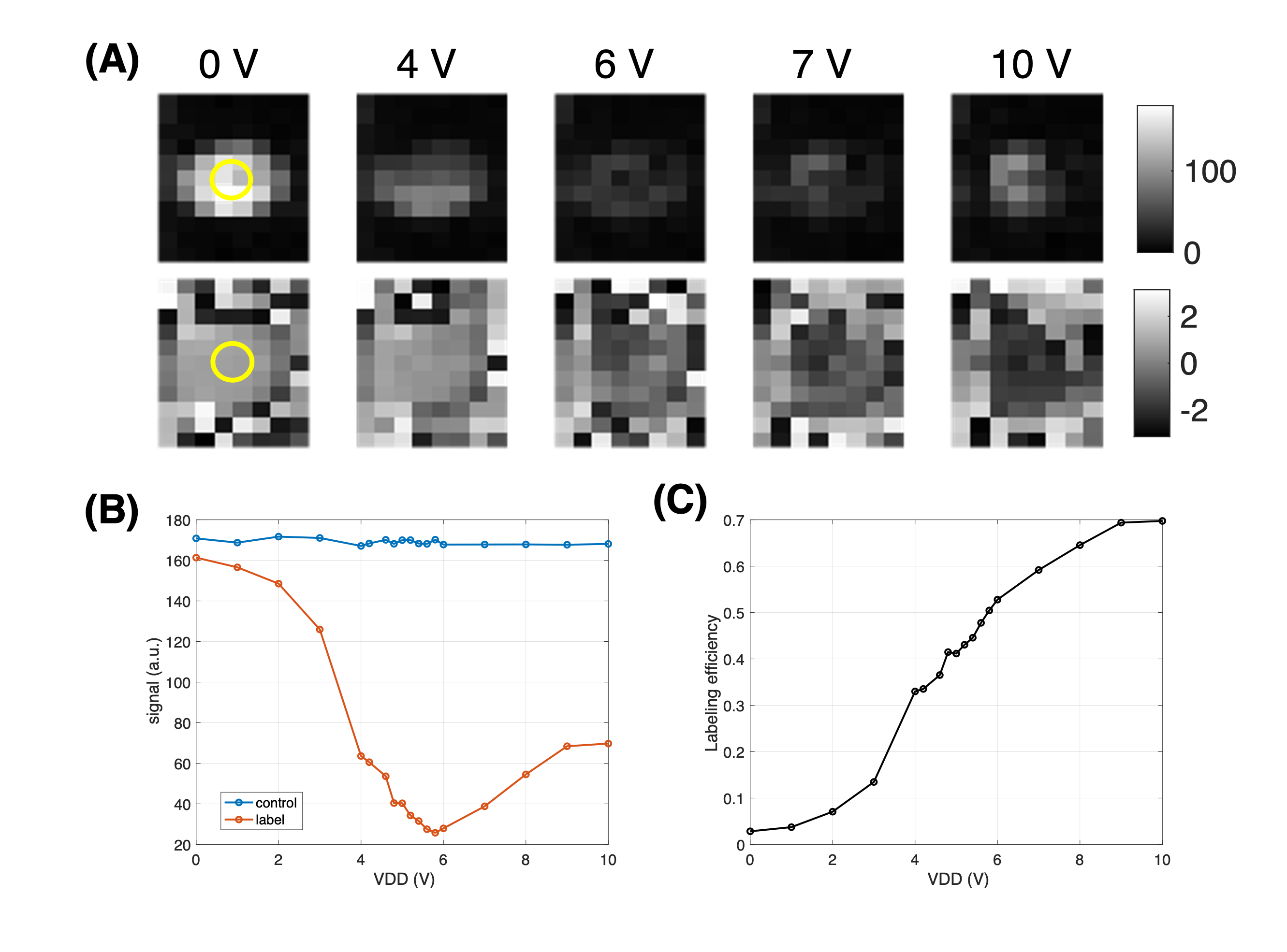
The labeling efficiency was measured 10 ms after 2.5 sec control and labeling periods using a modified turbo FLASH (CASL-TFL) sequence with following parameters: axial, matrix size=80x52, FOV=240x156mm2, slice thickness=3mm, TR/TE=4510/1.6ms, BW=490Hz/px, asymmetric echo=36%, echo spacing= 3.6ms, flip angle=5°, IPAT 2, turbo factor=52, total TFL read-out was acquired in centric ordering in 93.6 ms. The imaging slice was positioned 8 cm downstream from the labeling plane (Figure 1). Four pairs of label and control images were acquired alternatively in a total acquisition time of 36 sec. The difference of complex signal between control (Scontrol) and tag (Stag) images (ΔS) were averaged across measurements and used to calculate the labeling efficiency α=|ΔS|/(2*Scontrol). ASL images were acquired in random order at different VDD (0-10V) with a variable voltage step. Labeling efficiency was estimated in 4 pixels at the center of the cross section of the tube. Head coil receiver array was detuned during labeling using an interface box built in-house to avoid potential coupling effects.
Results
Flow velocity was measured to be ~48 ± 0.15 cm/s (mean ± standard deviation). Figure 3A shows measured magnitude and phase images of the label condition at selected VDD values. With increasing VDD, the magnitude signal goes through a minimum along with phase reversal indicating spin inversion at higher VDD. Figures 3B and C show the average signal for control/label images and the calculated labeling efficiency as a function of VDD, respectively. Maximum labeling efficiency was found to be 0.70 at 10 V without correcting for T1 recovery (Figure 3C).Discussion
This preliminary work shows that a neck labeling coil with on-coil amplification can be used for flow driven adiabatic inversion in a flow phantom at 7T. This novel labeling coil operated successfully together with all other hardware (Tx, Rx and detuning interface). A miniaturized version of a dedicated on-coil amplifier with current amplitude feedback is currently under development to improve RF monitoring and patient safety. Moreover, further tests will be conducted at higher power with coil load matching human head/neck properties. Finally, SAR simulations will be conducted to determine maximal current amplitude to limit RF power deposition in tissue.Conclusion
Separate neck labeling coil using on-coil current source amplification may provide a suitable approach for improved CASL studies at 7T.Acknowledgements
No acknowledgement found.References
1. Alsop DC, Detre JA, Golay X, et al. Recommended implementation of arterial spin-labeled perfusion MRI for clinical applications: A consensus of the ISMRM perfusion study group and the European consortium for ASL in dementia: Recommended Implementation of ASL for Clinical Applications. Magn. Reson. Med. 2015;73:102–116.
2. Teeuwisse WM, Webb AG, van Osch MJP. Arterial spin labeling at ultra-high field: All that glitters is not gold. Int. J. Imaging Syst. Technol. 2010;20:62–70.
3. Zhang X, Nagaoka T, Auerbach EJ, et al. Quantitative basal CBF and CBF fMRI of rhesus monkeys using three-coil continuous arterial spin labeling. NeuroImage 2007;34:1074–1083.
4. Silva AC, Zhang W, Williams DS, Koretsky AP. Multi-Slice MRI of Rat Brain Perfusion During Amphetamine Stimulation Using Arterial Spin Labeling. Magn. Reson. Med. 1995;33:209–214.
5. Zaharchuk G, Ledden PJ, Kwong KK, et al. Multislice perfusion and perfusion territory imaging in humans with separate label and image coils. Magn. Reson. Med. 1999;41:1093–1098.
6. Talagala SL, Ye FQ, Ledden PJ, et al. Whole-brain 3D perfusion MRI at 3.0 T using CASL with a separate labeling coil. Magn. Reson. Med. 2004;52:131–140.
7. Hetzer S, Mildner T, Driesel W, et al. Shielded dual-loop resonator for arterial spin labeling at the neck. J. Magn. Reson. Imaging 2009;29:1414–1424.
8. Mildner T, Trampel R, Möller HE, et al. Functional perfusion imaging using continuous arterial spin labeling with separate labeling and imaging coils at 3 T: Functional Perfusion Imaging. Magn. Reson. Med. 2003;49:791–795.
9. Hernandez-Garcia L, Lee GR, Vazquez AL, et al. Fast, pseudo-continuous arterial spin labeling for functional imaging using a two-coil system: Fast, Pseudo-Continuous ASL. Magn. Reson. Med. 2004;51:577–585.
10. Stafford RB, Woo M-K, Oh S-H, et al. An actively decoupled dual transceiver coil system for continuous ASL at 7 T: An Actively Decoupled Dual Transceiver Coil System. Int. J. Imaging Syst. Technol. 2016;26:106–115.
11. Mora Álvarez MG, Stobbe RW, Beaulieu C. High resolution continuous arterial spin labeling of human cerebral perfusion using a separate neck tagging RF coil Jiang Q, editor. PLOS ONE 2019;14:e0215998.
12. Chuang K-H, Merkle H, Chesnick S, et al. Continuous arterial spin labeling Perfusion MRI at 7T. In Proceedings of the 13th ISMRM. Miami, USA, 2005.
13. Gudino N, de Zwart JA, Duan Q, et al. Optically controlled on‐coil amplifier with RF monitoring feedback. Magn. Reson. Med. 2018;79:2833–2841.
14. Gudino N, Zwart JA, Duyn JH. Eight‐channel parallel transmit‐receive system for 7 T MRI with optically controlled and monitored on‐coil current‐mode RF amplifiers. Magn. Reson. Med. 2020;84:3494–3501.
Figures