0645
The TMSMR 28 channel RF coil: whole head imaging for the 3-axis TMS multichannel system1Martinos Center - MGH, Charlestown, MA, United States, 2Harvard Medical School, Boston, MA, United States, 3Institute of Medical Physics and Radiation Protection, Technische Hochschule Mittelhessen, Giessen, Germany
Synopsis
Multichannel Transcranial Magnetic Stimulation is an emerging technology for non-invasive stimulation of the human brain. Combining this technique with fMRI offers the unique benefits of studying the causal relationships between the cortical and subcortical nodes of large-scale brain networks. For this reason a whole head 28-channel RF coil array was developed to be integrated with the first 3-axis-TMS multichannel system. We have analyzed how the SNR of the constructed array changes when placing the stimulation units. Additionally, we compared the SNR/g-factor maps with commercial available 32/20-channel RF coils. The results show that the RF coil is performing as expected.
Introduction
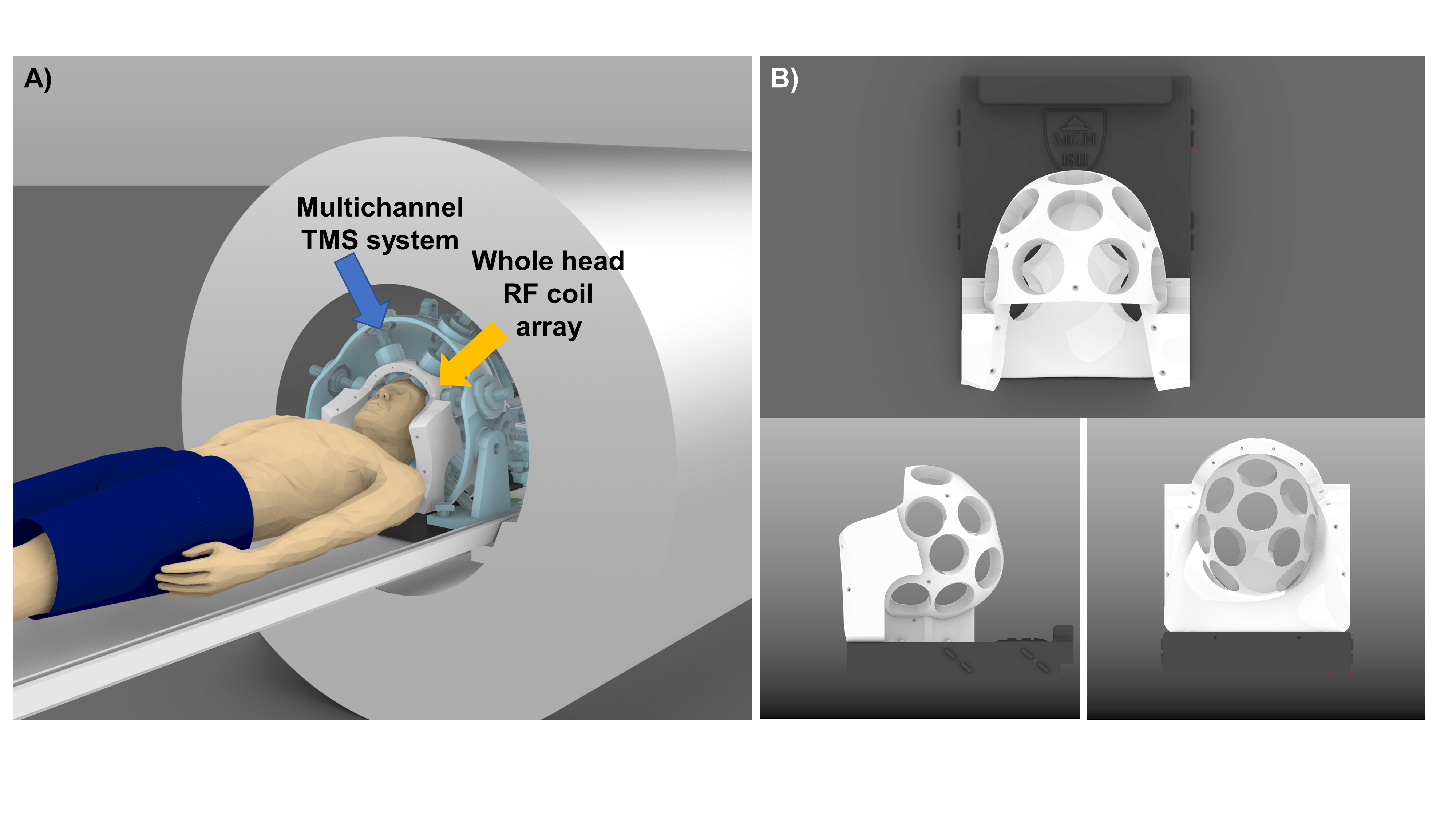
Multichannel Transcranial Magnetic Stimulation (mTMS) is an emerging technology for non-invasive stimulation of the human brain. The use of multiple TMS coils in an array configuration enables shifting the location TMS ‘hot spot’ electronically without any mechanical movement. This is achieved by computationally determining the current amplitudes to be passed to each of the coil elements to synthesize a desired target field pattern (1). There is an increasing interest in combining brain imaging methods with non-invasive brain stimulation as such approaches have the potential drastically improve the understanding of brain function in healthy and diseased stated. Combining non-invasive stimulation techniques such as TMS with fMRI offer the unique benefits of studying the causal relationships and functional connectivity between the nodes of large-scale brain networks. In particular, the mTMS technique would be become powerful when used in conjunction with functional MRI (fMRI), since maneuvering any TMS coil inside the scanner environment either manually or robotically is rather cumbersome. The basic combination of single-channel TMS and fMRI has been demonstrated (2), subsequently optimized in terms of TMS-compatible RF receive coil arrays (3) and proven to be safe (4). However, whole head coverage with high-density RF receive coil arrays is still lacking from TMS/MRI experimental settings. To enable combining mTMS with fMRI, we have designed, constructed and validated a whole head 28 channel RF coil array to be integrated with the first 3-axis TMS (5) multichannel system (see Figure1).Methods
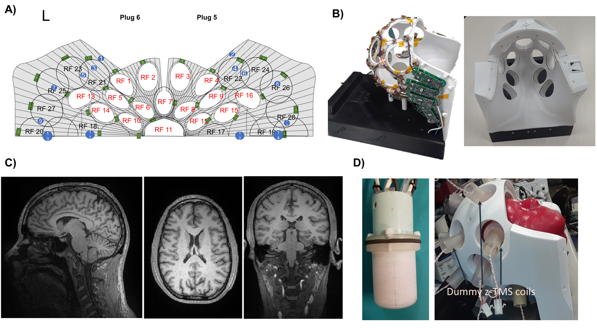
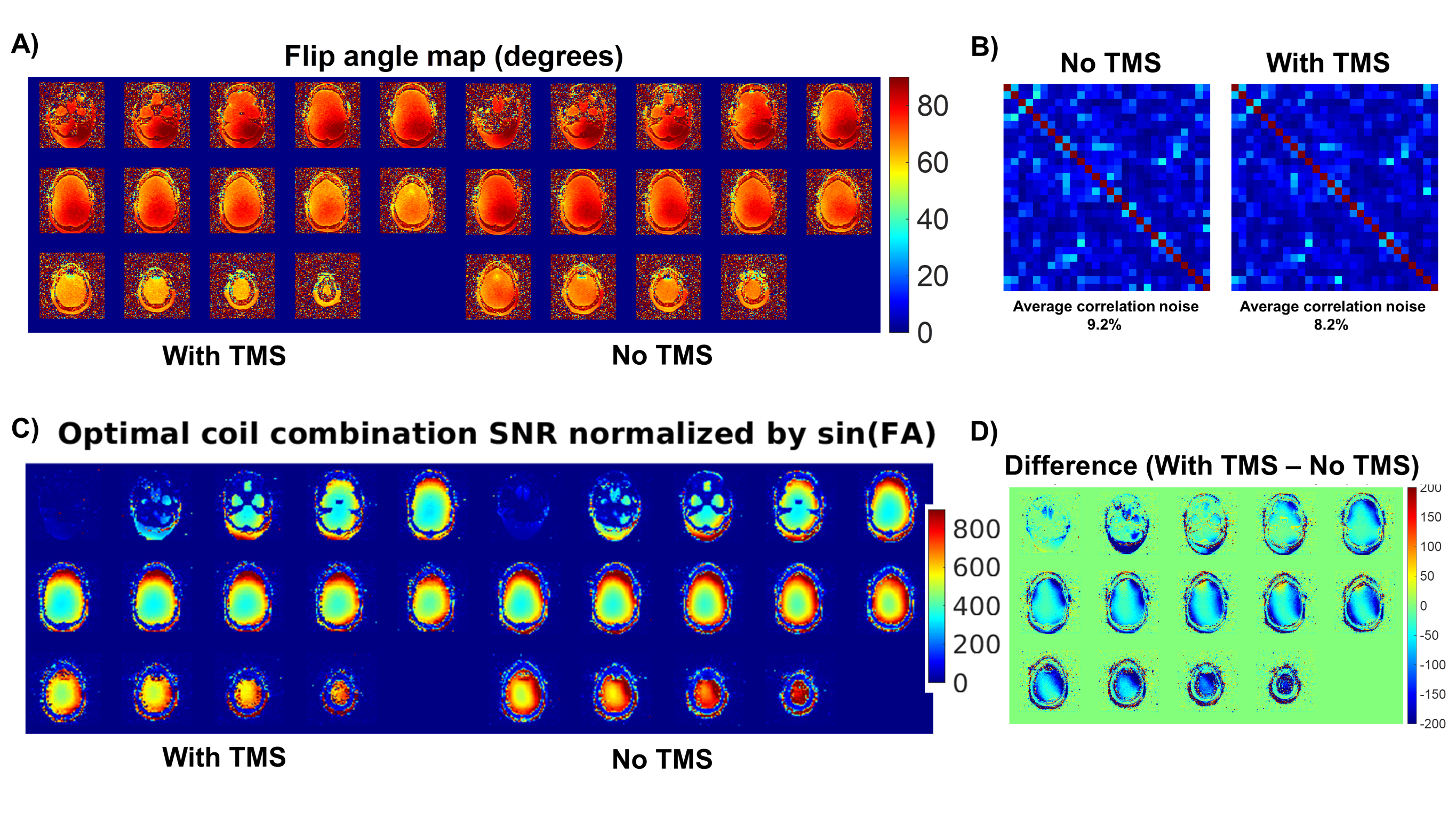
A whole head 28-channel RF coil array with 16 holes for the 3-axis TMS coils was designed, developed, and constructed for a 3T MRI system (Skyra, Siemens, Erlangen, Germany). The layout of the RF coil is shown in Figure2A. All elements were noise-matched to the Siemens Skyra/Prisma preamplifiers (50 ohm) and preamplifier decoupled using a second-order matching network. To isolate the receiver elements from transmission, an active detuning network was implemented in each loop, including a fuse as a safety final feature. Preamplifiers were moved slightly towards the sides and rear of the coil former. This facilitates an overall open coil topology for positioning the mTMS array (see Figure2B and an MR-compatible 3-axis TMS in Figure2D). Cable lengths connecting the RF coils to the preamplifiers were minimized and on the three longest cables (connecting RF element 6,7 and 8) small floating cable traps were attached to the cable to minimize common mode currents. The coaxial cables from the preamplifier outputs were brought to the base of the coil (in black) through holes, where the Siemens direct connect plug was placed and interfaced to the RF coil. The coil was covered with a housing to isolate all electronic components from the subject’s head. To validate the performance of the TMSMR 28-channel coil, we first compared the nominal SNR map of the coil when placing “dummy TMS coils” (to emulate the final setup using the 3-axis TMS coils, see Figure 2D for set up) with the nominal SNR of coil without any TMS elements. To calculate the nominal SNR, we acquired GRE images (2mm isotropic, FA90, 72 slices, MA 128x128, TE=2.6ms, TR=50ms, FA=90°) and flip angle maps (2mm isotropic, TE=2.56 TR-16880ms, MA=96x96, FA=8°) on a head phantom using the same voltage. The calculated SNR (6) were normalized with the sin(FA) to remove the B1+ effects produced by the mTMS system (4). Additionally, to compare the performance of the new constructed coil with commercial coils, we acquired in vivo images without any TMS coils using GRE (2mm isotropic, FA 90, 72 slices). SNR and g-maps data, obtained from in vivo images without any TMS elements, were compared to commercially available 32-channel and 20-channel head coils.Results
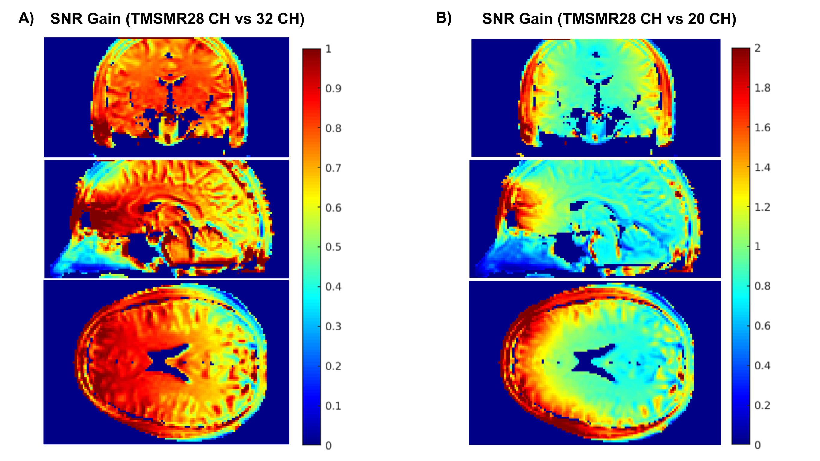
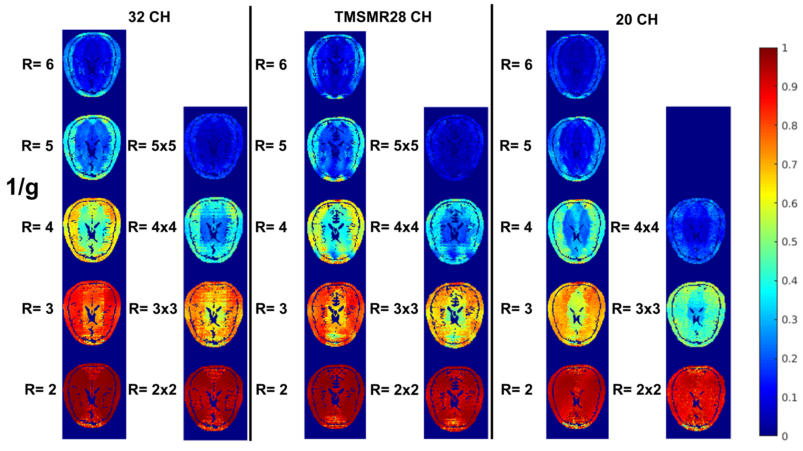
Figure3 shows the flip angle maps, noise correlation matrices and the normalized SNR maps for both cases: (i) with 16 “dummy TMS coils” on the head phantom and (ii) without them. Changes observed on the flip angle map are in the expected ranges (4). No significant changes were observed in the noise correlation matrix. Installing the dummy TMS coils caused locally an SNR decrease of up to 25% mainly at the edge of the phantom. Figure4 presents the SNR comparison of the TMSMR 28-channel coil with the commercial 32- channel and the 20-channel head coils. The average SNR gain of the TMSMR 28-channel coil from the representative sagittal, coronal, and transverse slices was measured to be 1.0/1.63, 0.87/1.3, and 0.77/1.26, respectively, when compared with the 32/20-channel head coils. G-factors for each of the three coils are shown in Figure5.Discussion
Initial results of the imaging performance of a constructed TMSMR 28-channel coil are presented. When TMS coils (dummy) were present, an SNR degradation of the receive array could be observed. This is likely attributed to copper shading effects due to eddy current induced losses and susceptibility effects of the TMS elements close to surface of the phantom. The SNR obtained from the TMSMR 28-channel coil was similar to that of the commercial 32-channel coil. When compared to the 20-channel coil an SNR improvement was achieved. The measured g-factors were also comparable to the stand 32-channel head coil favoring the use of advanced acceleration techniques for future combined TMS/fMRI neuroimaging studies.Acknowledgements
This work was funded by NIH R00EB015445, R01MH111829, NIH R00EB021349 and the Rappaport Foundation. We also want to thank Jon Polimeni for sharing his scripts for the calculation of SNR maps and g-factor maps.References
(1) Ruohonen J and Ilmoniemi R. Medical and Biological Engineering and Computing, Vol. 36 p297-301,1998
(2) Bohning et al., Invest Radiol,33(6):336-340,1998
(3) Navarro de Lara et al., MRM, 74(5), p.1492(10), 2015
(4) Navarro de Lara et al., MRM, 84(2), p:1061-1075, 2020
(5) Navarro de Lara et al., NI, 224 117355, 2021
(6) Kellman et al., MRM 58(1):211-2, 2007
Figures