0644
Construction and Validation of Multi-Coil Technology for Accessible Head-Only Scanner1Department of Biomedical Engineering, Columbia University, New York, NY, United States, 2Department of Radiology and Biomedical Engineering, Magnetic Resonance Research Center, Yale University School of Medicine, New Haven, CT, United States, 3Department of Radiology, Columbia University Medical Center, New York, NY, United States
Synopsis
As part of a multi-center effort to design and build an accessible 1.5 T head-only MRI scanner (NIH U01EB025153, PI M. Garwood), we designed and constructed a prototype multi-coil array fitting the limited available space and capable of generating linear and non-linear image encoding fields as well as strong concomitant localized B0 shim fields. Here, we describe the construction process, and present system characteristics as well as experimental validation of its field generation capabilities utilizing a conventional 4 T MRI scanner.
Introduction
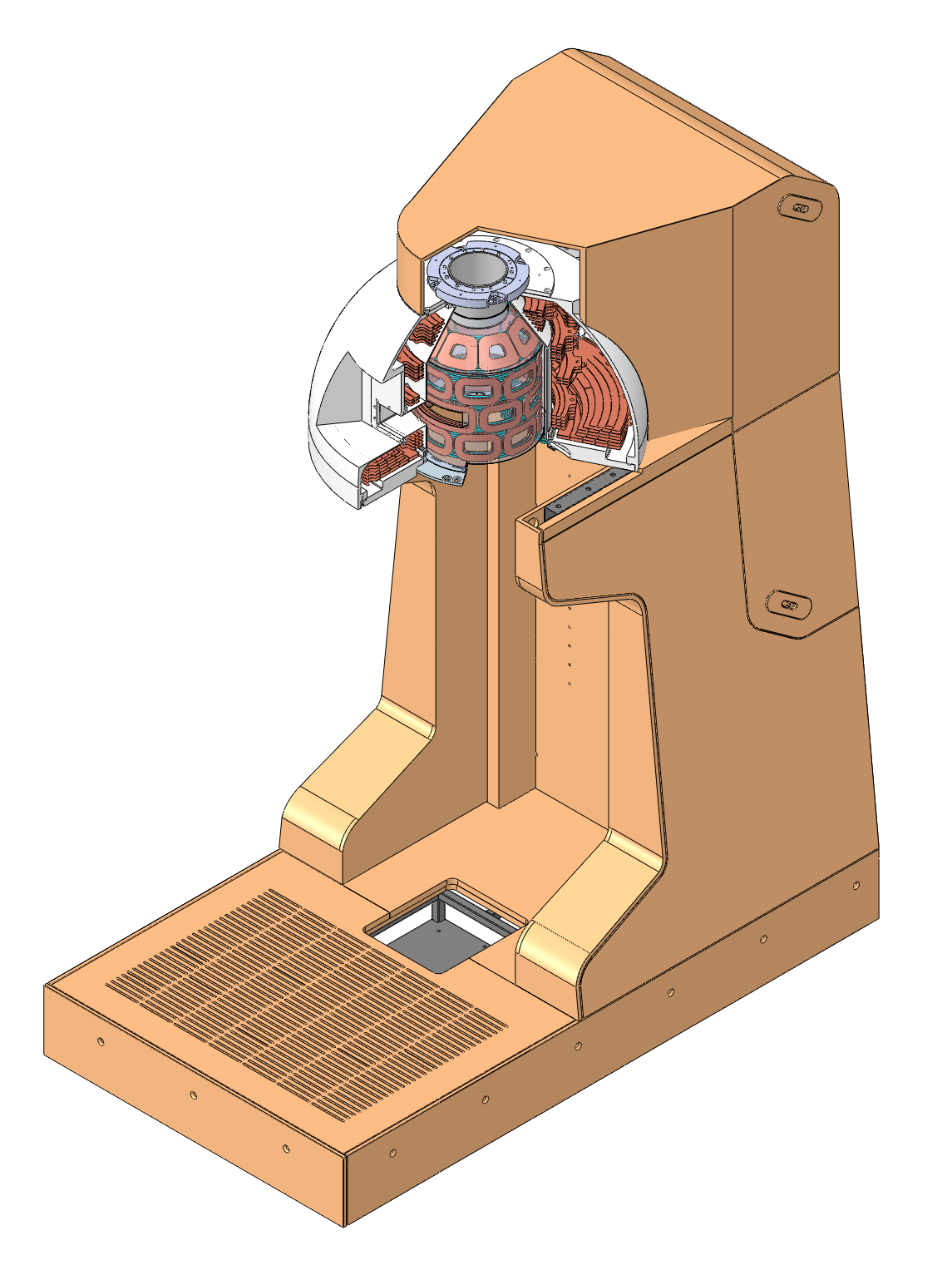
Recent attempts to improve accessibility to magnetic resonance imaging (MRI) relaxed various design principles, including historically high demands on the homogeneity of the magnet’s B0 field. The presence of strong B0 inhomogeneity, however, necessitates the usage of pulse sequences robust against off-resonance effects1-3 and potentially complex B0 shim fields. The dynamic multi-coil technique (DYNAMITE) is uniquely suited to provide both the (non-)linear image encoding fields necessary for such sequences, as well as highly localized B0 shim fields4,5 with the same set of coils.Here, we present construction and validation of multi-coil array (MCA) designed specifically for a compact 1.5 T head-only scanner6,7 whose magnet includes a patient window and excludes the subject’s shoulders to increase accessibility and enable novel motor-coordination studies. We describe the manufacturing of our prototype, its specifications, and experimentally validate its field generation capabilities as essential steps towards subsequent installation and use of this novel MCA in the 1.5 T head-only scanner.
Manufacturing
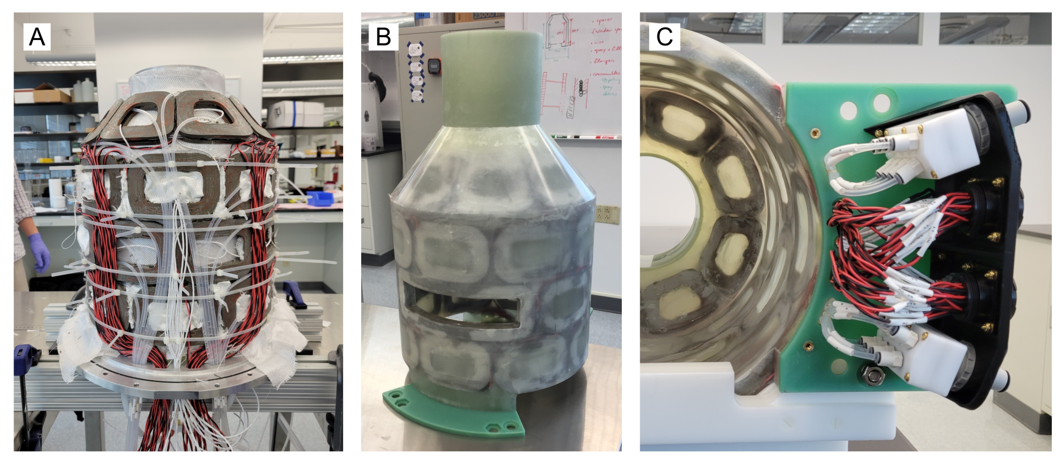
The MCA was designed as a compact system with an inner diameter of 300 mm, a radial thickness of 22 mm and an overall length of 530 mm. Four cylindrical rings of eight coils each are arranged on a cylindrical surface with the upper most ring tapered inwards to match the magnet’s geometry8. Two coils in the second ring are fused together to incorporate the patient window, resulting in 31 coils total. Each coil is a sandwich of an outer and an inner element of 100 turns of 20 AWG copper wire each, with PTFAN tubes for water-cooling running in the gap between both elements. Channels are driven individually with current up to 5 A.The coil elements were individually wet wound7,9 with epoxy and preassembled with cooling tubes into the four rings. Twisted pair lead wires were connected to all coils, 12 resistance temperature detectors (RTDs) were distributed throughout the coils, and everything was assembled inside a custom-made aluminum mold (Figure 2A). After adding woven glass fibers the setup was vacuum infused with epoxy resin.
Fiberglass flanges at the bottom and a tube at the top were added for mounting (Figure 2B), and all wires and cooling tubes were terminated at receptacles and custom-made manifolds, respectively, in a panel in the lower back of the system (Figure 2C).
Characterization
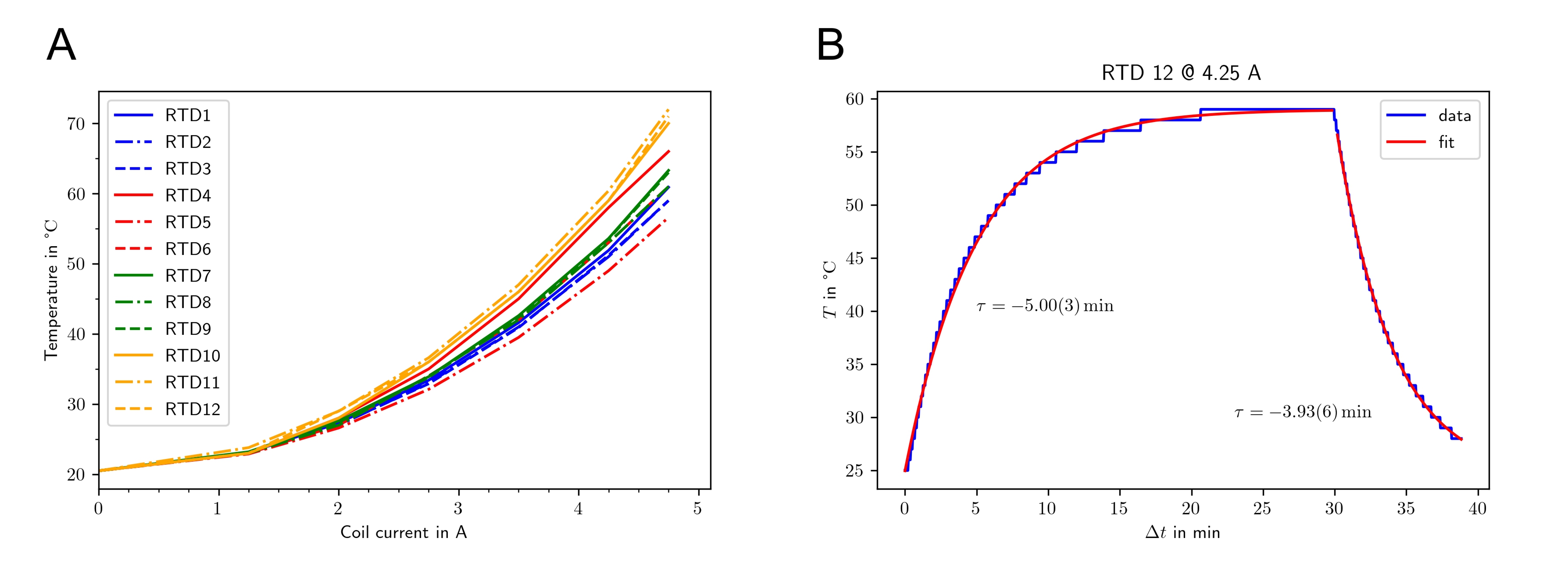
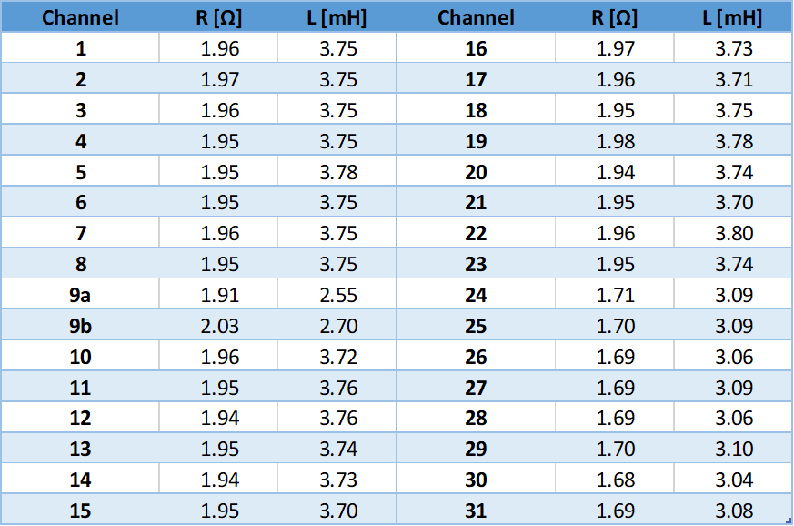
Resistances and inductances were measured individually for each channel (Table 1). The standard coils have a resistance of 1.95(1) Ω and an inductance of 3.75(2) mH, while the window coil elements and the conical coils have 1.97(6) Ω/2.62(8) mH and 1.69(1) Ω/3.08(2) mH, respectively. Connecting the system to a multi-channel amplifier system (Resonance Research Inc., Billerica, MA, USA) via a filter box added an additional 0.5 Ω and 0.2 mH to each channel. With the given specifications, and driving both window coil elements individually, the amplifier can ramp the MCA from 0 to 100% in 300 μs.Using a custom-made gradient controller10, the system was driven with constant currents applied to all coils while connected to a water chiller providing a total flow of 6 l/min at 20 °C through the cooling tubes. Steady-state coil temperatures increased with the applied current, with the window coil and the conical coils in the top ring showing the highest temperatures (Figure 3A). Reducing the water flow to 4 l/min did not significantly change the observed temperatures (not shown). The temperature curves closely fitted a mono-exponential function as expected with time constants in the order of 4 min (Figure 3B), which is long compared to the switching times in typical MRI sequences. For that reason, the presented steady-state experiment determines the system’s heating behavior at a given duty cycle. The maximum safe coil temperature was defined as 50 °C, corresponding to a maximum constant current of 3.5 A or a duty cycle of 70% at 5 A.
Field Generation
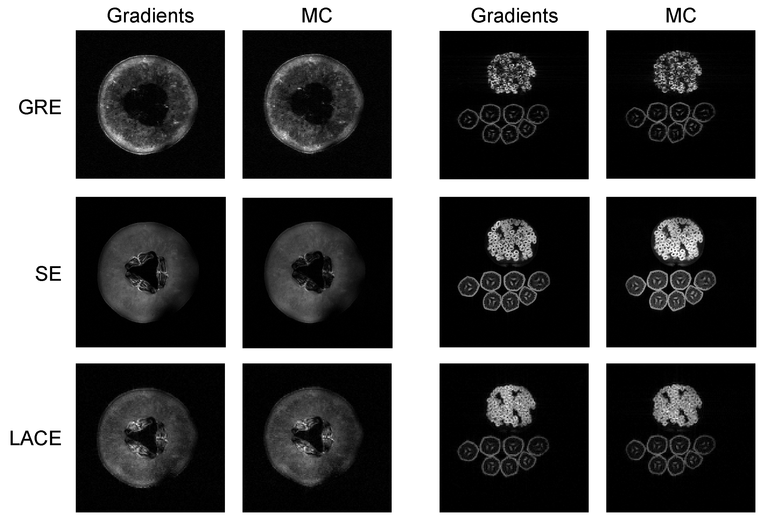
The MCA’s field generation capability was verified in a 4 T Bruker human scanner at the Yale MR Research Center. To this end, calibration maps (in Hz/A) of the MCA’s individual coils were measured by acquiring several B0 field maps at different current settings11. This calibration was then utilized to calculate optimal coil currents for various target fields using B0DETOX12,13.The MCA was tested on two different targets, a honeydew melon and a pomegranate on top of seven bananas. Three MRI sequences were used, multi-slice spin echo, 3D gradient echo and a recently presented low-angle-combined-echo sequence3 (Figure 4, image parameters in caption). All images were acquired using the scanner’s regular gradients system as well as using MC generated gradients only. Even though the imperfections of the generated fields are known, no image distortion correction was applied here.
Discussion & Outlook
We successfully designed and manufactured a prototype MCA for a novel accessible head-only MR scanner. The final system specifications closely match the design targets and predictions, with each channel being able to be driven with 5 A maximum by the designated multi-channel amplifier. The system’s high maximum duty cycle enables the generation of both image encoding and concomitant shim fields with the full dynamic range of the system.System integration with the overall accessible MR system is planned for early 2022.
Acknowledgements
This research was supported by the National Institutes of Biomedical Engineering & Bioengineering of the National Institutes of Health under award number U01EB025153.References
1. Patz S, Wong STS, Roos MS. Missing pulse steady‐state free precession. Magn Reson Med. 1989;10(2):194–209.
2. Kobayashi N, Parkinson B, Idiyatullin D, Adriany G, Theilenberg S, Juchem C, et al. Development and validation of 3D MP‐SSFP to enable MRI in inhomogeneous magnetic fields. Magn Reson Med. 2021;85(2):831–44.
3. Theilenberg S, Kumaragamage C, McIntyre S, Nixon TW, Juchem C, De Graaf RA. Low-Angle Combined-Echo (LACE) Imaging in Highly Inhomogeneous B0 Magnetic Fields. Proc Intl Soc Magn Reson Med. 2021;29:0004.
4. Juchem C, Nixon TW, Diduch P, Rothman DL, Starewicz P, de Graaf RA. Dynamic shimming of the human brain at 7 T. Concepts Magn Reson Part B Magn Reson Eng. 2010;37B(3):116–28.
5. Juchem C, Mullen M, Kumaragamage C, DelaBarre L, Adriany G, Brown PB, et al. Dynamic Multi-Coil Technique (DYNAMITE) MRI on Human Brain. Proc Intl Soc Magn Reson Med. 2019;27:0219.
6. Garwood M, Mullen M, Kobayashi N, DelaBarre L, Suddarth S, Idiyatullin D, et al. A compact vertical 1.5T human head scanner with shoulders outside the bore and window for studying motor coordination. Proc Intl Soc Magn Reson Med. 2020;28:1278.
7. Juchem C, Theilenberg S, Shang Y, Ghazouani J. Magnetic Resonance Imager with Coils for Arbitrary Image Space and Fabrication Thereof. US Patent WO2021/022252, February 4, 2021.
8. Theilenberg S, Shang Y, Kobayashi N, Parkinson BJ, Juchem C. Multi-Coil Array for Combined Imaging and B0 Shimming in a Portable Head-Only Scanner. Proc Intl Soc Magn Reson Med. 2019;27:1480.
9. Shang Y, Theilenberg S, Ghazouani J, Juchem C. A Coil-Winding Machine for Wet-Winding of Resin-Impregnated Curved Wire Patterns. Proc Intl Soc Magn Reson Med. 2020;28:4248.
10. Nixon TW, McIntyre S, de Graaf RA. The Design and Implementation of a 64 Channel Arbitrary Gradient Waveform Controller. 2017;25:0969.
11. de Graaf RA, Juchem C. CHAPTER 4. B0 Shimming Technology. In: Webb A, editor. Magnetic Resonance Technology: Hardware and System Component Design. Cambridge, UK: The Royal Society of Chemistry; 2016:166–207.
12. Juchem C. B0DETOX - B0 Detoxification Software for Magnetic Field Shimming. Columbia University Technology Ventures; 2017. Available from: http://innovation.columbia.edu/technologies/cu17326_b0detox
13. Juchem C, Herman P, Sanganahalli BG, Brown PB, Mcintyre S, Nixon TW, et al. DYNAmic Multi-coIl TEchnique (DYNAMITE) shimming of the rat brain at 11.7T. NMR Biomed. 2014;27(8):897–906.
Figures