0641
MR System Stability and Quality Control using Gradient Impulse Response Functions (GIRF)1Techna Institute, University Health Network, Toronto, ON, Canada, 2UBC MRI Research Center, University of British Columbia, Vancouver, BC, Canada, 3Department of Physics, Norwegian University of Science and Technology, Trondheim, Norway, 4Techna Institute & Koerner Scientist in MR Imaging, University Health Network, Toronto, ON, Canada, 5Biomedical Engineering, Center for Neuroscience Imaging Research, Institute for Basic Science, Sungkyunkwan University, Suwon, Korea, Republic of
Synopsis
This study investigated the long-term stability of GIRF within an eight-month period, together with the benefits of an optimized GIRF acquisition protocol. These studies provide insight into mechanisms of image quality degrading and potentially lead to improved image quality control, generalizable to arbitrary imaging sequences.
Introduction
System imperfections alter the actual gradient waveform from the ideal one, which is a common source of image quality degrading in many MRI sequences, especially for non-Cartesian imaging. Although the actual gradient waveform is measurable [1], a generalized approach to characterize this system imperfection is using the gradient impulse response function (GIRF) [2, 3], which considers the gradient as a linear time-invariant system to an input waveform. This method has been successfully implemented on non-Cartesian methods such as spiral [4] and wave-encoded [5] images. Quality control for these gradient system errors is a major concern in longitudinal and multi-site MRI studies, and GIRF characterization provides a general approach with mechanistic insights to the quality degradation and corrections. In this study, we investigate the long-term stability of the GIRF and propose an optimized GIRF measurement protocol and quality metrics to enable GIRF-based gradient system quality control.Methods
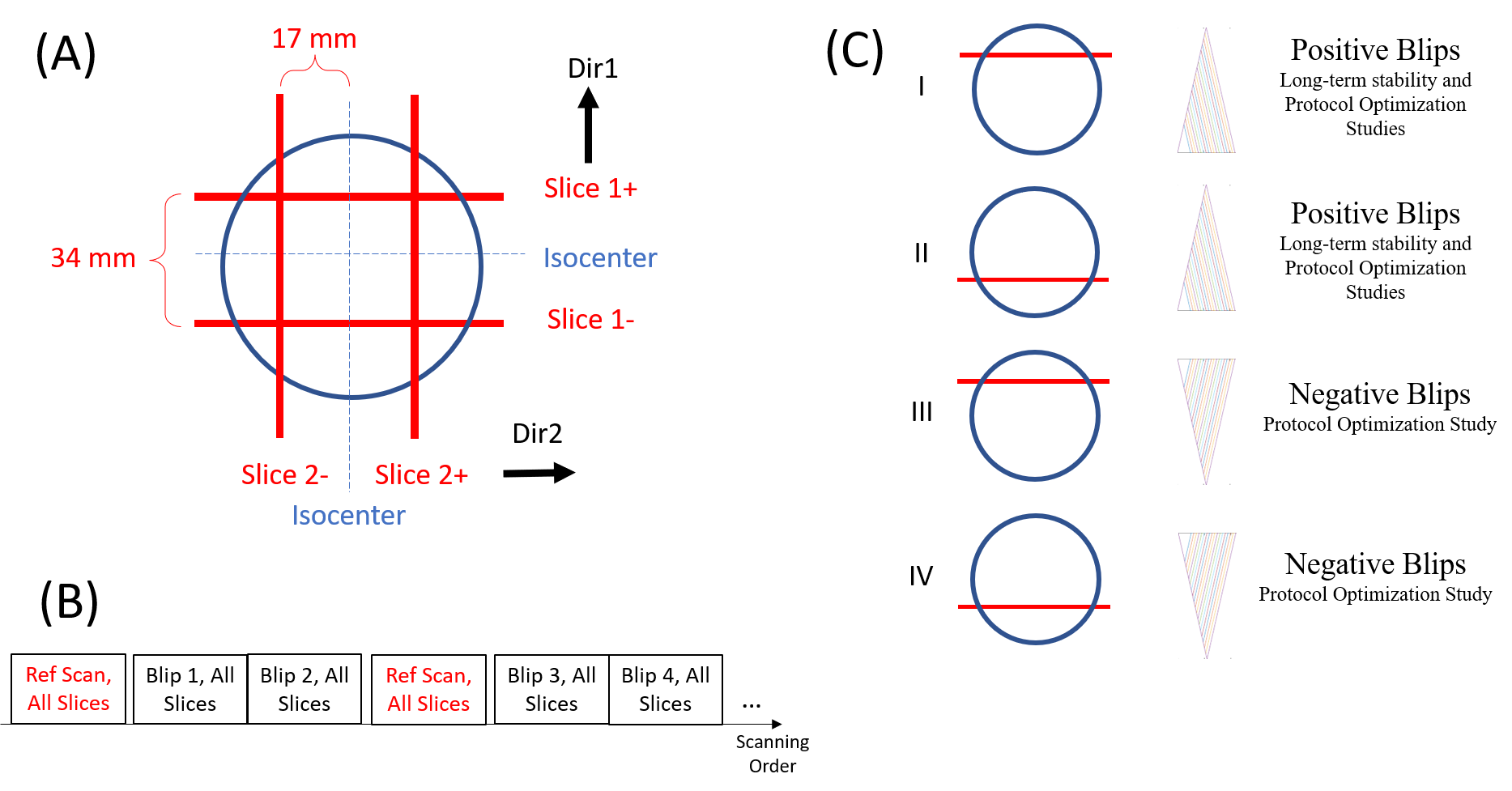
A sphere phantom was used on a 3T Siemens Prisma scanner with a modified thin-slice GRE sequence with gradient blips after excitation to acquiring T2* decays [3]. The common parameters were: ADC duration 50 ms with a dwell time of 5 us; gradient blip started 2 ms after excitation with 180 T/m/s slew rate, and a total of 18 blips applied with amplitudes from 9 to 39.6 mT/m [1]; 50 repetitions for each blip amplitude. Two symmetric slices with 1mm thickness and 17 mm distance from isocenter were excited on each gradient direction (Figure 1A). A reference scan with blip-off and 5 repetitions was inserted between each two consecutive blip amplitudes to cancel gradient drifting over time (Figure 1B).GIRF is calculated through multiple pairs of input-output signal as
$$\hat{H}(\omega)=\frac{{\Sigma_{j} I^{*}_{j} (\omega) \hat{O}_{j}(\omega) }} {{\Sigma_{j}|I_{j}(\omega)|^2}}$$
in which $$$I$$$ is the input gradient blips, is the phase evolution from the output signal we acquired, $$$j$$$ is the index of input/output pairs (from 1 to 18 in this study).
Two studies were performed in this work (Figure 1C).
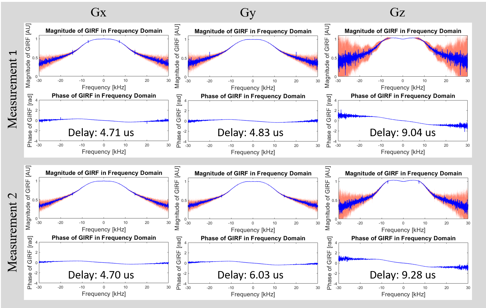
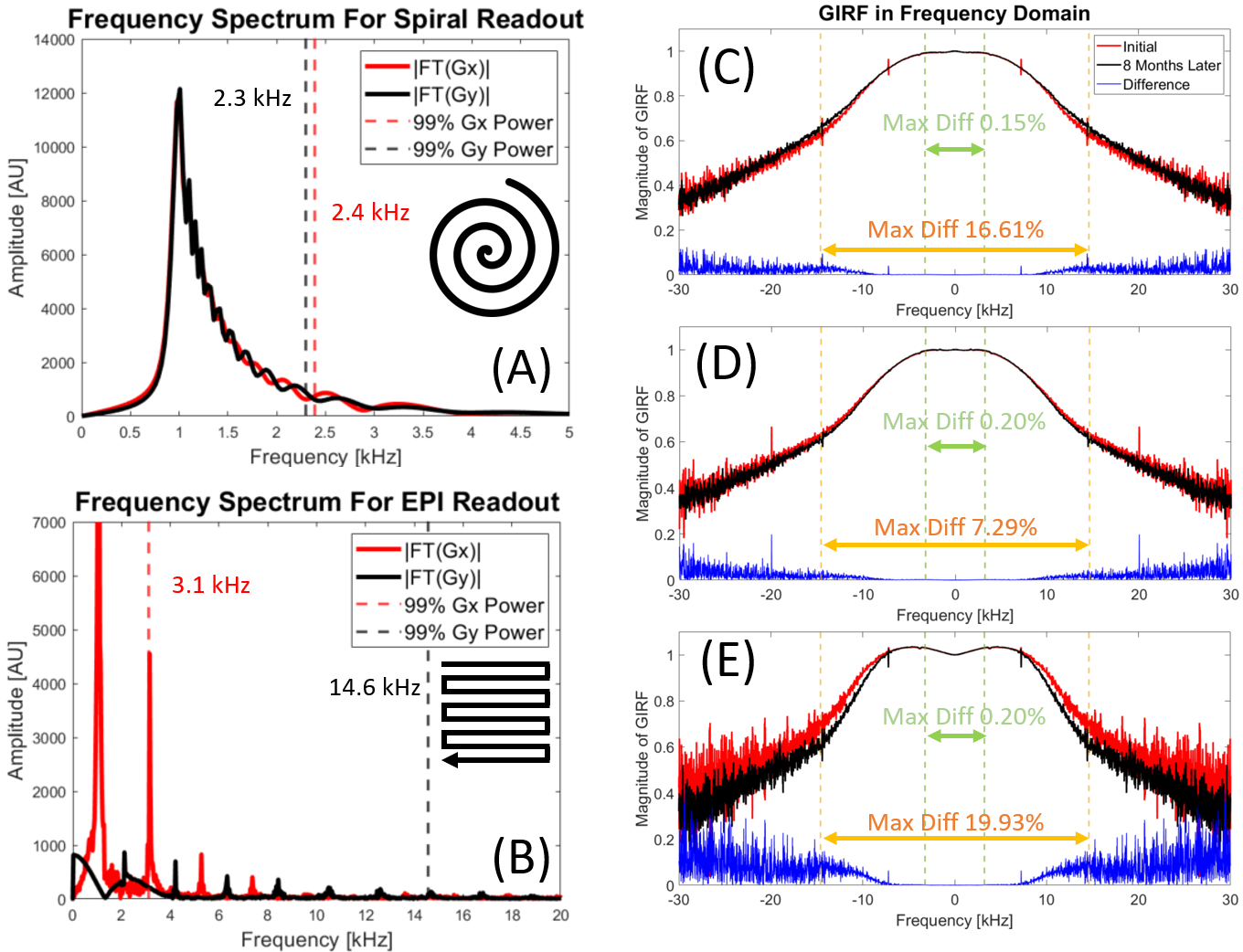
(1) Long-term stability: Two datasets with only positive blip polarity were acquired with abovementioned sequence and parameters in an eight-month period. The gradient delays were calculated by fitting the phase ramp of GIRF in frequency domain. GIRF amplitude differences in two frequency ranges (±3.2kHz and ±14.6kHz) were calculated, which typically contain > 99% of power for spiral and EPI readout gradients, respectively (Figure 3A and 3B). The large cut-off frequency on Gy for EPI readout is due to much wider distribution of Gy blips (Figure 3B black spectrum line).
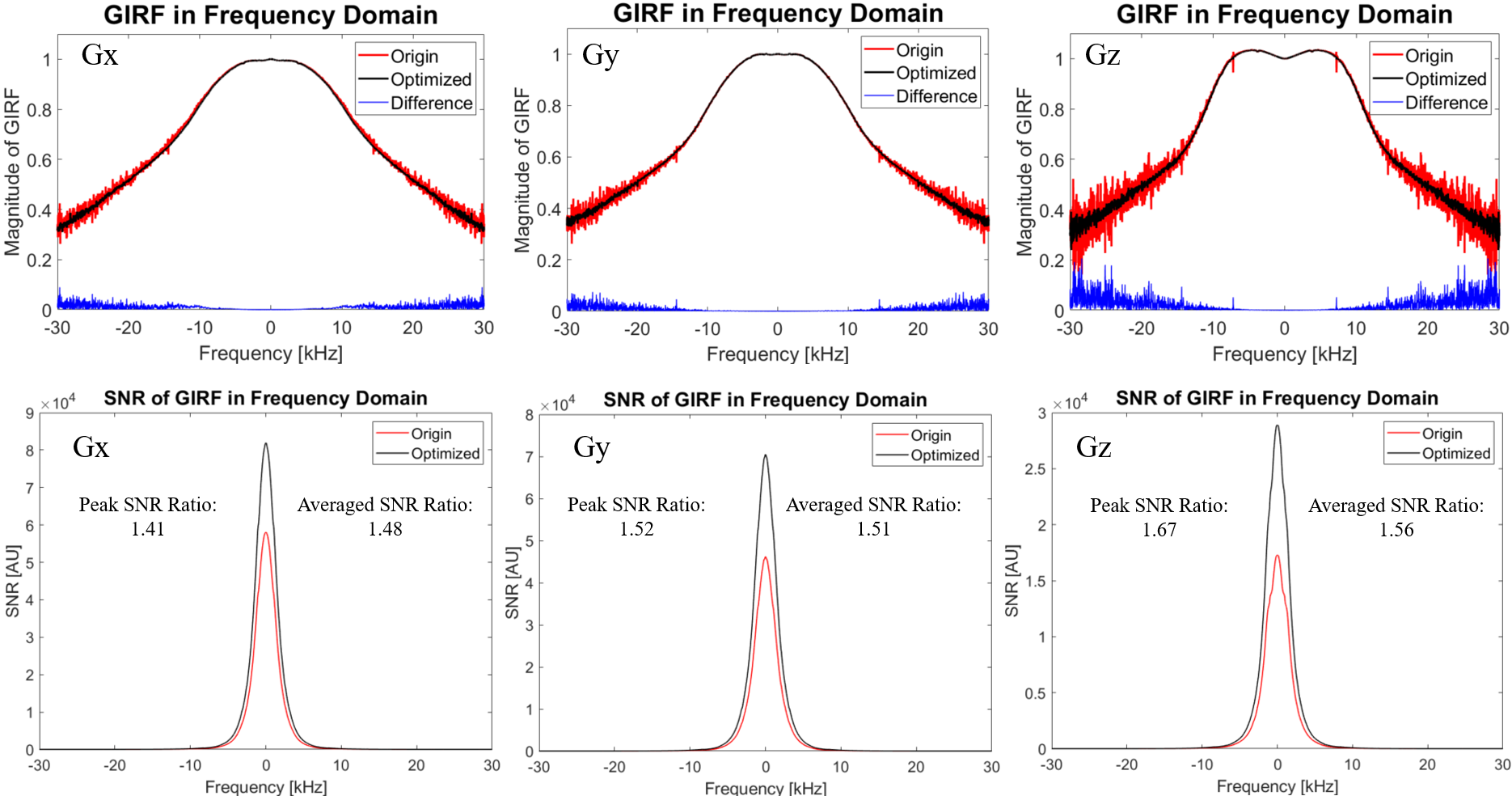
(2) GIRF protocol optimization: Two additional datasets were acquired in the most recent experiment, using negative polarity of gradient blips while keeping other parameters the same. GIRFs and their signal-to-noise ratios were calculated using both positive/negative blips [6] and were subsequently compared to the ones calculated only using positive blips.
Results
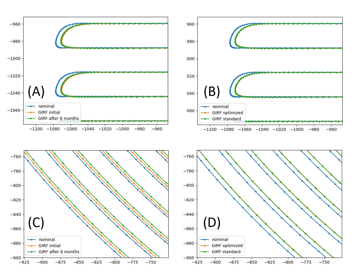
Figure 2 illustrates two sets of GIRFs in an eight-month period for the long-term stability study, with mean and standard deviation of all 50 repetitions. The results show both GIRFs with a similar curve shape, noise level, and temporal delays. Figure 3 further demonstrates the maximum signal differences under the ranges of ±3.2kHz and ±14.6kHz, which reflect frequencies of interest for typical EPI and spiral trajectories. This change is negligible (≤ 0.2%) within ±3.2kHz, indicating robust long-term stability; however, for ±14.6kHz range, this change could be up to 20%. Figure 4 shows the GIRF before and after protocol optimization, together with the SNR improvements. Both peak and averaged SNR improvements are close to the theoretical prediction of improvement as after protocol optimization there is one more average to the output signal during GIRF calculation. Figure 5 demonstrates the correction results of the typical spiral and EPI after being corrected with two sets of GIRFs in both long-term stability and protocol optimization studies.Discussion and Conclusion
The comparison between two measurements in the long-term study reveals relatively high stability within the range of ±3.2kHz, which covers most of the popular readout gradients including spiral and Gx EPI readouts. The range of ±14.6kHz reveals a larger GIRF fluctuation, indicating a potentially higher impact to blip gradients in EPI readout, especially when using Gz.Furthermore, the SNR of the GIRF measurements is reduced in the high-frequency range, because (1) the gradient system is a low-pass filter, and (2) both the input and output signal has limited energy in the high-frequency range. While the optimized protocol significantly improved GIRF SNR, the differences for typical trajectories were negligible, pointing to the robustness of the GIRF measurement itself for QC purposes.
We also observed a significantly higher noise level and lower long-term stability in the Gz GIRF than the other two axis, presumably due to the different physical construction of the Gz (Helmholtz) vs Gx,Gy (saddle) gradient coils, which might have implications for slice orientation choices in long-term studies.
In conclusion, this study investigated the long-term stability of GIRF within an eight-month period, together with the benefits of an optimized GIRF acquisition protocol. These studies provide insight into mechanisms of image quality degrading and potentially lead to improved image quality control, generalizable to arbitrary imaging sequences.
Acknowledgements
The authors appreciate the support from Dr. Morgan Barense, Dr. Ali Golestani and Ms. Priya Abraham from Toronto Neuroimaging Facility (ToNI), Department of Psychology, University of Toronto.References
[1] Duyn, J. H., Yang, Y., Frank, J. a, & van der Veen, J. W. (1998). Simple Correction Method fork-Space Trajectory Deviations in MRI. Journal of Magnetic Resonance, 132(1), 150–153. https://doi.org/10.1006/jmre.1998.1396
[2] Vannesjo, S. J., Haeberlin, M., Kasper, L., Pavan, M., Wilm, B. J., Barmet, C., & Pruessmann, K. P. (2013). Gradient system characterization by impulse response measurements with a dynamic field camera. Magnetic Resonance in Medicine, 69(2), 583–593. https://doi.org/10.1002/mrm.24263
[3] Graedel, N. N., Hurley, S. A., Clare, S., Miller, K., Pruessmann, K. P., & Vannesjo, S. J. (2017). Comparison of gradient impulse response functions measured with a dynamic field camera and a phantom-based technique. ESMRMB 2017, 34th Annual Scientific Meeting, Barcelona, ES, October 19–October 21: Abstracts, Saturday, 30(S1), 343–499. https://doi.org/10.1007/s10334-017-0634-z
[4] Vannesjo, S. J., Graedel, N. N., Kasper, L., Gross, S., Busch, J., Haeberlin, M., Barmet, C., & Pruessmann, K. P. (2016). Image reconstruction using a gradient impulse response model for trajectory prediction. Magnetic Resonance in Medicine, 76(1), 45–58. https://doi.org/10.1002/mrm.25841
[5] Stich, M., Wech, T., Slawig, A., Ringler, R., Dewdney, A., Greiser, A., Ruyters, G., Bley, T. A., & Köstler, H. (2018). Gradient waveform pre-emphasis based on the gradient system transfer function. Magnetic Resonance in Medicine, 80(4), 1521–1532. https://doi.org/10.1002/mrm.27147
[6] Robison, R. K., Li, Z., Wang, D., Ooi, M. B., & Pipe, J. G. (2019). Correction of B0 eddy current effects in spiral MRI. Magnetic Resonance in Medicine, 81(4), 2501–2513. https://doi.org/10.1002/mrm.27583
Figures