0636
The MotoNet: An MRI-Compatible EEG Net with Embedded Motion Sensors1Athinoula A. Martinos Center for Biomedical Imaging, Massachusetts General Hospital, Charlestown, MA, United States, 2Department of Biomedical Engineering, Boston University, Boston, MA, United States
Synopsis
We introduce a new EEG net, which will allow clinicians to monitor EEG while tracking head motion for correction. Motion during MRI limits patient scans, especially of children and patients with seizures. The MotoNet was built using PTF, embedding EEG/motion sensor pairs on opposite sides in one circuit. MRI safety studies at 3T confirmed maximum heating below 1ºC. EEG/motion measurements were made with a standard commercial EEG system. Using a custom MRI sequence with spatial localization gradients only, we showed that the signal on each channel was highly correlated with motion, allowing for electrode positioning and motion tracking.
INTRODUCTION
Head motion during clinical neuroimaging results in compromised image quality and diagnosis, especially in the sickest patients, and results in substantial lost revenue for imaging centers (1). In research scans, blurring and other artifacts can bias scientific conclusions. Navigators and camera-based systems are commonly used to track and correct motion in real-time but require sequence changes or a clear line-of-sight to the patient in the head coil. Small pick-up coils rigidly attached to the patient's head have been previously used for motion tracking (2), and others have shown that motion tracking is feasible during simultaneous EEG-fMRI using standard MRI conditional EEG amplifiers (3,4). Here we introduce a new EEG net, the "MotoNet" that has 32 loops/sensors embedded alongside 32 EEG electrodes. Since the voltage induced flux in each sensor is dependent on the position and orientation of the sensor in the gradient field (5,6), the combination of rigidly-related sensors allows tracking of the head motion. This measurement is more precise than EEG, which is less focal as it records gradient artifact signals from the entire volume conductor of the head.METHODS
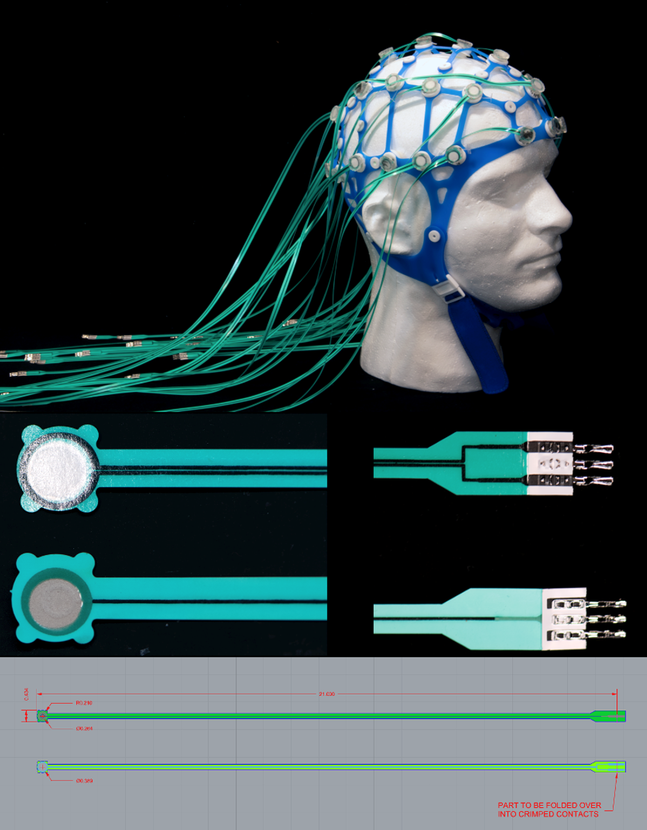
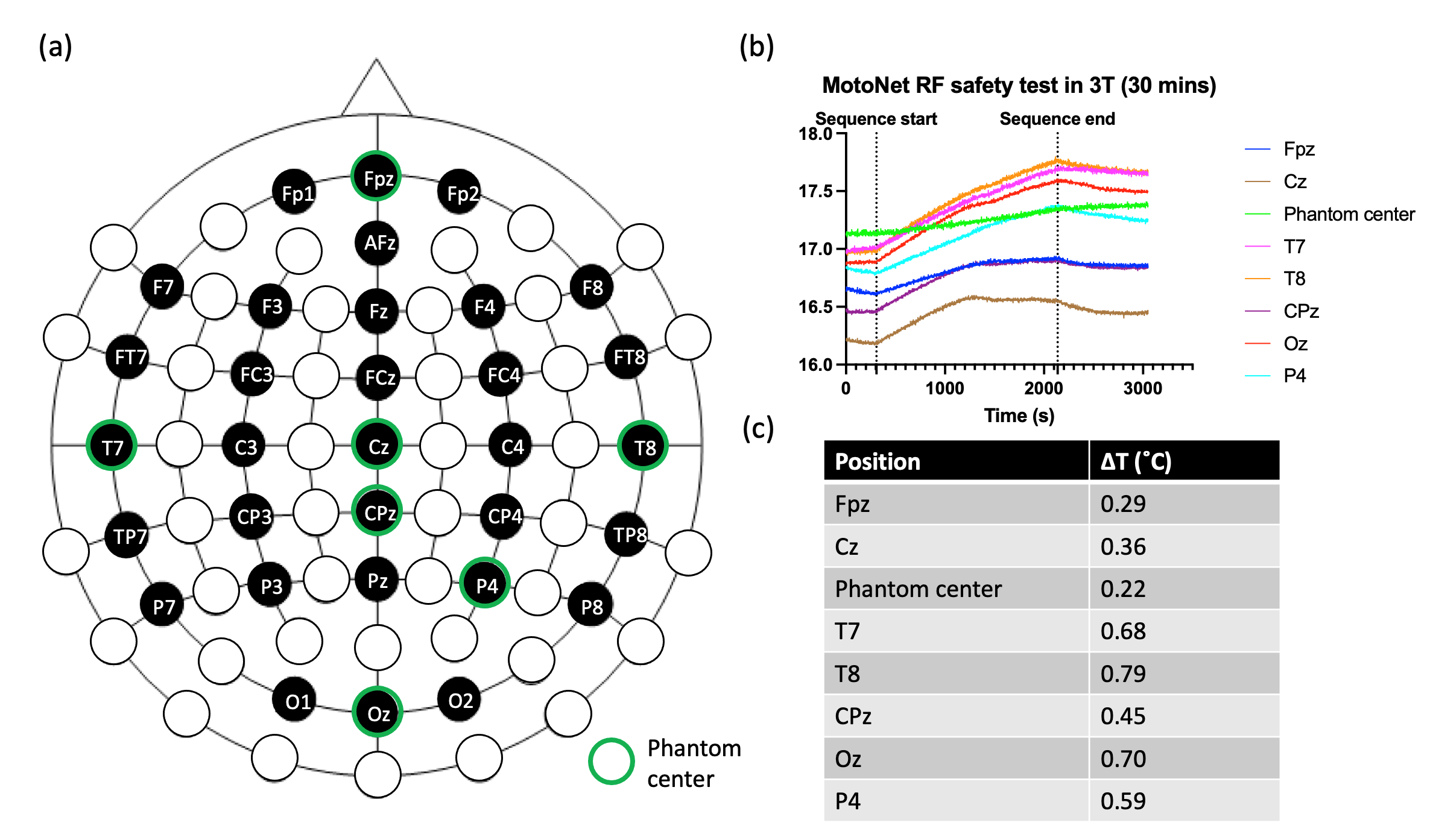
Fabrication: High-resistance Polymer Thick Film (PTF) technology (Fig. 1) was adopted to fabricate electrode pads and leads ($$$\overline{R_{trace}}$$$=17.47±0.95 kΩ). Conductive inks (Engineered Conductive Materials, OH, USA) were screen-printed onto Melinex (DuPont Teijin Films U.S. Limited Partnership, VA, USA) substrate with EEG electrodes on one side and a loop on the opposite side ($$$\overline{R_{trace}}$$$=41.61±2.07 kΩ). The MotoNet circuits fit in a commercial elastomer structure, and the PTF leads were passed through the wire-tunnel of a Siemens Head/Neck 64 coil and connected to a 64-channel Brain Products amplifier system through a custom-made interface.Safety: The RF safety of the MotoNet was tested in a 3T MRI (Prisma, Siemens Healthineers) using a head-sized agar phantom (Fig. 2). A high-power turbo spin-echo sequence was set to produce 3.2 W/kg in the head for 30 minutes. The dielectric properties of the phantom were selected to be similar to the adult brain properties at 3T (7,8). The 8-channel optic probes were positioned at distributed locations across MotoNet, including three hot-spots estimated from thermal simulation (9).
Sensor Pose Estimation Theory
The voltage vi induced flux in a loop i depends on the orientation of the loop with respect to the changing magnetic flux:
$$v_i\left(t\right)=a_{xi}\left(t\right)\frac{\partial B_x\left(t\right)}{\partial t}+a_{yi}\left(t\right)\frac{\partial B_y\left(t\right)}{\partial t}+a_{zi}\left(t\right)\frac{\partial B_z\left(t\right)}{\partial t}$$
where the orientation is encoded in the areas axi, ayi and azi of the sensor loop projected on the planes perpendicular to the normal in the x, y, and z directions, respectively. The location of the coil is encoded by the gradients which are designed to generate a field with a z-component that varies linearly with the distance from the gradient isocenter. However, Maxwell's equations predict unavoidable orthogonal field components (5):
$$\left(\begin{matrix}B_x\left(t\right)\\B_y\left(t\right)\\B_z\left(t\right)\\\end{matrix}\right)=\left(\begin{matrix}-{\frac{1}{2}}G_z\left(t\right)&0&G_x\left(t\right)\\0&-{\frac{1}{2}}G_z\left(t\right)&G_y\left(t\right)\\G_x\left(t\right)&G_y\left(t\right)&G_z\left(t\right)\\\end{matrix}\right)\left(\begin{matrix}x\\y\\z\\\end{matrix}\right)$$
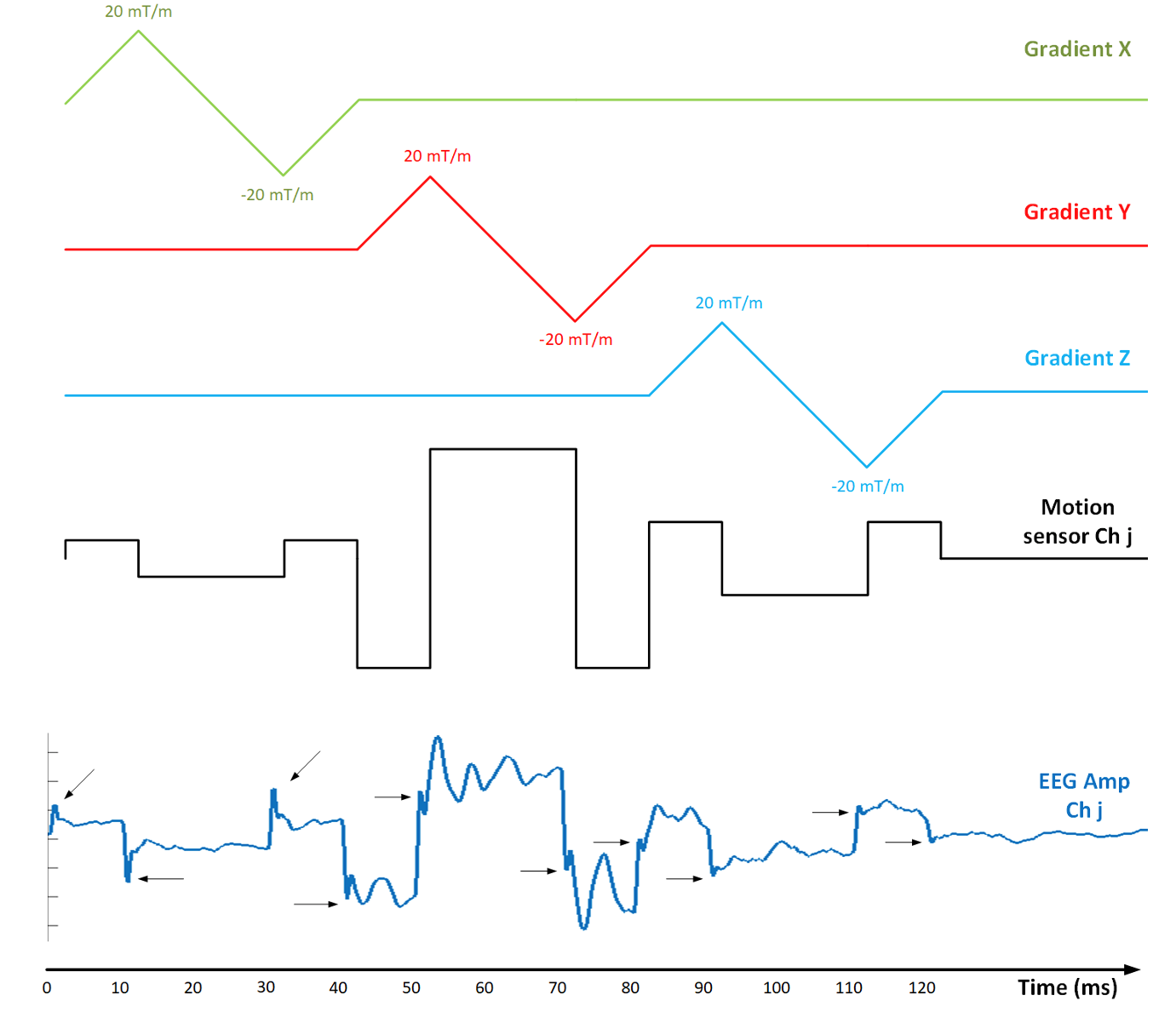
Since the sensor detects the time-varying component of the field, the magnet's main field is irrelevant. Furthermore, we design the time-varying gradient waveforms to vary with a constant ramp of m (mT/m/ms) as shown in Fig. 3 (10). We average the response across the three slopes of the triangular waveform, accounting for the sign. This waveform is repeated independently on the x, y, and z axes with the same amplitude. We, therefore, expect the induced voltages vxi, vyi and vzi to depend on position and orientation at an instant as follows:
$${R}_i={A}_i\bullet\ T_i$$
$$\begin{matrix}{R}_i=\left(\begin{matrix}x_{1,i}&\cdots&z_{1,i}\\\vdots&\ddots&\vdots\\x_{4,i}&\cdots&z_{4,i}\\\end{matrix}\right),&{T}_i=\left(\begin{matrix}v_{1,i}^x&\cdots&v_{4,i}^x\\\vdots&\ddots&\vdots\\v_{1,i}^z&\cdots&v_{4,i}^z\\\end{matrix}\right)\\\end{matrix}$$
The geometry of the ensemble of 32 sensors is known from the SPOT3D (11) (ANT128). The eight local affine transformation matrices $$${A}_{i}$$$ represents the local transformation matrices between the sensor space location and the voltage space. Each $$${A}_{i}$$$ was estimated using 4 neighboring points in sensor space (Ri) and 4 points in voltage space (Ti) using a linear equation:
$$A_i=R_i\bullet\ {T_i}^{-\mathbf{1}}$$
Phantom Motion Tracking Scans
We placed the head-shaped agar phantom in a 3T Siemens Prisma scanner and imaged it with a 2 mm isotropic MPRAGE in the initial plus three other positions. The x-,y-,z- gradient responses were measured and estimated using motion sensors that are ensemble-averaged across epochs (128 repetitions). We used "robust register" (12) to obtain the pose in each position relative to the initial position. The TCL markerless tracker (TracInnovations, Denmark) was used to estimate the pose of the phantom.
RESULTS
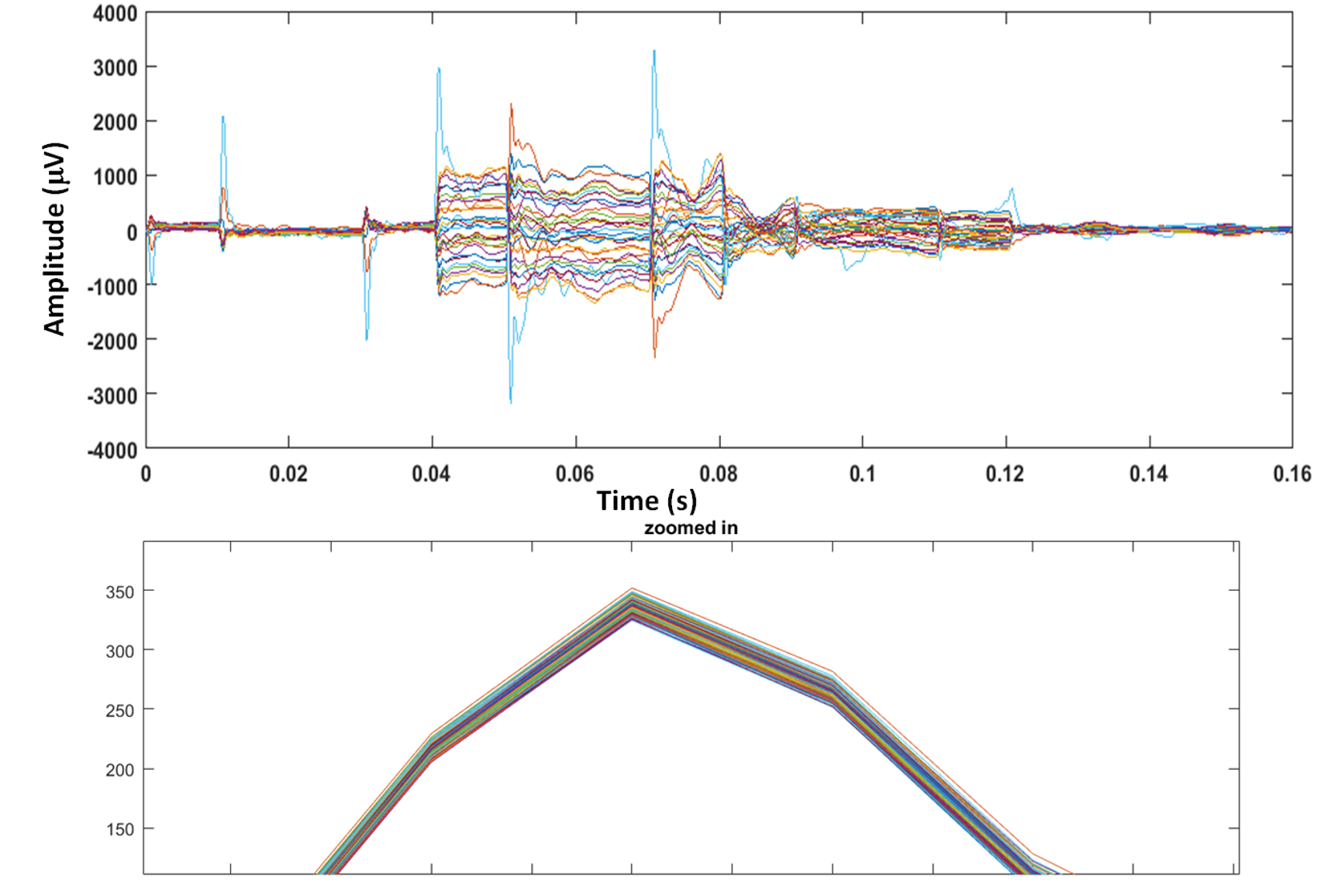
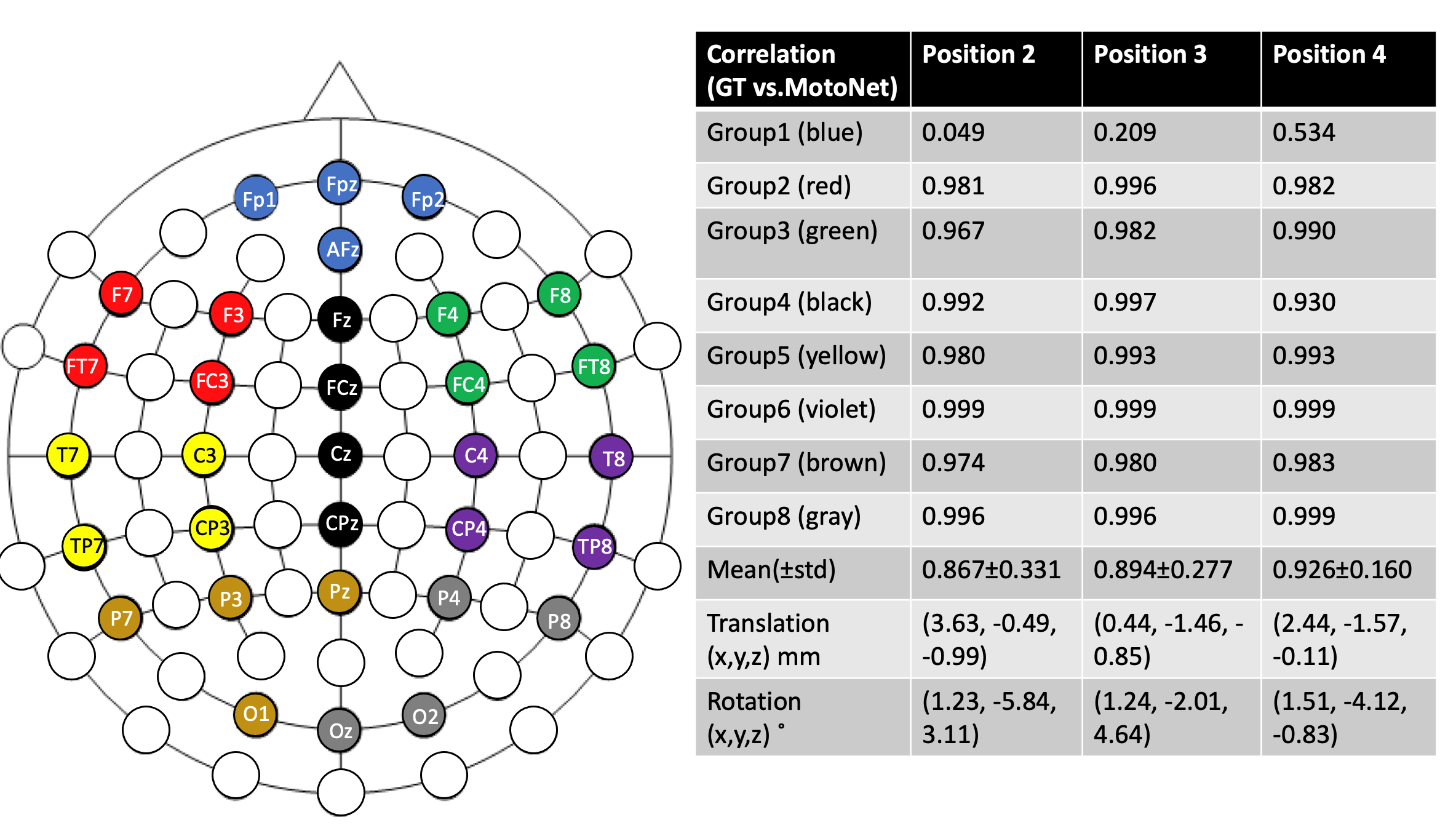
Safety: The maximum temperature rise was found to be 0.79 ˚C (Fig. 2), which is an acceptable temperature increase according to FDA guidance (13).Phantom Scans: Fig. 4 shows the voltage signals recorded in the motion sensors. The strong impulse response observed at the time of gradient change was excluded from the data analysis. Fig. 5 shows the correlation between the transformation estimated from the TCL tracker and the neighboring subsets of motion sensors at three different positions of the phantom. Overall, correlation was estimated as 0.896 ± 0.03, demonstrating a strong relationship between the motions and voltage responses shown in the motion sensors.
CONCLUSION
We demonstrated that the MotoNet is MRI safe and the signals from the motion sensors correlate with the pose of the head. In future work we will estimate head position by modeling the sensor positions and orientations based on the known geometry of the MotoNet and the anatomical image of the patient's head.Acknowledgements
This work was funded by NIH/NIBIB grant R01EB024343 and NIH S10OD025253.References
1. Andre JB, Bresnahan BW, Mossa-Basha M, Hoff MN, Smith CP, Anzai Y, Cohen WA. Toward Quantifying the Prevalence, Severity, and Cost Associated With Patient Motion During Clinical MR Examinations. J Am Coll Radiol 2015;12:689–695.
2. van Niekerk A, van der Kouwe A, Meintjes E. Toward “plug and play” prospective motion correction for MRI by combining observations of the time varying gradient and static vector fields. Magn Reson Med 2019;82:1214–1228.
3. Wong C-K, Zotev V, Misaki M, Phillips R, Luo Q, Bodurka J. Automatic EEG-assisted retrospective motion correction for fMRI (aE-REMCOR). NeuroImage (Orlando, Fla) 2016;129:133–147.
4. Laustsen M, Andersen M, Lehmann PM, and Rong Xue, and Kristoffer H. Madsen, and Lars G. Hanson. Slice-wise motion tracking during simultaneous EEG-fMRI. In: Proceedings 26. Annual Meeting International Society for Magnetic Resonance in Medicine. Vol. 26. Paris, France: \url{http://archive.ismrm.org/2018/4082.html}; 2018. p. 4082.
5. Bernstein MA, Zhou XJ, Polzin JA, King KF, Ganin A, Pelc NJ, Glover GH. Concomitant gradient terms in phase contrast MR: Analysis and correction. Magn Reson Med 1998;39:300–308.
6. Laustsen M, Andersen M, Madsen KH, Hanson LG. Gradient distortions in EEG provide motion tracking during simultaneous EEG-fMRI. ISMRM Work Motion Correct MRI & MRS 2017.
7. Hasgall P, Di Gennaro F, Baumgartner C, Neufeld E, Lloyd B, Gosselin M, Payne D, Klingenböck A, Kuster N. IT’IS Database for thermal and electromagnetic parameters of biological tissues. IT’IS Found 2018:Version 4.0.
8. Duan Q, Duyn JH, Gudino N, De Zwart JA, Van Gelderen P, Sodickson DK, Brown R. Characterization of a dielectric phantom for high-field magnetic resonance imaging applications. Med Phys 2014;41:10–305.
9. Atefi SR, Serano P, Poulsen C, Angelone LM, Bonmassar G. Numerical and Experimental Analysis of Radiofrequency-Induced Heating Versus Lead Conductivity During EEG-MRI at 3 T. IEEE Trans Electromagn Compat 2019;61:852–859.
10. Gholipour A, Polak M, Kouwe A van der, Nevo E, Warfield SK. Motion-robust MRI through real-time motion tracking and retrospective super-resolution volume reconstruction. In: 2011 Annual International Conference of the IEEE Engineering in Medicine and Biology Society. ; 2011. pp. 5722–5725.
11. Taberna GA, Guarnieri R, Mantini D. SPOT3D: Spatial positioning toolbox for head markers using 3D scans. Sci Rep 2019;9:12813.
12. Reuter M, Rosas HD, Fischl B. Highly accurate inverse consistent registration: A robust approach. Neuroimage 2010;53:1181–1196.
13. U.S. Food and Drug Administration. Testing and Labeling Medical Devices for Safety in the Magnetic Resonance (MR) Environment: Guidance for Industry and Food and Drug Administration Staff. US Food Drug Adm Doc / FIND 2021.
Figures