0580
Increasing Peripheral Nerve Stimulation Thresholds Using Gradient Array Coils1Department of Electrical and Electronics Engineering, Bilkent University, Ankara, Turkey, 2National Magnetic Resonance Research Center (UMRAM), Bilkent University, Ankara, Turkey
Synopsis
Recent high-performance gradient coil designs are primarily limited by Peripheral Nerve Stimulation thresholds rather than hardware. Electrical fields induced by gradient switching may stimulate nerves within the human body if they exceed predefined thresholds. Gradient array coils can reduce the maximum electric field by optimizing feeding currents while generating the desired magnetic field profile within a specified region of interest. Another degree of freedom provided by array configuration is the ability to generate a flexible shaped region of interest, which allows for electrical fields manipulation to increase peripheral nerve stimulation thresholds.
Introduction
The use of high-performance gradient coils in MRI has become significantly limited due to Peripheral Nerve Stimulation (PNS). The rapid switching of strong gradients induces electric fields (E-fields) within the human body results in stimulating nerves. Head-insert gradient coils with smaller linear Region of Interest (ROI) were developed to increase PNS thresholds1-3. Despite these efforts, recent gradient design algorithms incorporate constraints on the E-fields leading to PNS-optimized gradient coils4,5; However, further optimization cannot be performed after coil fabrication. On the other hand, gradient array coil consists of multiple coils6-9, which can be independently driven by separate power amplifiers, are capable of generating tunable field profiles (B- and E-field) within a flexible ROI by optimizing the feeding waveforms. This work shows that E-field produced by a gradient coil can be significantly reduced when linearity is needed in a small ROI, demonstrating the power of a gradient array coil.Methods
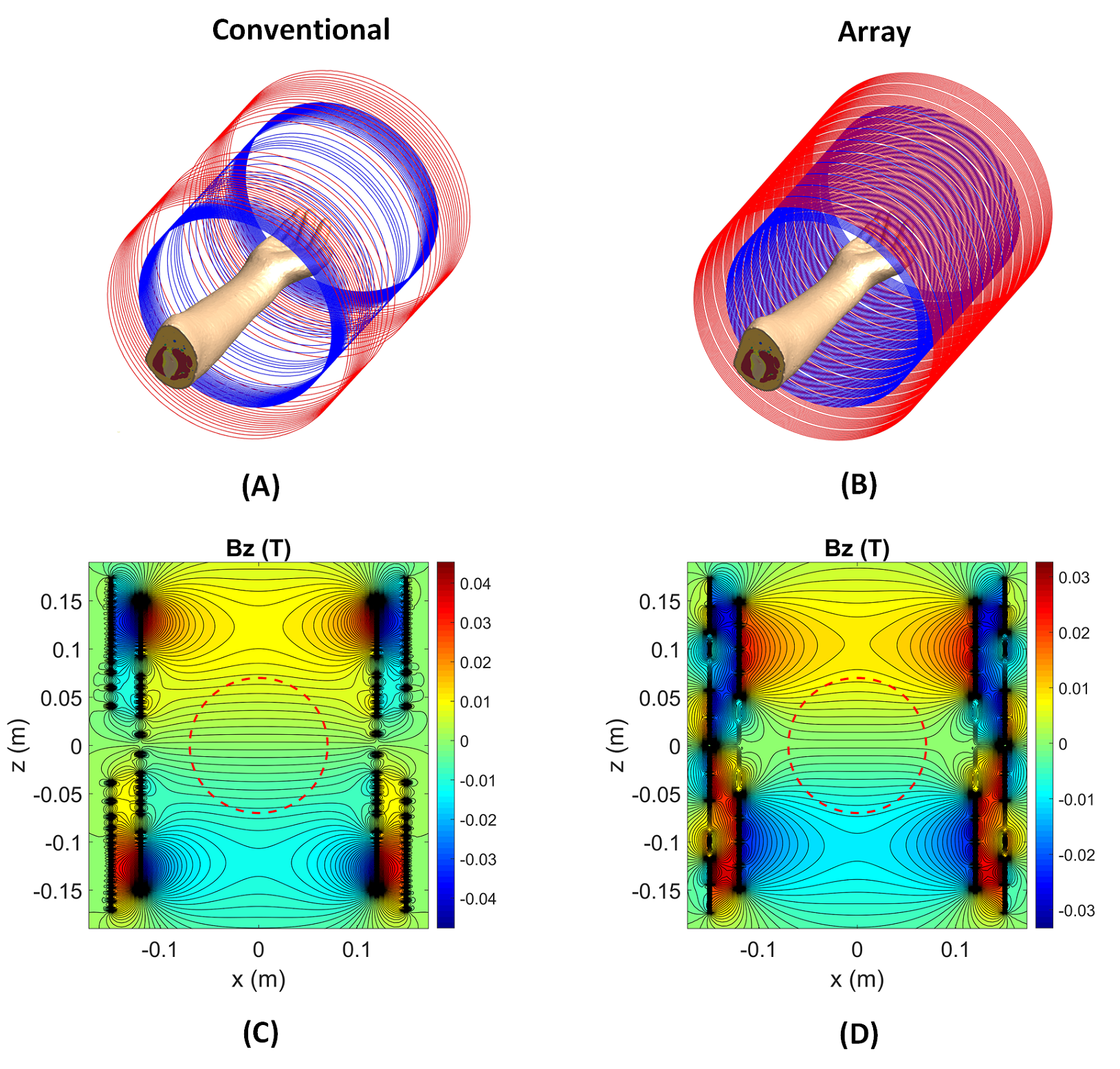
A z-gradient array coil was used to demonstrate the substantial reduction of the electric field. The coil comprises primary and shield coils, each with 12 pairs of wire bundles (10 wires per bundle) and diameters/heights of 24/30 and 30/35 cm, respectively. This coil generates gradient strength of 122 mT/m within the spherical ROI of 140 mm diameter, where the feeding currents RMS is 78.2A (linearity error less than 10%). By optimizing the feeding currents, the coil can also produce the same gradient strength within a customizable disk-shaped ROI. The disk position is adjustable, and the required spherical ROI for imaging can be covered by shifting the disk to the left and right of the isocenter. A conventional symmetric z-gradient coil (of the exact dimensions as the array coil) was designed with Sim4Life (Zurich Med Tech) to provide similar performance. First, we compare the electric fields induced by these two coils while keeping the same B-field profiles. E-fields of the disk-shaped ROI were then simulated in two positions: (1) at isocenter, (2) at z=-60mm. Simulations were performed using the low-frequency Magneto Quasi-Static solvers available in Sim4Life. Sinusoidal currents with dedicated peak amplitudes were applied through the coils at the frequency of 1 kHz. The magnetic fields were extracted from the vector potentials calculated using the Biot-Savart equation within the coils. The solver employs tricubic interpolation to compute the E-fields. We report maximum intensity projection of E-fields within the volume of an arm model (Yoon-sun Arm, Sim4Life). Winding patterns, the position of the arm model, and B-fields (BZ) are shown in Figure 1.Results
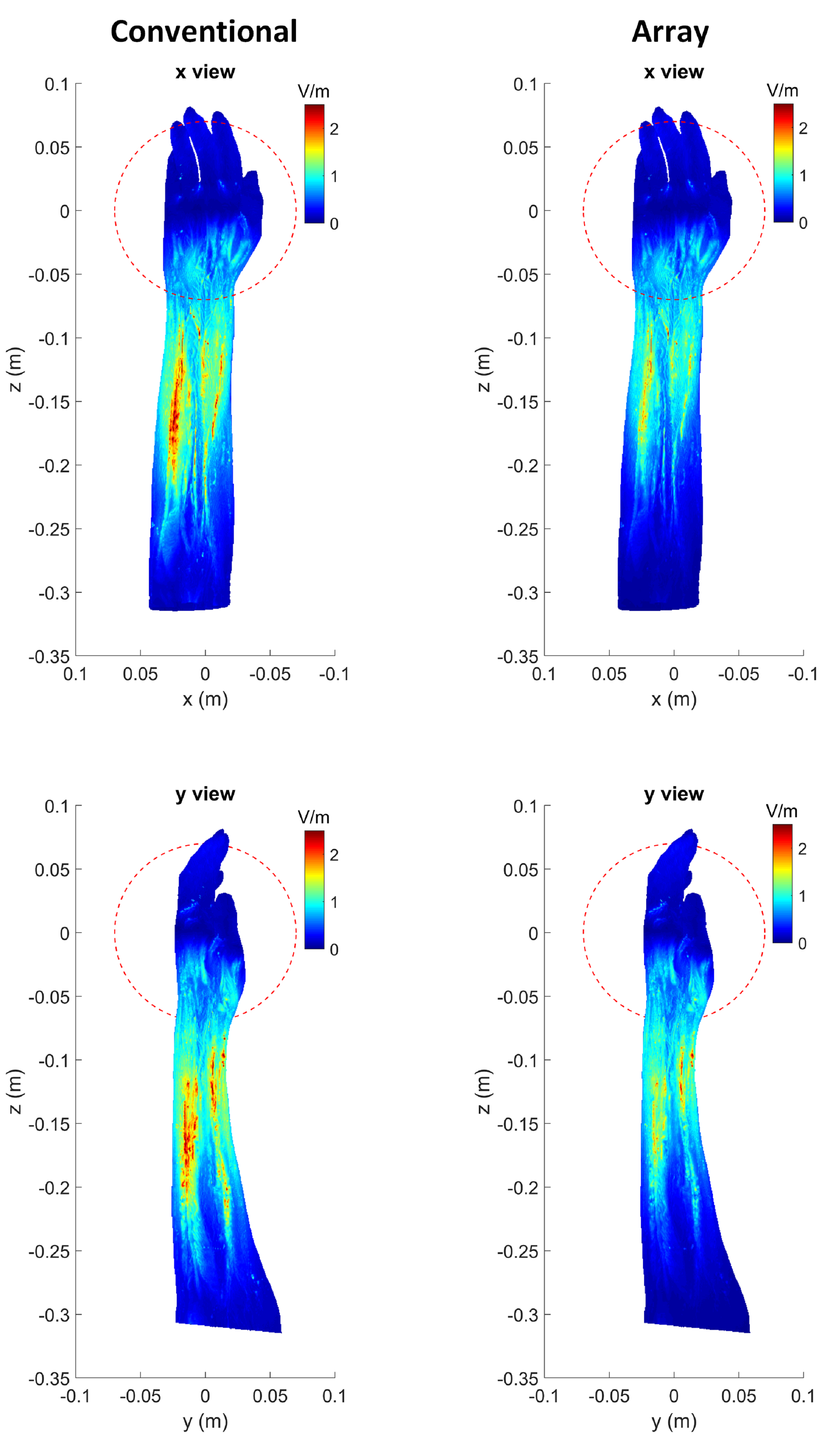
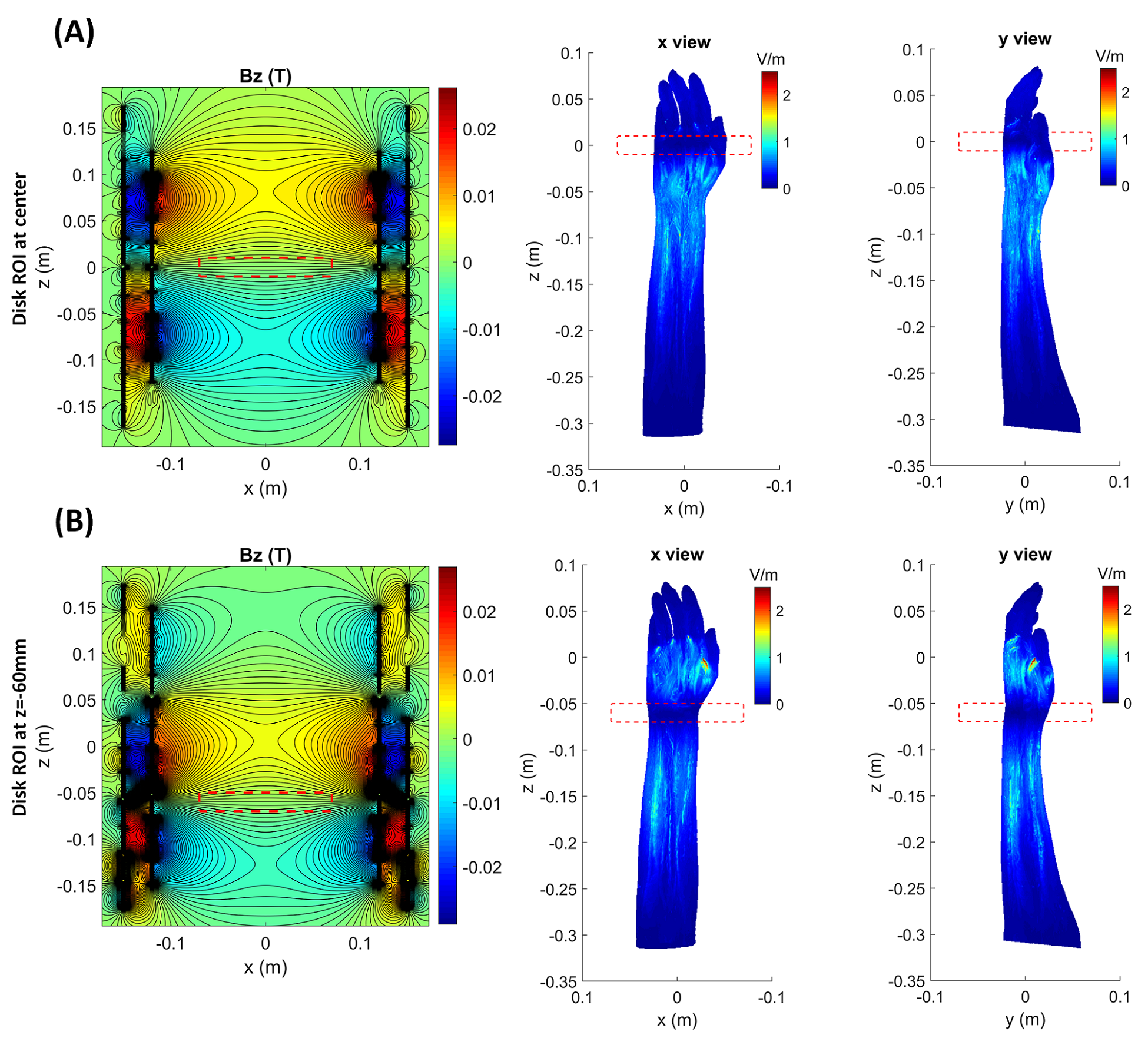
Magnetic field profile simulations for symmetric conventional and array gradient coils are shown in Figures 1C and 1D, respectively. In a spherical ROI (140mm diameter), both of these coils generate nearly 120 mT/m gradient strength, but the maximum magnetic field is lower in an array configuration. Since the arm model is not homogeneous, the maximum E-field may occur within the volume rather than on the surface. Therefore, we demonstrate the maximum intensity projection of E-fields. Figure 2 shows the E-fields of conventional and array gradient coils. Different patterns of array winding result in significantly reduced E-field magnitudes compared to the conventional one (for the same gradient B-field), allowing for higher PNS thresholds. Alternatively, at a constant maximum E-field for both coils, it is possible to achieve higher gradient strengths and slew rates with the array coil without hitting nerves. Figure 3 depicts the B-fields and maximum E-field projections for a disk-shaped ROI at isocenter and z=-60mm. Because array coils can generate dynamic gradient fields by optimizing feeding currents, ROI dimensions can be changed after the coil is manufactured. As shown in Figure 3, shrinking the ROI (gradient strength remains at 120mT/m) significantly reduces the maximum E-field, even when compared to the array coil's functionality in spherical ROI. Therefore, much higher gradients can be generated in a small ROI without exceeding PNS thresholds, promising for applications like diffusion-weighted imaging. Moving the disk to different positions alters the E-field maps and may result in some hotspots outsides of ROI, as they are visible in Figure 3B; however, this can be resolved by considering the E-field thresholds during the array coil design.Discussion
In this work, we compared E-field simulations of conventional symmetric and array gradient coils. The results indicate that the maximum E-field induced on the surface and inside of the arm model in the array configuration is much less than the maximum E-field induced by conventional coil, while the generated B-field profile and gradient strength are the same within the desired ROI. As a result, gradient array coils can be used with higher performances without surpassing PNS thresholds. The array design's ability to produce flexible magnetic fields also allows for different ROI sizes and shapes, resulting in further reduction in maximum E-field. Here, the array coil design and feeding currents optimization were performed subject to the gradient strength, ROI, and linearity error; however, adding the E-fields as a constraint to the optimization process will result in a PNS-optimized design.Acknowledgements
The authors acknowledge “Sim4Life by ZMT, www.zurichmeditech.com” for providing an Academic License.References
1. Zhang B, Yen YF, Chronik BA, McKinnon GC, Schaefer DJ, Rutt BK. Peripheral nerve stimulation properties of head and body gradient coils of various sizes. Magn Reson Med. 2003;50:50-58.
2. Tang F, Liu F, Freschi F, et al. An improved asymmetric gradient coil design for high-resolution MRI head imaging. Phys Med Biol. 2016;61:8875-8889.
3. Roemer PB, Wade T, Alejski A, McKenzie CA, Rutt BK. Electric field calculation and peripheral nerve stimulation prediction for head and body gradient coils. Magn Reson Med. 2021;86:2301-2315.
4. Davids M, Guerin B, Klein V, Wald LL. Optimization of MRI gradient coils with explicit peripheral nerve stimulation constraints. IEEE Trans Med Imaging. 2021;40:129-142.
5. Roemer PB, Rutt BK. Minimum electric-field gradient coil design: theoretical limits and practical guidelines. Magn Reson Med. 2021;86:569-580.
6. Ertan, K., Taraghinia, S., Sadeghi, A. and Atalar, E. (2018), A z‐gradient array for simultaneous multi-slice excitation with a single‐band RF pulse. Magn. Reson. Med, 80: 400-412.
7. Ertan, K, Taraghinia, S, Atalar, E. Driving mutually coupled gradient array coils in magnetic resonance imaging. Magn Reson Med. 2019; 82: 1187– 1198.
8. Babaloo, R., Taraghinia, S. Acikel, V., Takrimi, M., and Atalar, E. Digital Feedback Design for Mutual Coupling Compensation in Gradient Array System. Proceedings of the 28th Annual Meeting of ISMRM, 2020.
9. Takrimi, M. and Atalar, E. A Programmable Set of Z-Gradient Array and Active-Shield Array for Magnetic Resonance Imaging. Proceedings of the 28th Annual Meeting of ISMRM, 2020.
Figures