0578
RF Heating of Multi-channel icEEG Electrodes1Dept.of Radiology, Medical Physics, Medical Center University of Freiburg, Faculty of Medicine, University of Freiburg, Freiburg, Germany, 2CorTec GmbH, Freiburg, Germany
Synopsis
Active implantable medical devices restore body function in patients with neurological or other disorders, increasing their quality of life. The RF-safety assessment of neural implants is complex due to the increasing use of multi-channel systems. In this study, the heating characteristics of intracranial EEG electrodes with increasing number of channels is investigated. this study shows that, for the given configurations, the RF-induced heating decreases, when the number of channels of the device is increased. Hence, increasing the grids of planar electrodes might be used to decrease the RF induced heating.
Introduction
Active implantable medical devices (AIMDs) restore body function in patients with neurological or other disorders, increasing their quality of life. For diagnostic or therapeutic application of an AIMD, its precise localization is crucial. Especially in neurological AIMDs MRI is the preferred method for localization due to its excellent soft tissue contrast. Unfortunately, MRI might expose patients with an AIMD to a significant safety hazard1 during the exam as radio frequency (RF) fields can couple to the metallic structures of the AIMD resulting in potentially dangerous tissue heating.The safety assessment of neural implants is complex due to the increasing use of multi-channel systems (64-ch EEG grid, 120-ch cochlea implant). In these AIMDs, the close proximity of the lead wires can lead to electromagnetic coupling, changing the induced RF currents. Such effects need to be taken into consideration when designing MR safe implants. In this study, the heating characteristics of intracranial EEG electrodes with increasing number of channels is investigated using MR-thermometry and an electro optic sensor (EOS).
Methods
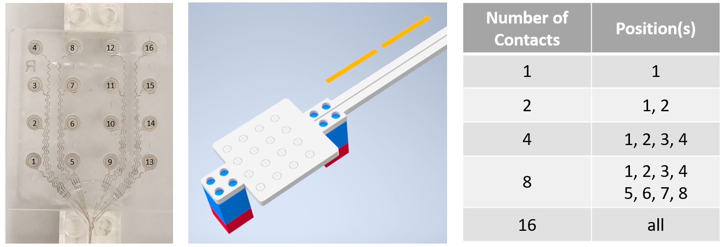
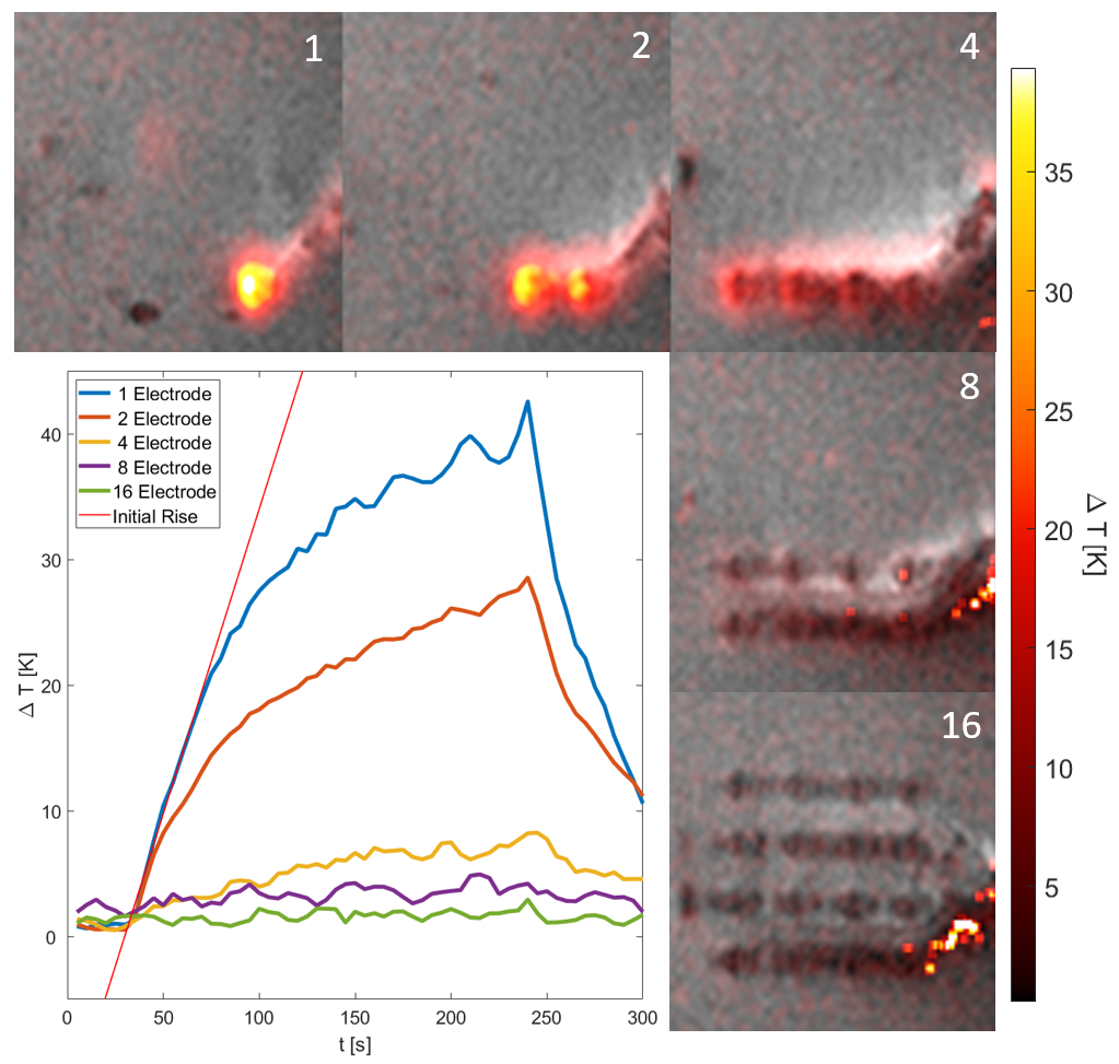
Cortical grid electrodes with a 4x4 layout were manufactured (CorTec GmbH, Freiburg, Germany) from 25$$$\,$$$µm Pt90/Ir10 foil$$$\,$$$(Fig.1). Each electrode contact was connected via meandered tracks to a 30$$$\,$$$cm$$$\,$$$-$$$\,$$$long Pt90/Ir10-cable. In total five grids were manufactured with n$$$\,$$$=$$$\,$$$[1,$$$\,$$$2,$$$\,$$$4,$$$\,$$$8,$$$\,$$$16] channels$$$\,$$$(Fig.1). The grids were fixed on acrylic-glass sample holders and placed in a 15x15x50$$$\,$$$cm3 phantom filled with HEC gel2 (31$$$\,$$$g/L hydroxyelthycellulose, 1.55$$$\,$$$g/L NaCl).To assess RF-induced heating, the setup was placed in a clinical 3T MRI system (MAGNETOM Trio, Siemens Healthineers) with the leads parallel to B0 at an off-isocenter position (Δx=21cm). Temperature changes were induced and measured by a proton resonance frequency (PRF) thermometry sequence3 with an off-resonant RF pulse for heating4. The following parameters were used: TE/TR$$$\,$$$=$$$\,$$$10/21$$$\,$$$ms, αimaging$$$\,$$$=$$$\,$$$10°, αheating$$$\,$$$=$$$\,$$$200°, 1x1x2$$$\,$$$mm3 resolution, TA$$$\,$$$=$$$\,$$$4.9$$$\,$$$s, nominal whole body SAR: 4$$$\,$$$W/kg. Five baseline images were acquired followed by 50 images with heating pulses, and 10 images without the heating pulses to visualize the cool-down. The lower bound of the PRF imaging slice was placed 2$$$\,$$$mm above the electrodes. Temperature change maps were calculated from the incremental differences between phase maps.
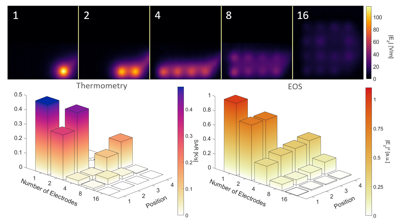
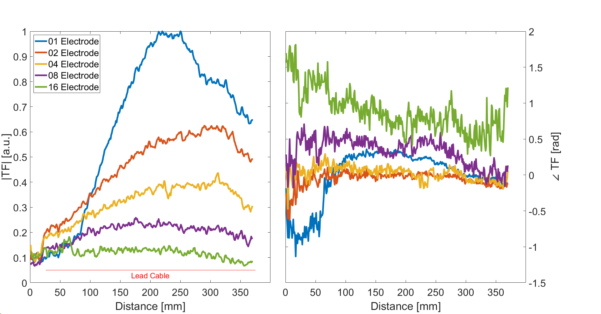
The same samples were investigated using an EOS5. The electrode grid was excited with a dipole antenna positioned parallel to the lead wires, while the resulting scattered electric field was recorded above the electrode contact sites. The EOS was moved by a 2D translation stage to generate planar field maps and one field map was acquired in 2-8 minutes depending on the number of contact sites present. Additionally, the transfer function was measured for all five grids using the EOS: A localized tangential electric field source was used to excite the lead cable and moved in subsequent measurements by a 5mm increment. The resulting scattered field was then recorded with the EOS above contact site 1$$$\,$$$(Fig.1) as the TF of that contact site.
Results
Maximum temperature elevation in the PRF heating experiment was ΔTmax$$$\,$$$=$$$\,$$$42.1$$$\,$$$K for the single electrode. Heating was concentrated at the uninsulated contact site of the electrode, where metal and the phantom gel were in direct contact. With increasing number of electrodes, the maximum temperature difference decreases$$$\,$$$(Fig.2) by up to 96% between the single electrode and the full 16-channel grid. The same trend wass observed in the EOS measurements. The average SAR above the contact sites decresaes with increasing number of electrode channels$$$\,$$$(Fig.3) by up to 94%. Also, an increase in heating/SAR with increasing meandering track length is also visible. The TFs of contact site 1 showed a decrease in magnitude and a shift in the maximum of the TF$$$\,$$$(Fig.4).Discussion & Conclusion
MR thermometry allowes the localization of the temperature hotspot in the complex AIMD geometry. However, using PRF MR Thermometry thermal, spatial and temporal resolution cannot be optimized simultaneously. Furthermore, studies are highly sensitive to the exact positioning inside the MRI, due to the complex incident RF field of the body resonator. EOS measurements on the other hand offer a high sensitivity for electric fields and submillimeter spatial resolution. The incident field along the wires can be characterized either by a well-known source like the dipole antenna or by measuring the TF.This study shows that the response of the implant to an incident electric field decreases with the number of channels. This in turn reduces the RF-induced heating significantly. The transfer function measurements show the cross-coupling between the channels affects the response to excitation and hence the channels cannot be investigated individually. With increasing number of electrodes the surface (and the volume) of the region of the AIMD in contact with the tissue also increases such that the induced energy is distributed over a larger volume. Additionally, the presence of additional cables will change the RF behavior of the leads by changing the resonance of the system as well as its response to an incident field along the lead wire(s). Overall, this study shows that, for the given configurations, the RF-induced heating decreases, when the number of channels of the device is increased. Hence, increasing the grids of planar electrodes might be used to decrease the RF induced heating. This could be useful in the design of these devices and support efforts to establish MR compatibility.
Acknowledgements
No acknowledgement found.References
1. Winter L, Seifert F, Zilberti L, Murbach M, Ittermann B. MRI-Related Heating of Implants and Devices: A Review. J. Magn. Reson. Imaging 2021. doi: 10.1002/jmri.27194.
2. American Society for Testing and Materials International. Designation: ASTM F2182-11a, standard test method for measurement of radio frequency induced heating near passive implants during magnetic resonance imaging. West Conshohocken, PA; 2011.
3. Ehses P, Fidler F, Nordbeck P, Pracht ED, Warmuth M, Jakob PM, Bauer WR. MRI thermometry: Fast mapping of RF-induced heating along conductive wires. Magn. Reson. Med. [Internet] 2008;60:457–461. doi: 10.1002/mrm.21417.
4. Quesson B, De Zwart JA, Moonen CTW. Magnetic resonance temperature imaging for guidance of thermotherapy. J. Magn. Reson. Imaging 2000;12:525–533. doi: 10.1002/1522-2586(200010)12:4<525::AID-JMRI3>3.0.CO;2-V.
5. Reiss S, Bitzer A, Bock M. An optical setup for electric field measurements in MRI with high spatial resolution. Phys. Med. Biol. 2015;60:4355–4370. doi: 10.1088/0031-9155/60/11/4355.
Figures