0577
Field orientation matters: vertical open-bore scanners significantly reduce RF heating around implanted deep brain stimulation devices1Biomedical Engineering, Northwestern University, Evanston, IL, United States, 2Radiology, Northwestern University, Chicago, IL, United States, 3Illinois Bone and Joint Institute, Wilmette, IL, United States, 4Neurosciences & Experimental Therapeutics, Albany Medical College, Albany, NY, United States, 5Neurosurgery, Northwestern University, Chicago, IL, United States
Synopsis
Radiofrequency (RF) heating of tissue around active electronic implants limits MRI accessibility for patients with deep brain stimulation (DBS) devices. Here, we show that RF heating had an 11-fold reduction on average for a DBS device with clinically relevant, patient-derived lead trajectories during MRI in a 1.2 T vertical scanner compared to a 1.5 T horizontal scanner. Electromagnetic simulations showed up to a 14-fold decrease in the maximum of the 0.1g-averaged SAR, which was consistent in leads with various internal wire geometries/electrical lengths, suggesting that our experimental results could potentially generalize to DBS devices from other manufacturers.
Introduction
Radiofrequency (RF) heating of tissue is a well-known safety risk when an active electronic implant is present during an MRI exam1-4. Current deep brain stimulation (DBS) device guidelines restrict scanning outside of horizontal field, closed-bore scanners5-7. Vertical, open-bore MRI systems have a 90° rotated magnet and a fundamentally different RF coil geometry which generates a substantially different field distribution in the human body8,9. We present the first experimental results of RF heating of a commercial DBS device with realistic trajectories in a vertical scanner compared to a horizontal scanner which demonstrated significantly reduced heating in the open bore system. Results were further augmented by electromagnetic (EM) simulations which also showed substantially reduced specific absorption rate (SAR) in the open bore system. SAR reduction was consistent across leads of different geometries, suggesting that our results can potentially extend to leads from other manufactures.Methods
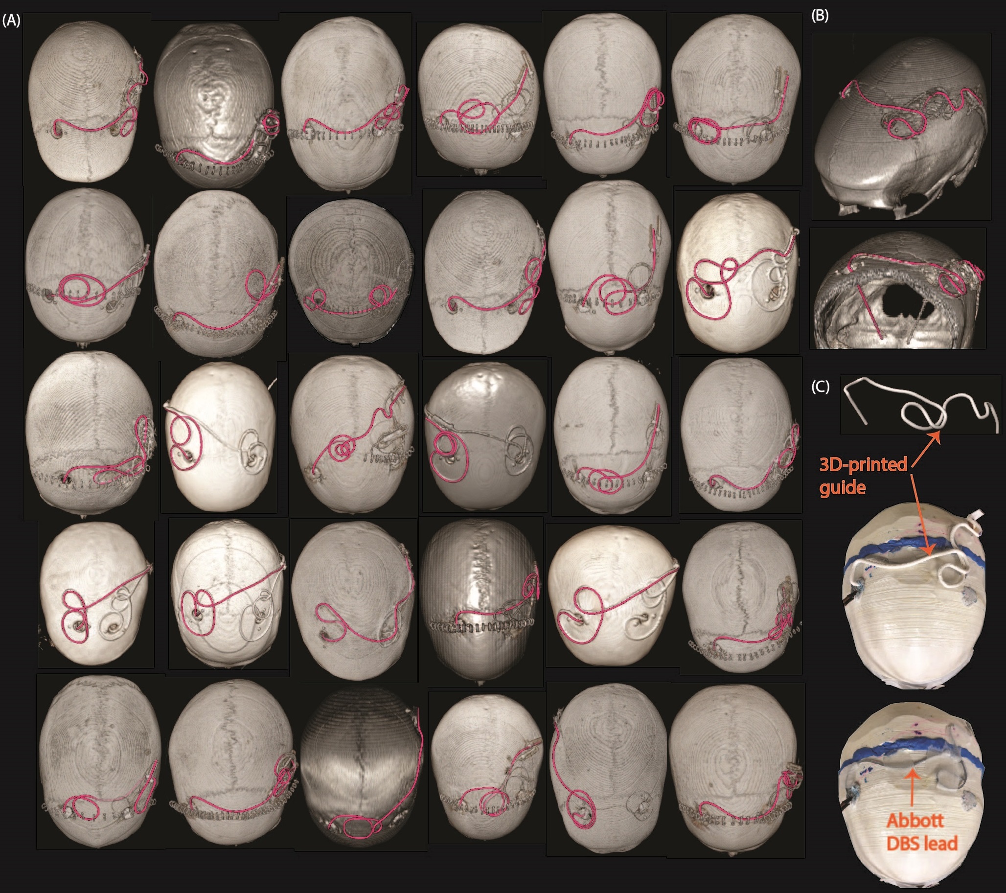
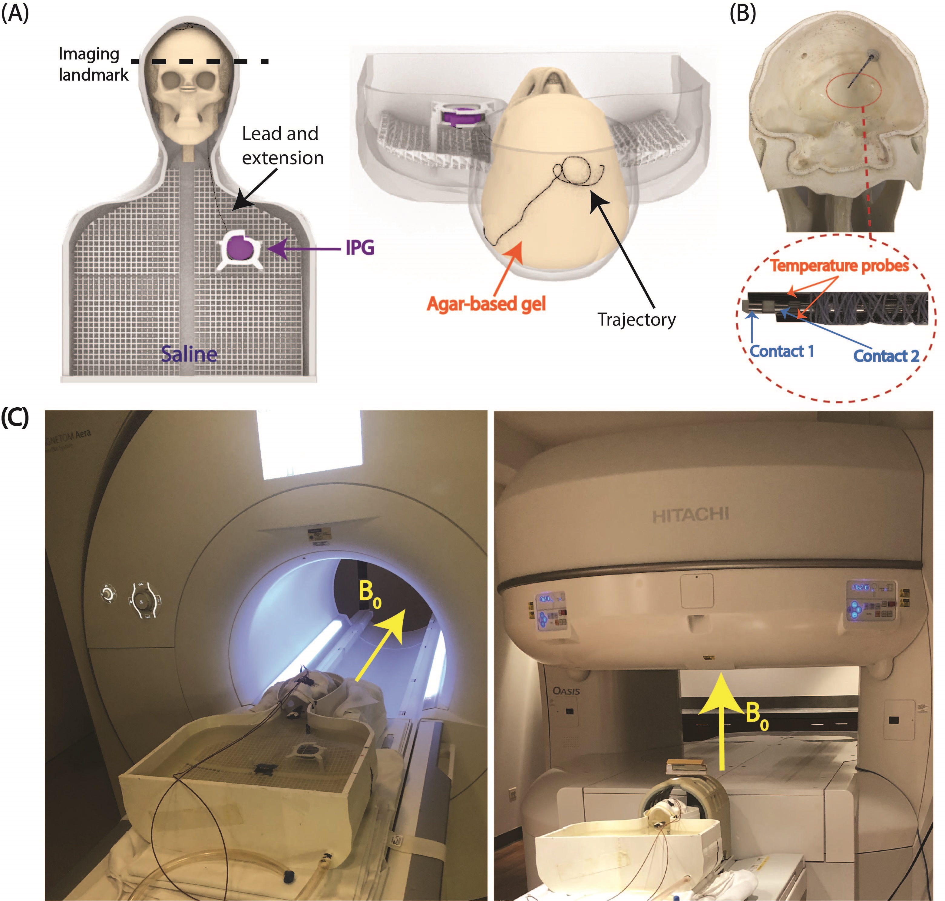
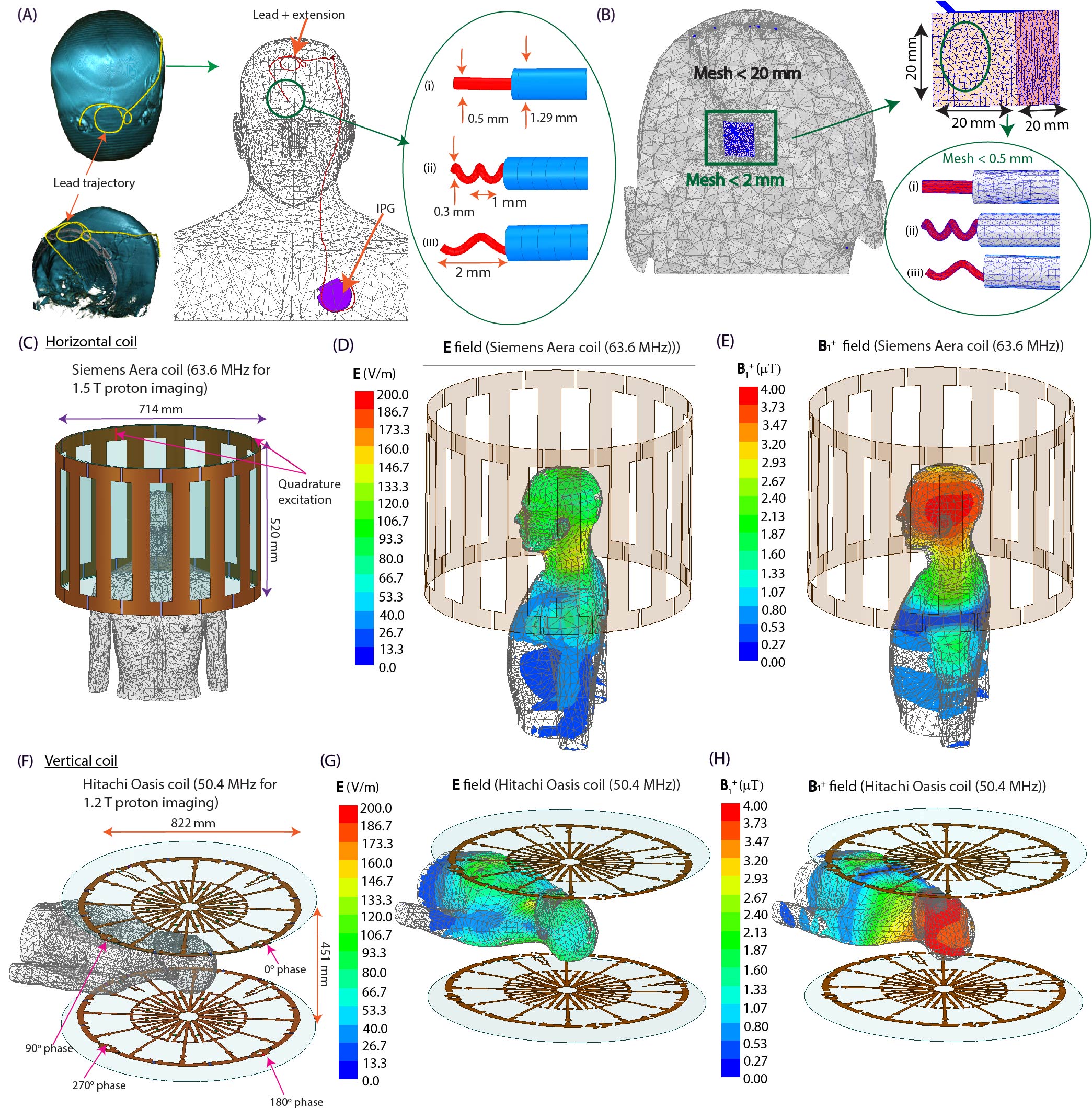
Experiments: Thirty unique DBS lead trajectories were extracted from postsurgical computed tomography (CT) images of patients who underwent DBS surgery at Northwestern Memorial Hospital and Albany Medical Center (Figure 1). Lead trajectories were manually segmented from CT images to create realistic device configurations which were replicated in an anthropomorphic phantom. A commercial DBS system from Abbott (Abbott Medical, Plano, TX) consisting of a 40 cm lead (model 6173), a 50 cm extension (model 6371), and an implantable pulse generator (IPG) (Infinity 6660) was used in all experiments. The DBS system was implanted in a multi-material, anthropomorphic phantom; the skull was filled with a brain tissue mimicking agar-based gel (σ=0.40 S/m, εr=79, and thermal conductivity of 0.56 J/K-S) while the remaining head-torso component of the phantom was filled with 18 L of saline solution (σ=0.50 S/m) to mimic the conductivity of average tissue (Figure 2). The DBS lead was inserted into the skull with fluoroptic temperature probes securely attached to measure the maximum temperature increase (∆𝑇max) at the lead-tip. RF exposure was generated using high-SAR turbo spin echo and fast spin echo sequences such that the B1+rms was 4 μT and the acquisition time was 224 seconds at both scanners.Simulations: EM simulations were performed to evaluate the effect of the lead’s length and internal structure on RF heating. Simulations were implemented in ANSYS Electronic Desktop 2021 R1 HFSS. A trajectory that resulted in a large difference in ∆𝑇max between the horizontal versus vertical scanners was modeled. The lead and extension consisted of a core wire made of platinum-iridium (σ=4x10⁶ S/m) embedded within a urethane insulation (σ=0 S/m, εr=3.5). The total length of the modeled lead and extension was 90 cm to match the commercial device used during experiments; however, the electrical length of the core wire was changed by modeling either a straight wire (electrical length=90 cm) or helical wires with pitches of 1 mm (electrical length=171 cm) and 2 mm (electrical length=116 cm) (Figure 3). A numerical model of a high-pass, radial planar 12-rung birdcage coil tuned to 50.4 MHz with the specifications provided by the vendor of the vertical scanner was constructed9. Similarly, a high-pass 16-rung horizontal birdcage coil tuned to 63.6 MHz was constructed based on the details provided by the vendor of the horizontal scanner. The input voltage applied to each coil was adjusted to generate a mean B1+ of 4 μT on a transverse plane at the center of the coil.
Results
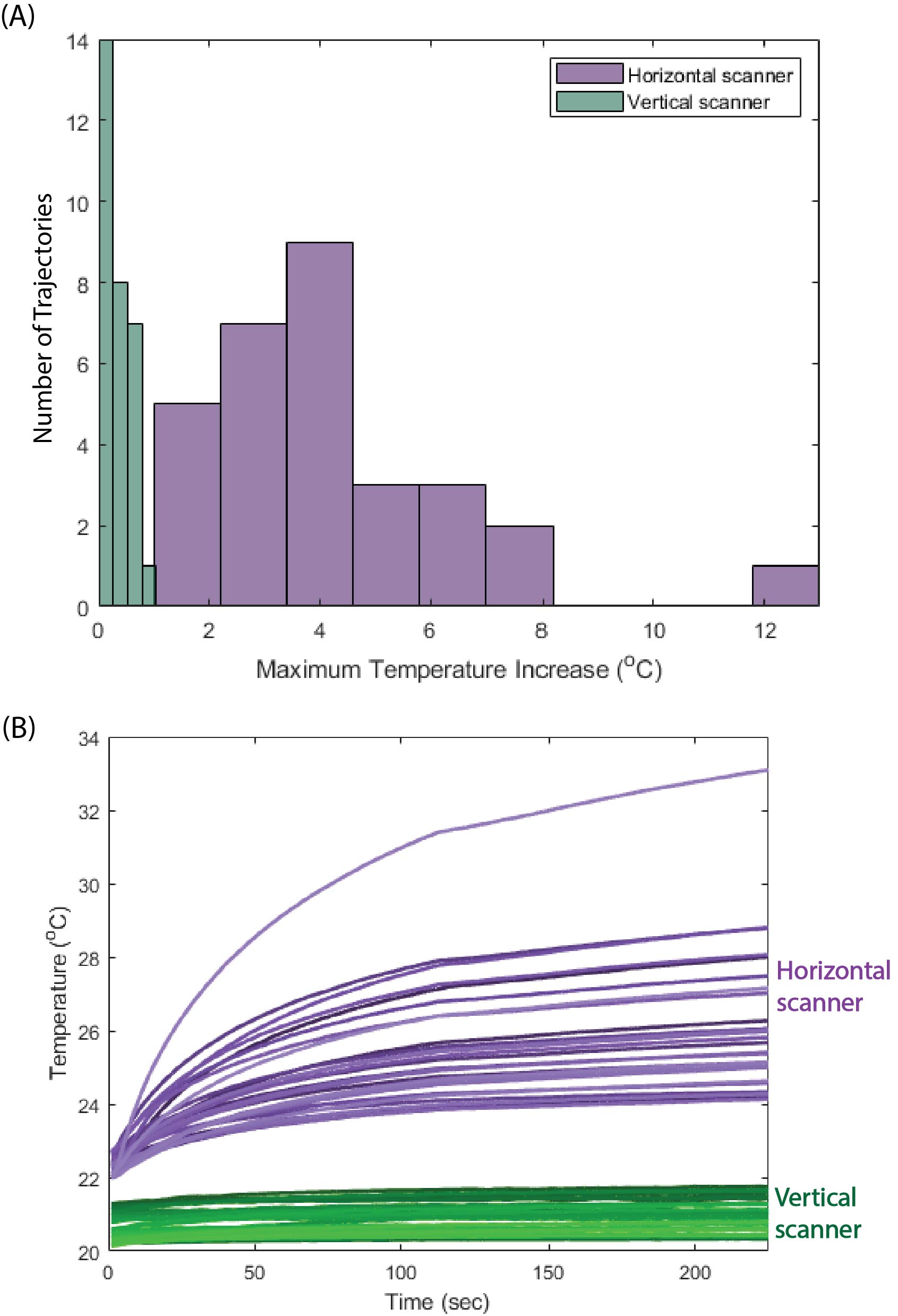
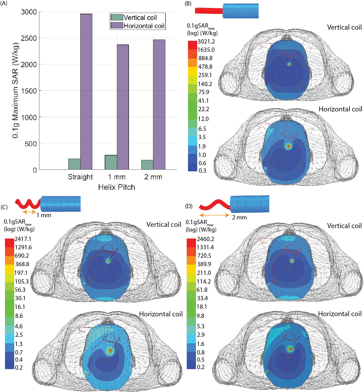
RF exposure at the vertical scanner generated a ∆𝑇max of 0.04–1.01 °C with a mean ± standard deviation of 0.36±0.24 °C while ∆𝑇max was 1.84–12.92 °C at the horizontal scanner with a mean ± standard deviation of 4.19±2.29 °C (Figure 4). A one-tail Wilcoxon signed rank test showed that ∆𝑇max was significantly lower in the vertical scanner compared to in a conventional horizontal scanner (p=9.1 x 10⁻⁷).The power deposition in the tissue around the DBS lead-tip, indicated by the 0.1g-averaged SAR (0.1gSARmax), was quantified in simulations of the lead and extension represented with different structures of the core wire. With a mean B1+=4 μT, 0.1gSARmax was consistently lower for the 1.2 T vertical coil compared to the 1.5 T horizontal coil across all internal structures of the lead. Figure 5 shows the distribution of 0.1gSARmax on an axial plane intersecting the DBS lead-tip. The mean ± standard deviation of 0.1gSARmax was 220.4±48.3 W/kg and 2593.4±312.3 W/kg for the vertical and horizontal coils, respectively.
Discussion and Conclusion
We presented the first experimental results showing that RF heating of a full commercial DBS system with realistic trajectories was significantly reduced during imaging at the 1.2 T vertical scanner compared to the 1.5 T horizontal scanner for all 30 patient-derived device configurations. For a high SAR sequence (B1+rms=4 μT), temperature increase was well below 2 °C for all trajectories at the vertical scanner whereas ∆𝑇max up to 12°C was recorded at the horizontal scanner. EM simulations demonstrated that maximum SAR was substantially reduced in the vertical coil compared to the horizontal coil across different geometries of the internal wire of the DBS lead, indicating that such reduction in RF heating may be possible for other commercial DBS systems where the total electrical length of the lead varies from the one that we experimented with.Acknowledgements
This work was supported by NIH grants R03EB029587and T32EB025766.References
1. Rezai AR, Phillips M, Baker KB, et al. Neurostimulation system used for deep brain stimulation (DBS): MR safety issues and implications of failing to follow safety recommendations. Investigative radiology. 2004;39(5):300-3.
2. Golestanirad L, Angelone LM, Iacono MI, et al. Local SAR near deep brain stimulation (DBS) electrodes at 64 and 127 MHz: A simulation study of the effect of extracranial loops. Magn Reson Med. 2017;78:1558–65.
3. Golestanirad L, Kirsch J, Bonmassar G, et al. RF-induced heating in tissue near bilateral DBS implants during MRI at 1.5 T and 3T: The role of surgical lead management. Neuroimage 2019;184:566–76.
4. Bhusal B, Nguyen BT, Sanpitak PP, et al. Effect of Device Configuration and Patient’s Body Composition on the RF Heating and Nonsusceptibility Artifact of Deep Brain Stimulation Implants During MRI at 1.5T and 3T. J Magn Reson Imaging. 2020;53(2):599-610.
5. MRI guidelines for Medtronic deep brain stimulation systems, 2020.
6. Boston Scientific. ImageReady MRI Guidelines for Boston Scientific Deep Brain Stimulation System, 2021.
7. Abbott Medical. MRI procedure information for Abbott Medical MR conditional deep brain stimulation system, 2020.
8. Golestanirad L, Kazemivalipour E, Lampman D, et al. RF heating of deep brain stimulation implants in open‐bore vertical MRI systems: A simulation study with realistic device configurations. Magn Reson Med. 2020; 83(6):2284-92.
9. Kazemivalipour E, Bhusal B, Vu J, et al. Vertical open‐bore MRI scanners generate significantly less radiofrequency heating around implanted leads: A study of deep brain stimulation implants in 1.2 T OASIS scanners versus 1.5 T horizontal systems. Magn Reson Med. 2021;86(3):1560-72.
Figures