0363
Advances in short-wave motion tracking: Jaw-mount markers and prospective motion correction
Christoph Michael Schildknecht1, David Otto Brunner1, Thomas Schmid1, and Klaas Paul Prüssmann1
1Institute for Biomedical Engineering, ETH Zurich and University of Zurich, Zürich, Switzerland
1Institute for Biomedical Engineering, ETH Zurich and University of Zurich, Zürich, Switzerland
Synopsis
Prospective motion correction has demonstrated significant value for human brain MRI. One issue that all marker-based motion trackers share is the marker fixation to the human head. Short-wave motion tracking can solve this issue since the small wireless marker can directly be attached to the upper jaw with the mouth completely closed. In this work, we present PMC in-vivo imaging with such a sensor. The high temporal and spatial resolution can be observed in the measured physiological motion trajectories, illustrating the high-quality motion of this sensor.
Introduction
Prospective motion correction (PMC) has demonstrated significant value in human brain MR imaging1. While there exist many different modalities for acquiring the motion trajectories of the human head, none of them had proven to be a solution for all cases2. Especially since a marker is required for robust and high-quality motion tracking, its fixation on the human head remains a big issue. A possible solution to this marker fixation issue was recently introduced as short-wave motion tracking3,4. In short-wave motion tracking, the frequency band in the range of 1-5 MHz is utilized where commonly found materials such as human tissue and plastics are transparent. This enables a marker to be directly attached to the upper jaw, which is grounded in the skull. Because short-wave permeates human tissue, the patient can keep the mouth closed in a relaxed state. Further, this frequency range is not occupied by the scanner, and therefore the tracking can happen independently from the scanner. No coordination with the scanner sequence and timing has to be considered.In this work, we demonstrate in-vivo prospective motion correction in a 3T system with such a short-wave tracker.
Methods
The utilized short-wave motion tracking system operates by measuring reflected oscillating magnetic fields from a marker as described in the previous publications3,4. The utilized system is configured for 480 samples per second (SPS) and has a noise of 0.24μm/sqrt(Hz) and 0.74mdeg/sqrt(Hz).As shown in Fig. 1, the marker includes the fixation to the upper jaw and is 3D printed out of a biocompatible resin (“BioMed Clear”, Formlabs). The material is UPS class iv certified and sterilizable. After putting the reflector windings into the marker, they were potted with the same resin. To fixate the marker to the upper jaw, one has to push the holder onto the upper jaw, which then locks firmly in place. After that, the subject does not need to do anything to hold it in place during the MRI examination.
The MRI measurements were done on a Philips 3T Achiva system. In Fig. 2, a static phantom measurement is was made, where one slice is measured for one hour with and without PMC to evaluate the image degradation of PMC due to sensor noise and other effects. For in-vivo imaging, a PMC comparison of a 2D multislice SPGR with T2* weighted without deliberate motion was made and shown in Fig. 3. With instructed motion, a comparison of PMC with a 3D MPRAGE sequence was performed and shown in Fig. 4. There the volunteer was asked to roll around the FH axis.
In Fig. 5, a snipped of the motion parameters from the measurement without deliberate motion is displayed, as shown in Fig. 3.
Results
The phantom measurement from Fig. 2 shows no indication of image degradation due to the active PMC. The estimated motion from the sensor was around 5μm and 5mdeg during the 60min scan.The in-vivo measurement without deliberate motion, as shown in Fig. 3, shows image degradation in the measurement without PMC. With PMC enabled, the T2* images are pristine. The measurement of Fig. 4, with instructed motion, resulted in no significant image degradation when PMC was enabled. Without PMC, the images have reduced quality.
In Fig. 5 can the physiological motion of the volunteer be seen. No interference from the scanner can be seen, and even tiny details are spatially and temporally resolved.
Discussion and conclusion
Given the static phantom experiment, one would expect that sensor noise would decrease the effective resolution, which would show up as a double edge in the difference image. No such distinct feature can be seen, which is no surprise since the noise was in the lower single-digit micrometre and millidegrees.The T2* images with no deliberate motion have not much to complain about when PMC was enabled, given the limitation of a 3T system. Granted, the motion during the PMC scan was approximately half the reference, but it would still result in significant image degradation without functioning PMC. The MPRAGE images illustrate that PMC functions properly under motion as expected.
The rich physiological motion could be valuable beyond PMC. For example, for FMRI as additional regressors, for respiratory gating or for cardiac gating. Another exciting application, enabled by the high temporal and spatial resolution, would be to correct the motion during diffusion encoding gradients where micrometre motion results in meaningful phase errors.
The overall PMC performance is most certainly not limited by the short-wave sensor. It is believed that the scanner latency for PMC updates and that only every TR one update is applied is limiting the performance. A possible solution would be to combine retrospective correction with PMC5,6.
Acknowledgements
No acknowledgement found.References
- Maclaren, J., Herbst, M., Speck, O. & Zaitsev, M. Prospective motion correction in brain imaging: A review. Magnetic Resonance in Medicine 69, 621-636, doi:10.1002/mrm.24314 (2013).
- Zaitsev, M., Maclaren, J. & Herbst, M. Motion artifacts in MRI: A complex problem with many partial solutions. Journal of Magnetic Resonance Imaging 42, 887-901, doi:10.1002/jmri.24850 (2015).
- Schildknecht, C. M., Brunner, D. O., Schmid, T. & Pruessmann, K. P. Design considerations for short-wave motion tracking. Proc. Intl. Soc. Mag. Reson. Med. 28 (2020).
- Schildknecht, C. M. et al. Wireless motion tracking with short-wave radiofrequency. Proc. Intl. Soc. Mag. Reson. Med. 27 (2019).
- Aksoy, M. et al. Hybrid prospective and retrospective head motion correction to mitigate cross-calibration errors. Magnetic Resonance in Medicine 67, 1237-1251, doi:10.1002/mrm.23101 (2012).
- Norbeck, O. et al. T 1 ‐FLAIR imaging during continuous head motion: Combining PROPELLER with an intelligent marker. Magnetic Resonance in Medicine 85, 868-882, doi:10.1002/mrm.28477 (2021).
Figures
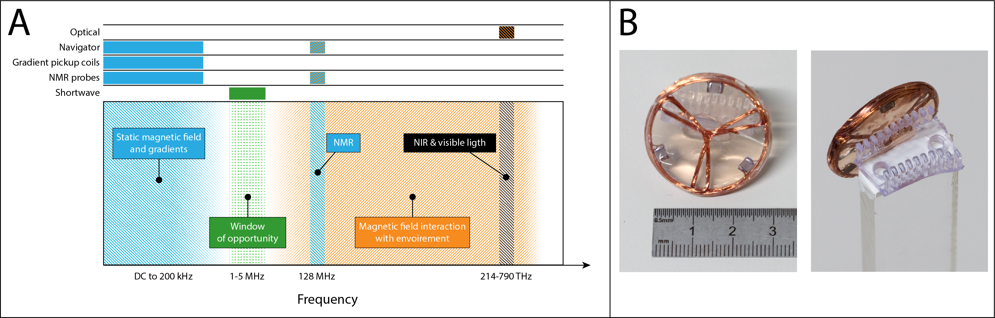
In
section A, the frequency spectra inside an MRI scanner is shown. In blue are
the bands occupied by the scanner, and the orange section denotes the region where
the field interact with human tissue and other materials. It is desired for independent
and robust motion tracking to avoid both regions, as it is achieved in the 1-5
MHz band. In section B is an example of a marker show that can be directly
mounted to the upper jaw.
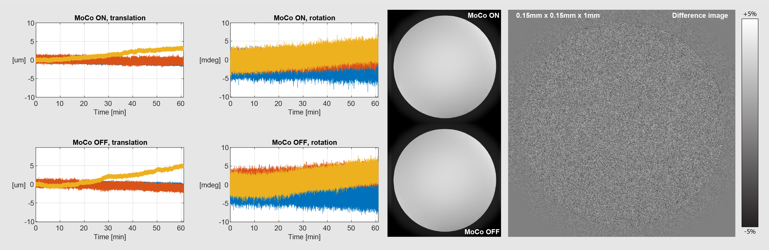
Shown here is the result of phantom imaging with
and without PMC of a static phantom with a marker attached. When taking the
difference between the two images as shown on the right, no conspicuous
features can be seen, even when scaling the difference image to a range of +-5%
of the total amplitude. Scan parameters were 0.15 x 0.15 x 1mm with 120
averages. Scan time was 60min, TR was 20.6 ms, TE 10.26 ms and flip angle 58.8
deg. On the left are the motion parameter of those scans shown.
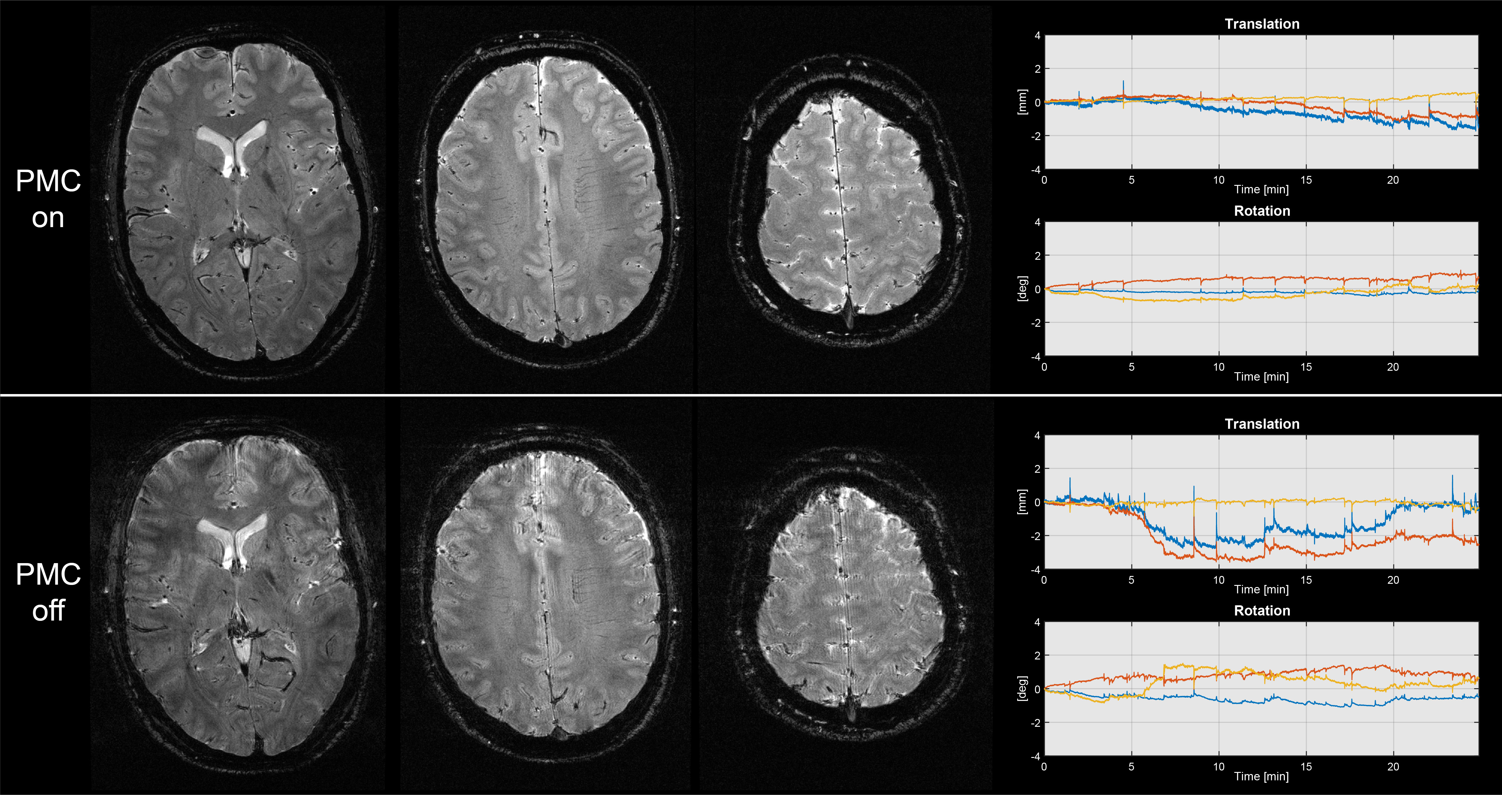
Shown here are two measurements without
deliberate motion, one with and the other without PMC. The imaging sequence was
a T2* 2D SPGR with 0.5 x 0.5 x 1.5mm resolution and a TR of 1100 ms, TE of 39.1
ms and a flip angle of 66 degrees. The total scan time was 24min and 52sec per
measurement.
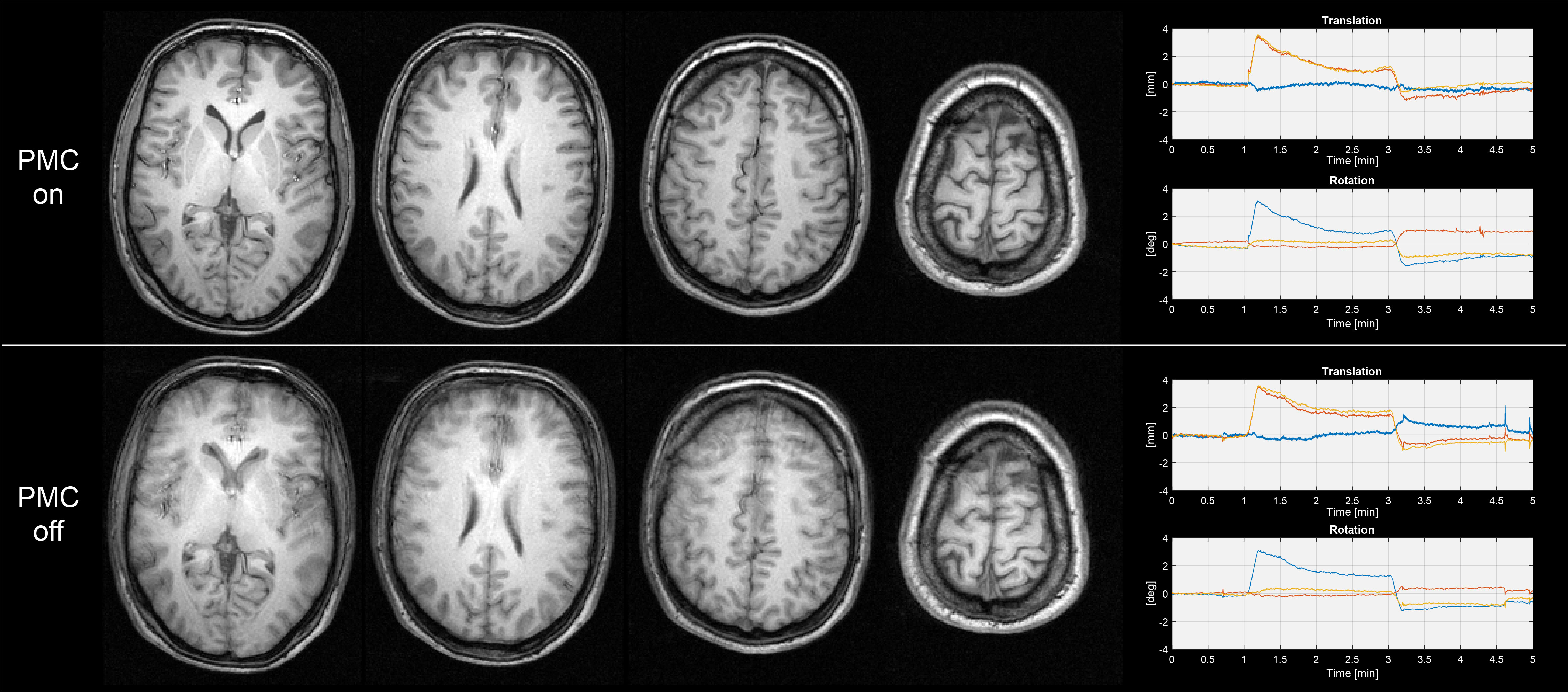
Shown here are two measurements, one with and
the other without PMC, where the volunteer was asked to roll around the FH axis
after one minute and roll back after three minutes. The sequence was a 3D
MPRAGE with 1 x 1 x 1.5mm resolution and a TR of 8.5ms, TE of 4.1 ms, Ti of
900ms and a flip angle of 8 degrees. The scan time per measurement was 5min and
6sec.
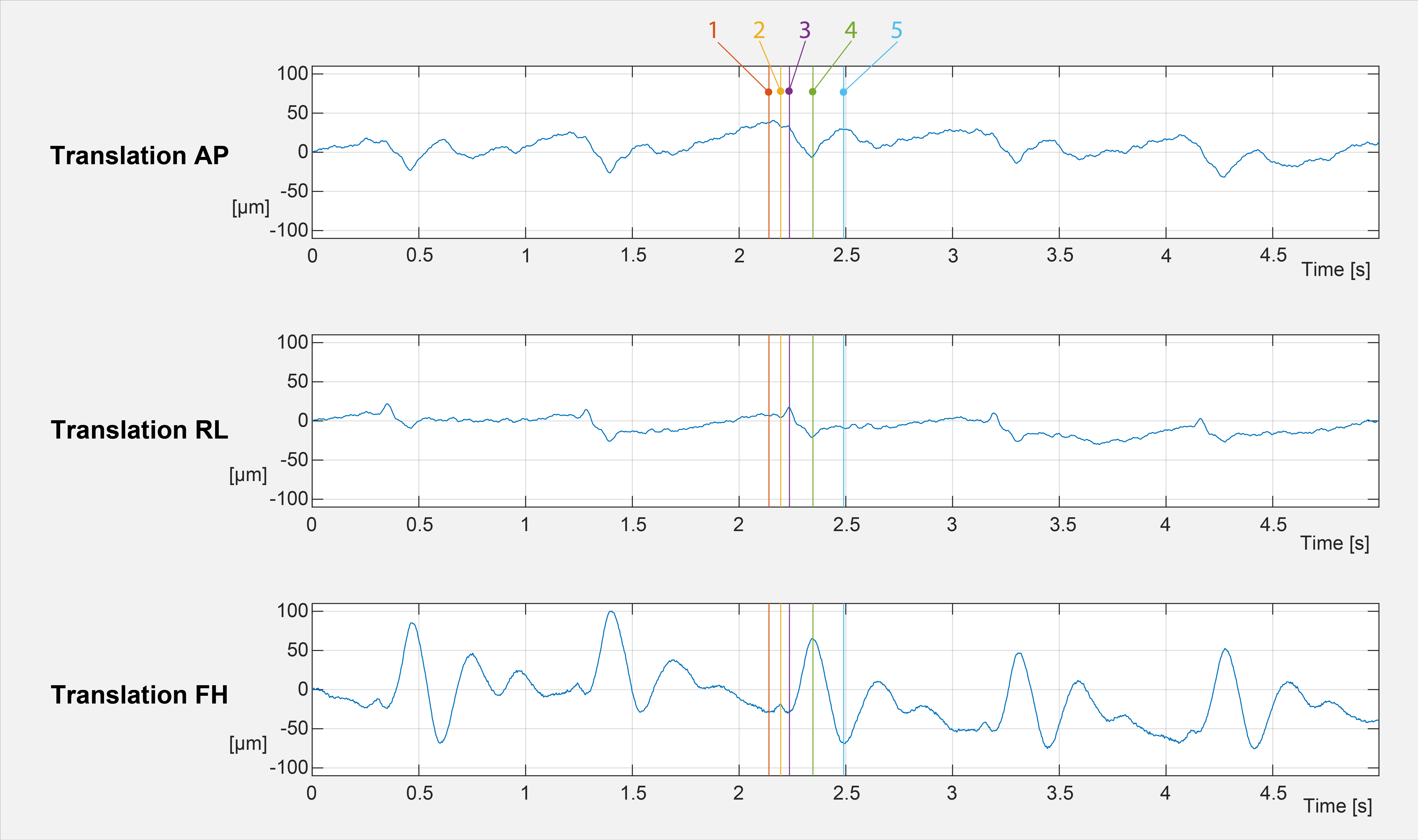
Shown
here are the zoomed-in motion trajectories from the T2* measurement, as shown in
Fig. 3. The temporal resolution is around 480 samples per second. Despite the
high bandwidth, tiny movements are well depicted. The colour markers 1-5 are mark
interesting time points in the cardio ballistic head motion. For example, each
time before the prominent peak with marker nr. 4, a slight movement of
approximately 10μm is
happening between markers 1 and 2 in the FH direction.
DOI: https://doi.org/10.58530/2022/0363