0350
Prospective motion correction for 2D T1-Mapping in the liver using an ultra-wideband radar system1Physikalisch-Technische Bundesanstalt, Braunschweig and Berlin, Germany, 2Siemens Healthcare, Erlangen, Germany
Synopsis
We present a radar-based approach for prospective motion correction for 2D T1 mapping of the abdomen. An ultra-wideband radar signal is acquired simultaneously but otherwise completely independent of the MR measurement. This allows us to correct for in-plane as well as through-plane motion during MR acquisition. This is especially important for 2D T1 mapping, where motion can cause not only blurring and streaking artifacts, but also inaccurate values when unexcited volumes move through the recorded image plane. It is demonstrated that the method strongly improves T1 maps in phantom and in-vivo scans.
Introduction
T1 mapping has been shown to be a powerful tool for the diagnosis of tumors in the liver[1,2]. One of the main challenges is the livers respiratory motion. Especially for 2D mapping in different orientations the breathing displacement of the liver can cause severe through plane motion which cannot be corrected for retrospectively. Prospective corrections such as slice tracking are required[3]. Commonly this is carried out using an MR-based navigator placed on the dome of the liver. Nevertheless, this would interfere with the imaging sequence and would not allow for accurate T1 quantification where the navigator has been acquired.Here we present a prospective motion correction approach for 2D T1 mapping using an ultra-wideband (UWB) radar signal as a motion surrogate[4]. The radar signal is contactless and does not interfere with the MR data acquisition. After a calibration step, the radar signal can be used to adapt the slice position in real-time and allow for 2D T1 mapping during free-breathing. The approach showed improved T1 maps in phantoms and in-vivo scans.
Methods
In a first calibration step, the radar signal is acquired simultaneously with a dynamic MRI scan. A region of interest (ROI) (e.g. a tumor) is selected and a linear motion model between radar signal and the ROI is created. In a second step the motion model and the current radar signal are used to adapt the slice position in real-time to compensate for respiratory motion during the T1 mapping sequence.Radar signal
We used an inhouse-developed radar system. The signal was generated with a m-sequence baseband module (MEODAT GmbH) and transmitted by a double-ridged horn antenna. Two antennas identical to the first were used to receive the radar response. A cross-correlator generated an impulse response from the transmitted and received signals[5]. Every 22.6ms the system creates a radargram with 511 data points each with a time step of 111ps. This offers the required temporal resolution to accurately track breathing processes.
Motion-model calibration
During calibration radar signals were continuously recorded while simultaneously acquiring MR images. A ROI was selected (a blood vessel in our healthy subjects scanned here, ultimately a tumor or suspicious lesion in patients) and rigid image registration of the ROI over time was carried out. The principal component of the radar signal was correlated with the registered motion from the MR images and two linear motion models were derived for anterior-posterior and head-feet motion.
Motion correction
During the T1 mapping scan, the real-time radar signal and the calibrated motion model were used to predict and correct for the respiratory motion of the selected ROI.
MR scan parameters
All scans were performed using inhouse-developed sequences and reconstructions on a 3T system (MAGNETOM Verio, Siemens Healthineers, Erlangen, Germany). A 4-channel Siemens Large Flex coil and an 8-channel Siemens Spine coil were used for reception. For calibration, we used a 2D golden angle radial trajectory with 7000 spokes in sagittal view. (TR/TE/FA 3.9ms/1.73ms/12deg, voxel size=1.2x1.2x4mm³). During the acquisition time of 27s the subjects perform about seven respiratory cycles. The T1 mapping sequence had the same trajectory with 3360 spokes (scan time: 16s, TR/TE/FA 4.6ms/2.03ms/5deg, voxel size=1.2x1.2x6mm³) and an inversion pulse applied every 2.28s[6].
For reference a Modified Look-Locker Inversion Recovery (3(3)3(3)5 MOLLI) scan (scan time: 16s, TR/TE/FA/TI 2.9ms/1.22ms/35deg/348ms, GRAPPA (2x accel., 24 ref. lines), voxel size=2.1x1.4x6mm³) was used.
Motion correction and T1 mapping were evaluated in a moving T1 phantom and 3 healthy volunteers.
Results and Discussion
In Figure 2 the linear model derived from the calibration scan can be seen. The first principal component of the radar signal describes the respiratory motion of the underlying tissue and correlates well with the registered translational motion of the ROI. Figure 3 shows a real-time sequence with and without the proposed motion correction. Slice-tracking based on the radar signal ensures that the ROI (blood vessel in the liver) remains static during the entire scan. In Figure 4 and 5 the proposed framework was used for quantitative T1 mapping in a phantom and in vivo. After sagittal calibration a successful correction for sagittal, as well as for transversal scans can be seen.Conclusion
UWB radar-based motion correction provides prospective correction for respiratory motion in liver T1 mapping. Guided by calibrated radar surrogates the slice position can be adapted during the scan in real-time. It was demonstrated that this method can enhance T1 maps and especially correct for inaccurate values due to through-plane motion.Acknowledgements
The results presented here have been developed in the framework of the 18HLT05 QUIERO Project. This project has received funding from the EMPIR program co-financed by the Participating States and from the European Union’s Horizon 2020 research and innovation program.
References
[1] Kelekis, Nikolaos L., Richard C. Semelka, and John T. Woosley. "Malignant lesions of the liver with high signal intensity on T1‐weighted MR images." Journal of Magnetic Resonance Imaging 6.2 (1996): 291-294.
[2] Heye, Tobias, et al. "MR relaxometry of the liver: significant elevation of T1 relaxation time in patients with liver cirrhosis." European radiology 22.6 (2012): 1224-1232.
[3] Basha, Tamer A., et al. "Free‐breathing cardiac MR stress perfusion with real‐time slice tracking." Magnetic resonance in medicine 72.3 (2014): 689-698.
[4] Hilger, Ingrid, et al. „ultraMEDIS - ultra-wideband sensing in medicine.”Ultra-Wideband Radio Technologies for Communications, Localizations and Sensor Applications (2013): 296.
[5] Thiel, Florian, Olaf Kosch, and Frank Seifert. "Ultra-wideband sensors for improved magnetic resonance imaging, cardiovascular monitoring and tumour diagnostics." Sensors 10.12 (2010): 10778-10802.
[6] Becker, Kirsten M., et al. "Simultaneous high‐resolution cardiac T1 mapping and cine imaging using model‐based iterative image reconstruction." Magnetic resonance in medicine 81.2 (2019): 1080-1091.
Figures
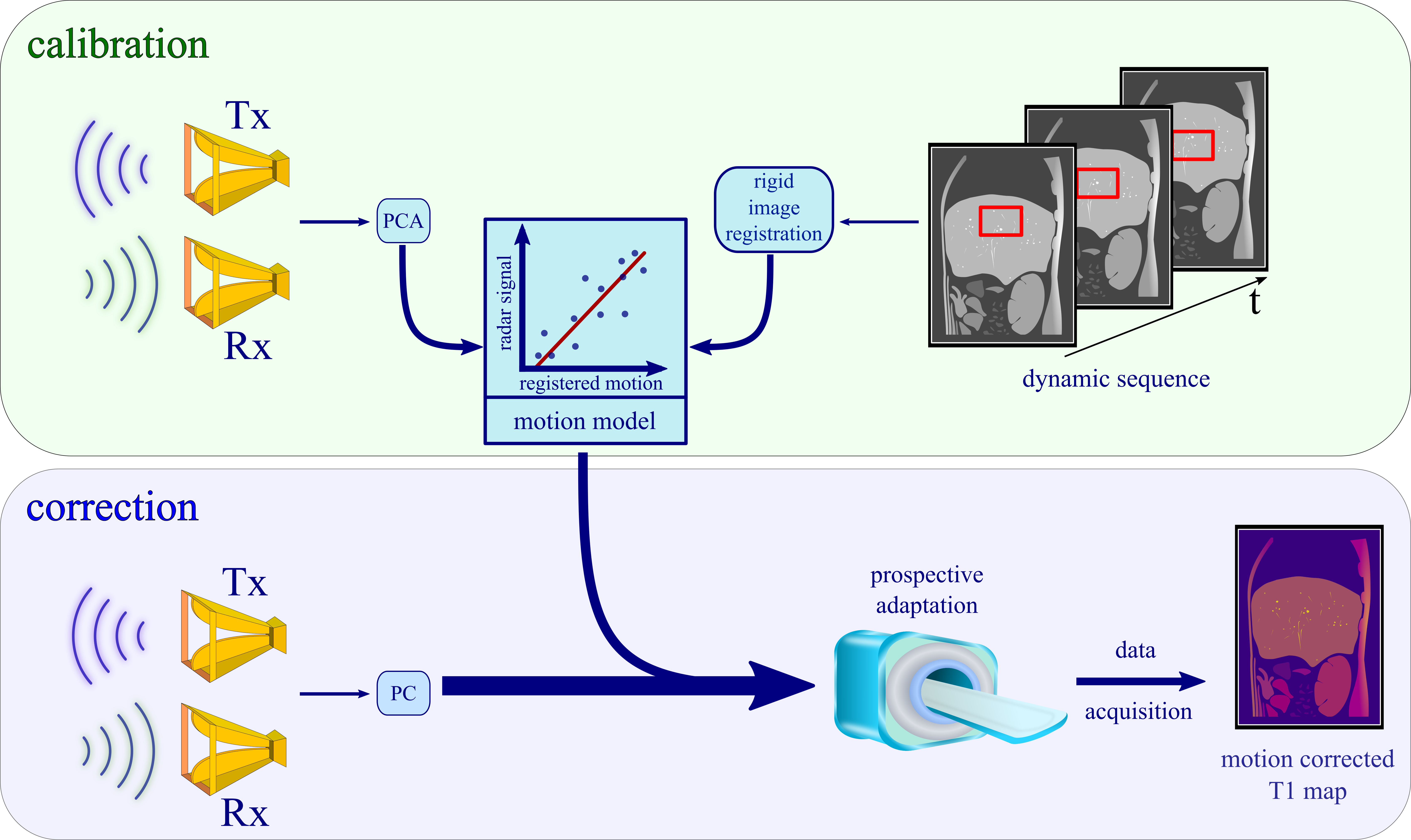
Figure 1: During calibration a radar signal and real-time MR images are recorded at the same time. The respiratory motion information from the images together with the PCA of the radar signal are fit into a linear motion model. In all subsequent scans this model is used to predict displacement from the radar response and can, therefore, correct for respiratory motion during data acquisition. There is no further image-based motion correction necessary for the T1 maps.

Figure 2: The first principal component from the radar response in time provides a respiratory motion surrogate. It is displayed against the translational displacement from a region of interest in the MR images. Over the time of 27 seconds a linear calibration model is built from both signals.
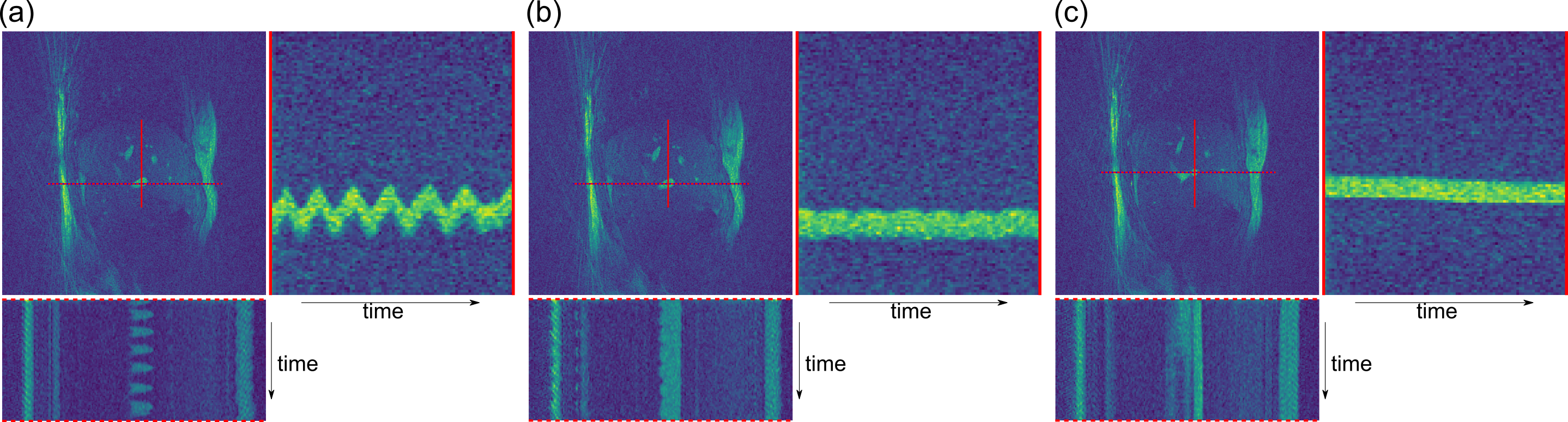
Figure 3: One frame of a real-time MR sequence and the spatial-temporal plots of a liver vessel along the AP and FH direction for (a) an uncorrected measurement, (b) a radar-based motion-corrected sequence and (c) during a breathhold. The sequence successfully adapts the slice location in the corrected case such that the position of the vessel remains constant over time. The breathhold scan shows a small spatial drift over the scan duration of 16s. All three images are obtained from different scans and hence show slightly different anatomy.
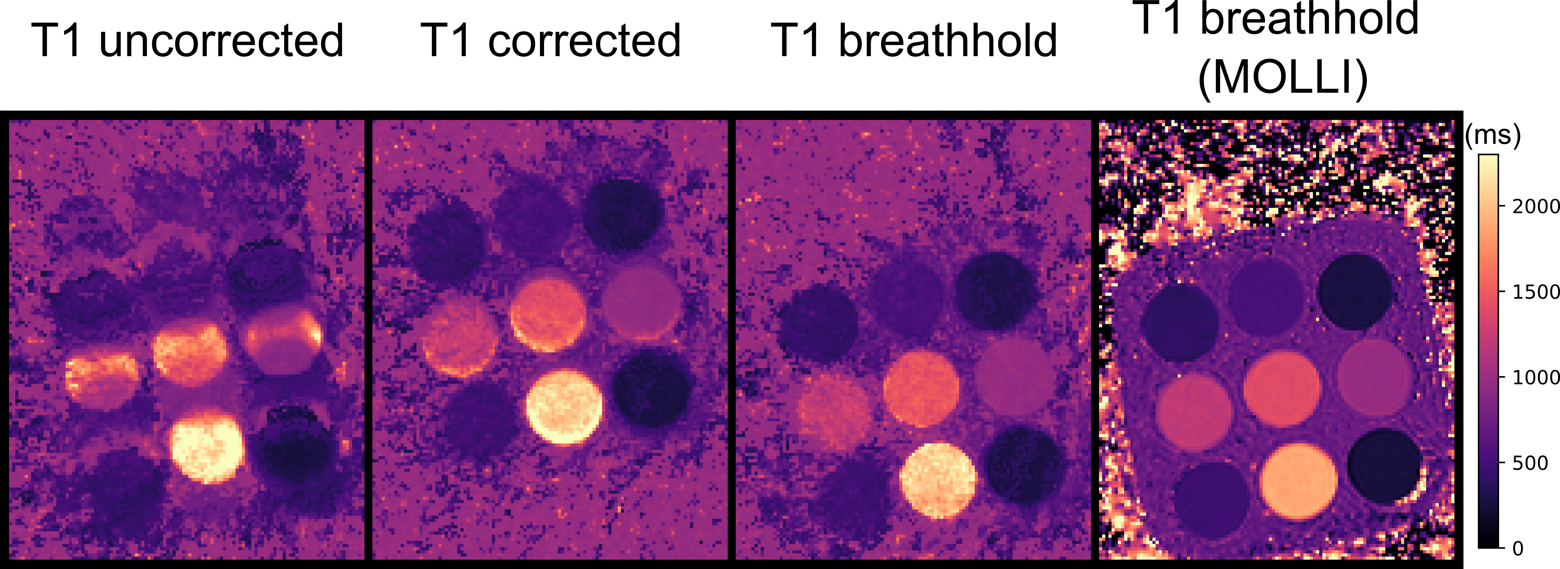
Figure 4: T1 maps of a moving T1 phantom with 9 tubes, images from left to right: uncorrected moving, radar-based motion corrected and static phantom. A T1 MOLLI scan (static) is given as reference. Displacements during the scan were properly predicted and corrected for.

Figure 5: The uncorrected T1 maps show an under-/overestimation of T1 values at the liver dome (arrows). Through-plane motion causes the underestimation in the transversal map, while overestimation as well as blurring of anatomical structures is caused by in-plane motion in the sagittal map. Both effects are strongly reduced with the proposed motion-correction scheme. Areas outside the calibrated region (e.g. kidney) were improved as well. The banding artefact in upper parts of the sagittal MOLLI scan resulted from the high sensitivity of that sequence to B0 field inhomogeneities.