0348
High Frame Rate Strain and Viscoelastic Analysis on Bovine Tibiofemoral Joints During Compression1Paul M. Rady Department of Mechanical Engineering, University of Colorado, Boulder, CO, United States, 2Biomedical Engineering Program, University of Colorado, Boulder, CO, United States
Synopsis
Osteoarthritis (OA) is a degenerative process in cartilage mainly occurring in knee. OA affects the structure and function of cartilage thus, measuring the mechanical properties of cartilage is crucial. We use spiral DENSE MRI to quantify the mechanics of intact and defected bovine articular cartilage. The samples underwent cyclic compressive load and 27 frames are captured while the joint was compressed. Displacement and strain gradually increased over time and the defected cartilage showed higher strain in the tibiofemoral contact areas. We also found creep response in the defected cartilage which may be a potential biomarker for OA detection.
INTRODUCTION:
OA is a degenerative joint disease and a severe medical and socioeconomic burden afflicting more than 10% of adults over 60 worldwide 1. Currently, OA can only be detected in the late stage using techniques like radiography since the pathogenesis of cartilage degeneration is largely unknown. Knowledge of how the mechanical properties of cartilage alter and how daily activities such as walking impact the cartilage are lacking. To address this issue, MR-based imaging methods have been advanced to investigate the structure-function relationship of soft tissue. We previously used displacement encoding with stimulated echoes (DENSE) MRI to measure in vivo cartilage deformation under compressive load 2. In an effort to enhance the temporal resolution, we explored the use of spiral scanning on DENSE MRI 3 and collected multi-frame images on intact and defected bovine joints during loading. This method allows high temporal resolution (40ms) imaging, which (unlike previous methods) facilitates the measurement of viscoelastic parameters.METHODS:
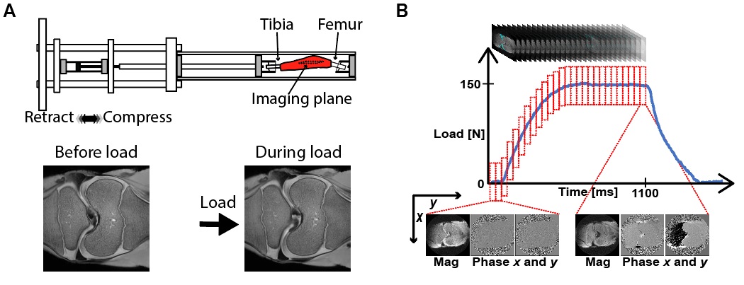
Specimen Preparation: Bovine joints (1-month-old, n=3) were obtained from an abattoir and stored in a cold room (4°c) for 48 hours. We dissected the external tissue and mounted both tibia and femur to mechanical testing grips using bone cement. The sample was placed in the compressive loading device (Fig. 1A) within a clinical MRI system (3T; Siemens Prismafit). In one intact joint, a defect (~1cm diameter) was generated on the medial condyle.Spiral DENSE MRI with Exogenous Cyclic Loading: Bovine joints underwent cyclic loading (pneumatic; 100-150N; 0.5× body weight) along the superior-inferior axis on the tibia and an ECG trigger initiated the imaging. The loading cycle was composed of compression (1s), retraction (1s) and delay (0.1s) delay before compression. The compressive load reached a plateau at t=0.52s (frame 13). Total 27 images (frames) were acquired within the loading time frame. Echo time (TE) and relaxation time (TR) were 2.5 and 20ms, respectively. Ten interleaves were used to reconstruct each image. Field of view was 125×125µm2, the number of pixels were 350×350, and the slice thickness was 1.7mm. Images were collected in the coronal plane and averaged 8 times for a high image contrast. The displacement encoding gradient was 0.32cycles/mm. Prior to image acquisition, cyclic loading was applied for 15 minutes to achieve quasi-steady-state response 4 and double echo steady state (DESS) images were collected for segmentation and to confirm that joint tissues were responding to load (Fig. 1A).
Displacement and strain calculation: Cartilage regions of interests (ROIs) were manually segmented using custom software (MATLAB) and binary masks were created to represent the articular cartilage. Displacements for each pixel within the ROIs were determined from phase data as previously described 5. Displacements then went through locally weighted scatterplot smoothing (LOWESS) filtering for 100 cycles for a span=10. Subsequently, the displacement values were used to calculate in-plane Green-Lagrange strains.
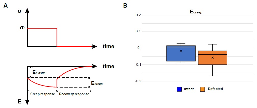
Viscoelasticity measurement: The displacement values were smoothed in time using a Gaussian filter. We fit a natural logarithm curve to the strain-time response during the constant loading time period (frame 13-27). Ecreep was calculated from the fitted curve which was defined as the normal strain Eyy at frame 13 (Eelastic) subtracted from Eyy at frame 27 (Eviscous). The analysis was conducted on the tibiofemoral contact areas for the intact joints and defected joint.
RESULTS:
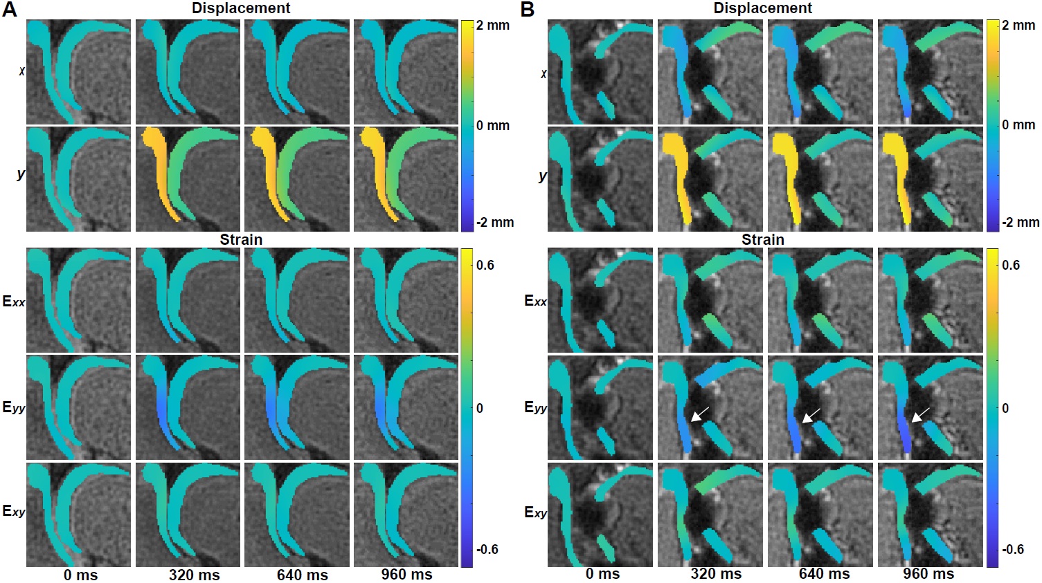
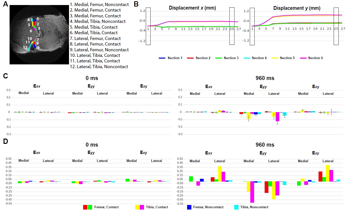
Displacement and strain maps were acquired on 27 time-lapse images during loading (Fig. 1B). Displacement and strain maps are close to 0 at t=0ms and evolve over time, demonstrating a heterogeneous pattern across cartilage on both intact and defected joints (Fig. 2). We further analyzed displacement and strain in 12 sections (Fig. 3A). All sections show a gradual increase in displacement. Displacement in y corresponding to the loading direction, overall is higher than x. Displacement y in the tibia is significantly higher than in the femur, shown as separate lines on Fig. 3B. As seen in previous work, both compression and shear occurred between the tibia and the femur 2. The tibia contact sections have the highest Eyy (-0.12) whereas the noncontact sections in the femur show minimal Eyy (-0.003) (Fig. 3C). The defected joint has higher normal and shear strain values overall compared to the intact joints. Average creep strain (Ecreep), was -0.057 on the defected joint, while the intact joint was -0.019 (Fig. 4).DISCUSSION:
This study is motivated by the hypothesis that the viscoelastic response of articular cartilage may be useful biomarkers for early OA diagnosis in addition to mechanical strain. We collect spiral DENSE MRI images during compressive loading with high temporal resolution. This approach successfully quantifies the mechanical response of cartilage under compression while the loading frequency is comparable with walking cadence. The maximum strain in the defected joint is significantly higher than the intact joint, indicating compressive load is more detrimental to defected cartilage. We also note that the viscoelastic nature of cartilage changes after damage. The viscoelasticity of cartilage may be useful for distinguishing healthy from diseased tissue 6. However, measuring viscoelasticity requires special methods regarding data acquisition in time and is challenging to apply in a clinical setting. This approach not only measures the viscoelastic response in physiologically relevant motion, but also can be utilized in in vivo settings.Acknowledgements
The authors would like to acknowledge funding from NIH R01 AR063712-08.References
1. WHO Department of Chronic Diseases and Health Promotion. Available at: http://www.who.int/chp/topics/rheumatic/en/.
2. Chan DD, Cai L, Butz KD, Trippel SB, Nauman EA, Neu CP. In vivo articular cartilage deformation: Noninvasive quantification of intratissue strain during joint contact in the human knee. Sci Rep. 2016;6:1-14.
3. Zhong X, Meyer CH, Schlesinger DJ, et al. Tracking brain motion during the cardiac cycle using spiral cine-DENSE MRI. Med Phys. 2009;36(8):3413-3419.
4. Neu CP, Hull ML. Toward an MRI-based method to measure non-uniform cartilage deformation: An MRI-cyclic loading apparatus system and steady-state cyclic displacement of articular cartilage under compressive loading. J Biomech Eng. 2003;125(2):180-188.
5. Chan DD, Neu CP. Intervertebral disc internal deformation measured by displacements under applied loading with MRI at 3T. Magn Reson Med. 2014;71(3):1231-1237.
6. Seidenstuecker M, Watrinet J, Bernstein A, et al. Viscoelasticity and histology of the human cartilage in healthy and degenerated conditions of the knee. J Orthop Surg Res. 2019;14(1):256.
Figures