0315
2D Imaging without Gradient Coils in a Low-Field Spokes-and-Hub Permanent Magnet
Irene Kuang1, Jason Stockmann2,3, Elfar Adalsteinsson1,4, and Jacob White1
1Electrical Engineering and Computer Science, Massachusetts Institute of Technology, Cambridge, MA, United States, 2A. A. Martinos Center for Biomedical Imaging, Massachusetts General Hospital, Charlestown, MA, United States, 3Harvard Medical School, Boston, MA, United States, 4Institute for Medical Engineering and Science, Massachusetts Institute of Technology, Cambridge, MA, United States
1Electrical Engineering and Computer Science, Massachusetts Institute of Technology, Cambridge, MA, United States, 2A. A. Martinos Center for Biomedical Imaging, Massachusetts General Hospital, Charlestown, MA, United States, 3Harvard Medical School, Boston, MA, United States, 4Institute for Medical Engineering and Science, Massachusetts Institute of Technology, Cambridge, MA, United States
Synopsis
We demonstrate feasibility of 2D imaging without gradient coils in a spokes-and-hub permanent magnet for a low-cost hand-held educational MR scanner. With the ease of physically assembling the imaging system in mind, the magnet was designed asymmetrically, to introduce a built-in z-gradient, and with an axis of rotation for the top magnet, so it can be tilted by either linear or rotational actuators, and generate negative or positive x-gradients. Results from simulation, Hall-effect sensor measurements, and spin echo data show that the permanent-z plus x-gradient can be used to generate orthogonal fields, and disambiguate signals from a two-tube phantom.
Introduction
The Aubert ring pair has been previously proposed as a permanent magnet topology for low-field MRI with a longitudinal B0 field that is higher than other permanent magnet arrays designs [1-4]. However, these radially polarized ring magnets are extremely difficult to cheaply manufacture with adequate uniformity. We recently presented a “spokes-and-hub” magnet topology inspired by the Aubert ring pair, but informed by the “equivalent charge” magnetic field analysis technique. As the analysis technique makes clear, the only magnet uniformity needed to generate the fields of the Aubert ring pair is the inner surfaces of the two rings, provided the outer ring is sufficiently distant. This makes it easy to assemble ring equivalents with easily-purchased bar magnets [5-7]. In this paper, we describe a method for generating gradient fields for 2D imaging using the spokes-and-hub magnet, without the use of gradient coils (Fig. 1).Methods
While past versions of our spokes-and-hub magnet have relied on an equal number of bar magnet “spokes” in each hub, we have introduced an asymmetry to the magnet hubs presented here to install a built-in gradient field. The magnet has an inner diameter of 34.4 mm, outer diameter of 85.5 mm, and contains 64 total ½ x ⅛ x 1" (12.7 x 3.175 x 25.4 mm) N42 bar magnets (B82X0, K&J Magnetics). The bar magnet spokes are distributed uniformly around both hubs, with one containing 33 magnets and the other 31 magnets to create a z-directed gradient. Simulations of the magnetic field using an equivalent-charge-based approach are shown in Fig. 2 [5]. The simulated fields in the x-z and y-z plane show the built in z-gradient (250 mT/m). To generate an x-gradient, we rely on using small mechanical tilts of one of the magnet hubs as described in [7]. Figure 3 shows simulations of an x-gradient (125 mT/m) using a +1 degree magnet tilt.Precise position control of the z-separation between magnet hubs and tilt angle is set by three linear actuators (L12-P, Actuonix Motion Devices) placed 55 mm away from the center of the magnet (Fig. 1) (though rotation about the y-axis could be accomplished with a much simpler mechanical system). Field measurements were made using 3D Linear Hall Effect sensors (ALS31300, Allegro Microsystems) attached to a 3D printer extruder. Dithered RF pulses with a 100kHz bandwidth generated by a Teensy 4.0 microcontroller were used for excitation and refocusing. Spin echoes were obtained on a single-channel, unshielded solenoid coil using a low-cost ultrasound pulser (STHV800) signal chain [6].
Results
Measured field maps are compared to the simulated fields for an x-z plane in Fig. 4. The measured fields show that the built-in z-gradient with 0 degree tilt matches simulation. Measured fields with ±1 degree tilt also match the simulated x-gradient.Figure 5 presents spin echoes with a phantom consisting of two 3 mm cylinders of water. The phantom was placed along the y-axis of the magnet and rotated in different directions to demonstrate the two gradient directions. When the cylinders are lined up along the x-axis (Fig. 5A) of the un-tilted magnet, there is a single peak in the frequency spectrum due to the uniform field along x as seen in Fig. 2. By applying a ±1 degree x-gradient tilt to the magnet, the frequency spectrum of the obtained echo shows two distinct peaks, one per cylinder of water, for the tilt in either direction (Fig. 5B). When the two cylinders are stacked along the z-gradient (Fig. 5C), there are also two peaks in the spectrum, demonstrating disambiguation along two axes.
Discussion
As seen in Figs. 4 and 5, our experimental measurements show high fidelity to the simulations in Figs. 2 and 3. Slight mismatches between simulation and measurement can be attributed to errors in linear actuator positioning and phantom placement which can be mitigated through improved position feedback control. Because of the built-in gradient along z, we only need to mechanically-tilt the magnet about one radius to be able to image in two orthogonal directions, avoiding potential heating and current constraints associated with traditional MR gradient coils. Furthermore, the physical distance needed for these tilts is much smaller (1 mm for 1 degree tilt) than the large rotations that Halbach array permanent magnets have required for spatial encoding [8,9]. This makes the spokes-and-hub imager an easy mechanical system to set up using fast and low-cost actuators.Conclusion
We have demonstrated spatial encoding using both simulation and measurement for built-in z- and small mechanical tilt x- linear gradients as proof-of-concept for 2D imaging in a low-field permanent magnet system without use of gradient coils. This magnet is easy and safe to assemble, ultra low-cost, and can be a powerful classroom educational tool with the potential to be scaled up in size to a point-of-care scanner.Acknowledgements
Funding support from NIH NIBIB R01EB018976, MIT-MGH seed grant, Skolkovo Institute of Science and Technology Next Generation Program, DoD NDSEG Fellowship, and MIT EECS department.References
- Aubert G, Cylindrical permanent magnet with longitudinal induced field, US5014032A, 1991.
- Ren ZH, Mu WC, Huang SY. Design and Optimization of a Ring-Pair Permanent Magnet Array for Head Imaging in a Low-Field Portable MRI System. IEEE Transactions on Magnetics, Vol. 55, 2019.
- Huang SY, Ren ZH, Obruchkov S, Gong J, Dykstra R, Yu W. Portable Low-Cost MRI System Based on Permanent Magnets/Magnet Arrays. iMRI, 2019.
- Hugon C, D’Amico F, Aubert G, Sakellariou D. Design of arbitrarily homogeneous permanent magnet systems for NMR and MRI: theory and experimental developments of a simple portable magnet. J. Magn. Reson. Imaging, 2010.
- Kuang I, Arango N, Stockmann J, Adalsteinsson E, White J. Equivalent-Charge-Based Optimization of Spokes-and-Hub Magnets for Hand-Held and Classroom MR Imaging. Proc. Intl. Soc. Mag. Reson. Med. 27., 2019.
- Kuang I, Arango N, Stockmann J, Adalsteinsson E, White J. Bloch-Optimized Dithered-Ultrasound-Pulse RF for Low-Field Inhomogeneous-Permanent-Magnet MR Imagers. Proc. Intl. Soc. Mag. Reson. Med. 28., 2020.
- Kuang I, Stockmann J, Adalsteinsson E, White J. Mechanical Tilt-Induced Gradient Fields for Low-Field Spokes-and-Hub MR Imagers. Proc. Intl. Soc. Mag. Reson. Med. 29., 2021.
- Cooley CZ, Stockmann JP, Armstrong BD, Sarracanie M, Lev MH, Rosen MS, Wald LL. 2D Imaging in a Lightweight Portable MRI Scanner without Gradient Coils. Magn. Res. Med., 2015.
- Cho ZH, Chung ST, Chung JY, Park SH, Kim JS, Moon CH, Hong IK. A new silent magnetic resonance imaging using a rotating DC gradient. Magn Reson Med., 1998.
Figures
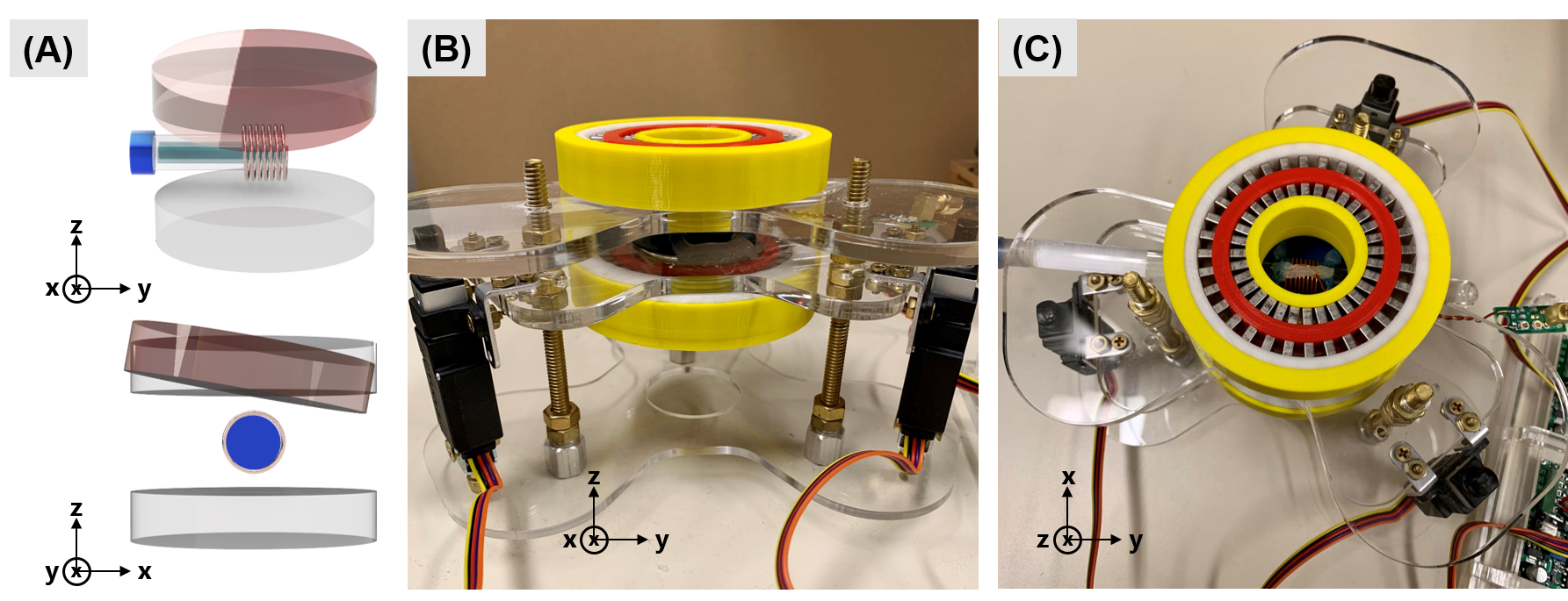
Figure 1. (A) Diagram of spokes-and-hub magnet with test tube sample and solenoid coil oriented along the y-axis. (B) Magnet held in position by linear actuators (L12-P, Actuonix). (C) View of spokes from above with test tube and solenoid at the center.
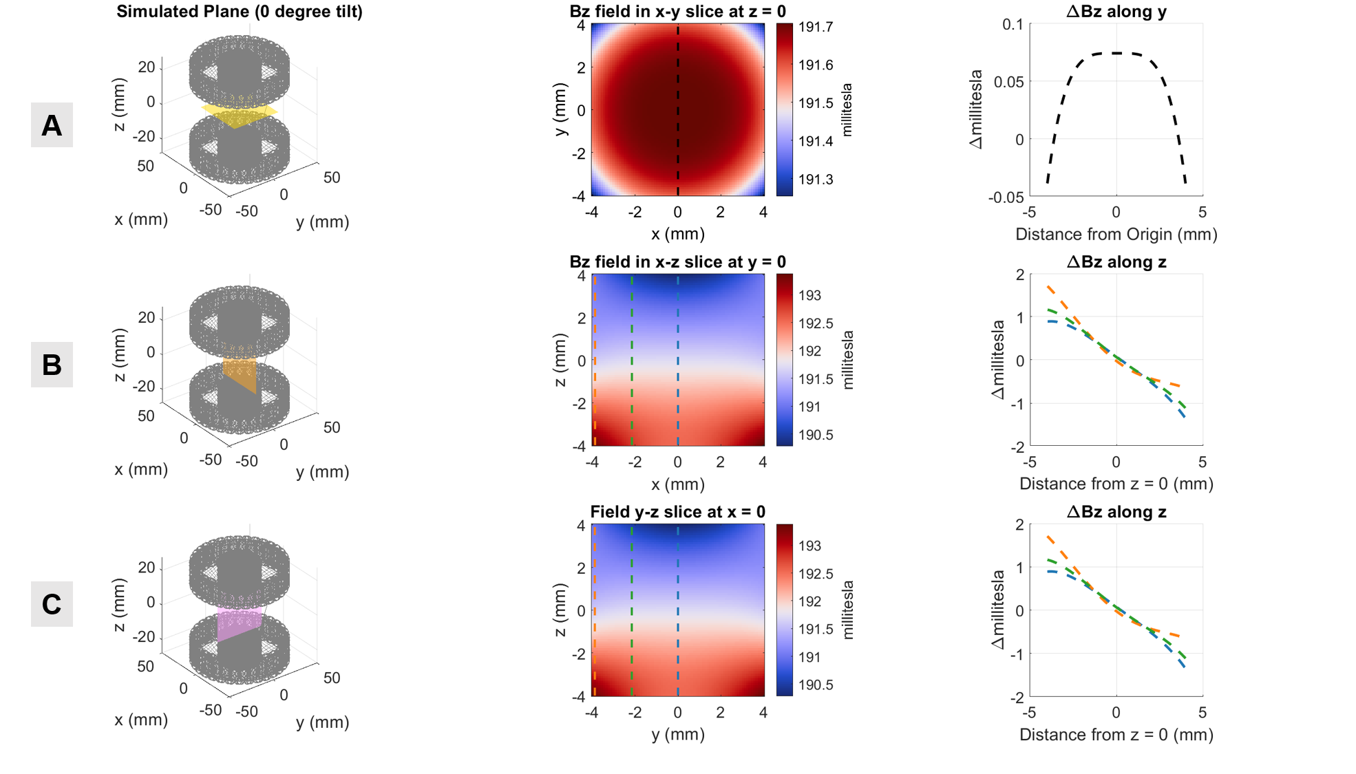
Figure 2. Simulated z-directed magnetic fields of (A) x-y slice at z=0, (B) x-z slice at y=0, and (C) y-z slice at x=0 for magnet with no tilt. The field along dotted lines in 2D field maps are plotted in the final column as ΔBz along the line. The built-in gradient along z is 250 mT/m.
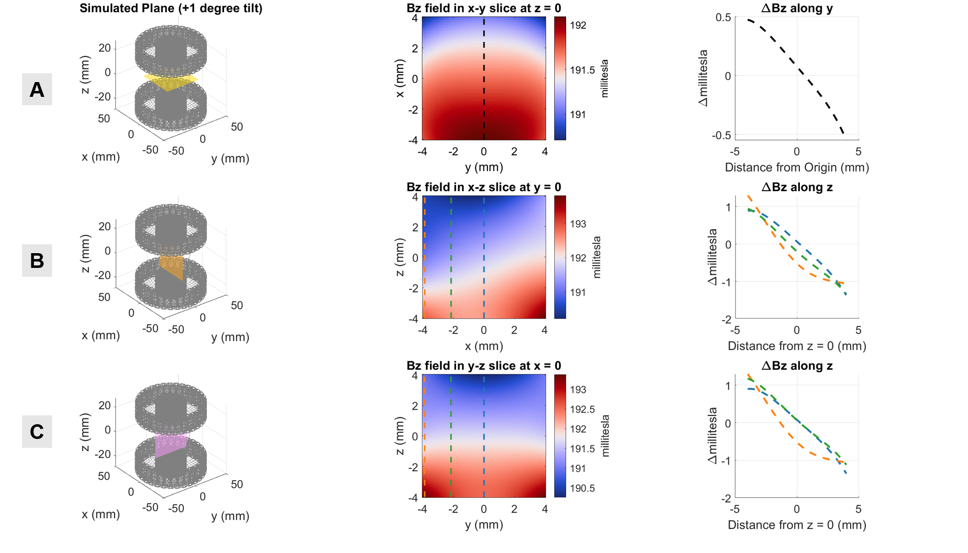
Figure 3. Simulated z-directed magnetic fields of (A) x-y slice at z=0, (B) x-z slice at y=0, and (C) y-z slice at x=0 for magnet with +1 degree mechanical tilt. The field along dotted lines in 2D field maps are plotted in the final column as ΔBz along the line. The gradient along x is 125 mT/m.
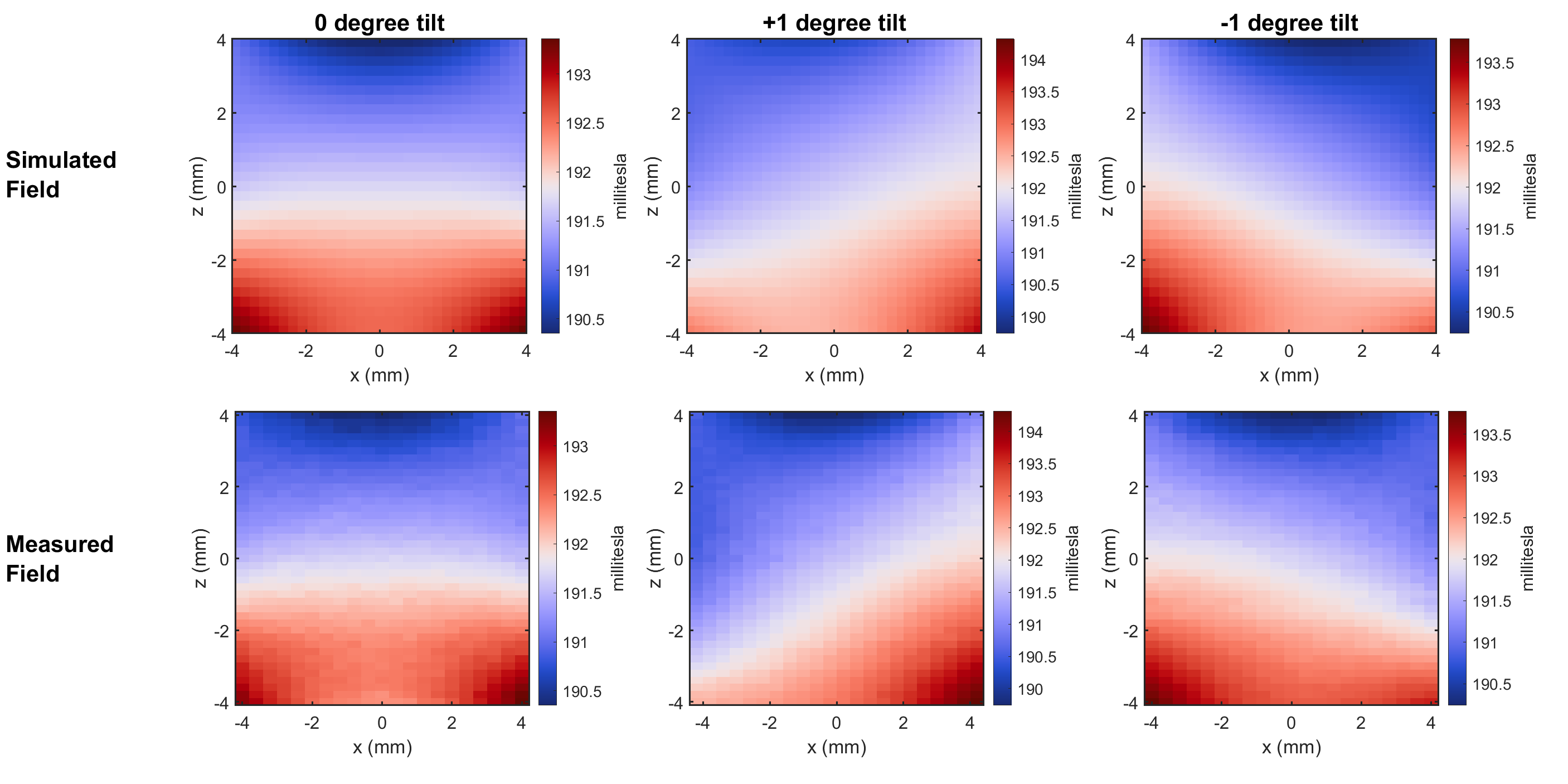
Figure 4. Simulated vs. measured Bz field maps of spokes-and-hub magnet with 0 and ±1 degree tilts. The fields were measured using an array of 3D Linear Hall Effect sensors (ALS31300, Allegro Microsystems) attached to a 3D printer extruder with 0.2mm step resolution in x and z.
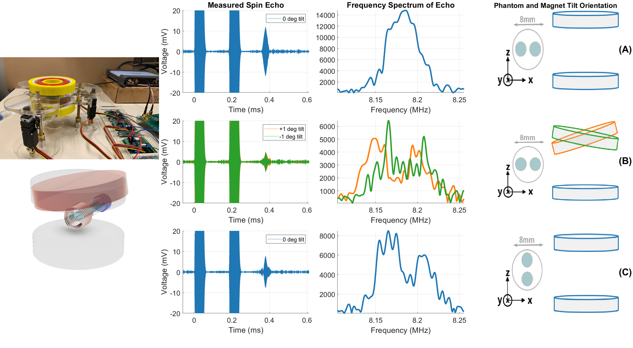
Figure 5. Measured spin echo in time and frequency for a phantom with two cylinders of water placed in various orientations along the x- and z- gradients. The time-domain echo plots show the 90° and 180° RF at 0 and 0.185ms, respectively, and TE = 0.37ms. Each cylinder of water in the phantom has 3 mm diameter and the distance from center-to-center is 4 mm. Blue lines: no mechanical x-tilt and only z-gradient. Orange and green lines: +1 and -1 degree x-tilts, respectively, with the built-in z-gradient.
DOI: https://doi.org/10.58530/2022/0315