0314
An Adaptive Target Field Framework for Complete Low Field MRI System Design
Bart de Vos1, Rob F. Remis2, and Andrew G. Webb1,2
1Leiden University Medical Center, C.J. Gorter Center for High Field MRI, Leiden, Netherlands,, Leiden, Netherlands, 2Delft University of Technology, Circuits and Systems, Delft, Netherlands, Delft, Netherlands
1Leiden University Medical Center, C.J. Gorter Center for High Field MRI, Leiden, Netherlands,, Leiden, Netherlands, 2Delft University of Technology, Circuits and Systems, Delft, Netherlands, Delft, Netherlands
Synopsis
In this work a low field point-of-care system design framework is created using target field methods for all of the hardware components. A new target field method for Halbach-based magnet optimization with variable ring diameter and spacing is derived. Magnet, gradient and RF are combined into a single framework which includes a feedback loop for dealing with the component interdependencies. The result is a pipeline which with a few user inputs can create an optimal magnet, gradient and RF design in minutes.
Introduction
Low-cost portable low field point-of-care systems can be designed for particular applications based on specific interdependent hardware requirements1-4. In this work an iterative framework including feedback is created to design the optimal Halbach-based magnet, gradient and RF coils such that a set of user-specified imaging requirements are met. In order to achieve this most efficiently we use target-field (TF) methods, which have been commonly used in gradient coil design5-10, and occasionally in RF coil design, but not in Halbach array-based permanent magnet design: a new mathematical model was derived to achieve this. Combining these methods results in a unique framework that, with minimum input, can design an entire low field MRI system within minutes.Methods
Magnet design using a TF approach: TF approaches rely on specifying the desired field (gradient, B0 or RF) within a certain region and finding an analytical relationship with respect to the source quantity.Starting from the quasi-static Maxwell’s equations an integral representation for the magnetic field in terms of a continuous cylindrical Halbach magnetization is derived. The continuous magnetization is discretized to represent individual magnets. The magnets are located within rings of variable radii and spacing. The goal is to obtain a set of ring radii r and ring spacings d such that bT – bz(r,d)=0. Here bT is the vector containing the prescribed field values inside the desired region and bz(r,d) is the vector containing the field values due to chosen radii and spacing vectors. This non-linear problem is solved using a standard Newton optimization scheme11 and constraints are applied to the radii and spacings to ensure practical solutions.
Iterative system design: The above TF approach for magnets is combined with previously derived TF methods for gradient and RF coil design5,6 to create the iterative design framework illustrated in Figure 1. Given the user inputs, a system is designed which is as compact as possible, has the strongest possible magnet and which has sufficient homogeneity for the gradient strength-dependent readout pixel bandwidth specified by the spatial resolution.
The initial guess for the field strength and number of rings is found by taking the most compact design given the minimum radius and a length/diameter ratio of 1.7 (based on previous literature). Next, power optimized gradient coils (with dimensions determined by the magnet) are designed. Using the efficiency [Tm-1A-1], the maximum current from the gradient amplifier, and the targeted resolution, the readout pixel bandwidth is compared with the blurring effect of ΔB0. If the magnet inhomogeneities dominate, the model loops back to magnet design, the target B0 is decreased by 2%, and ring diameters and separation distance are optimized to create a more homogeneous (but larger) magnet. This process is repeated until the desired spatial resolution is reached. If the user-specified minimum B0 is reached before this, additional magnet rings are added and the pipeline is restarted. If adding rings creates a magnet longer than the specified maximum, inputs such as the spatial resolution need to be relaxed. In the final step after convergence, the RF coil is designed using a uniform TF oriented in the axial direction over the ROI. The RF pulse duration must be sufficiently short to excite the entire ROI, and there is a final check that this is possible with the modelled Q value and the power available from the RF amplifier.
Results
To demonstrate the potential of the framework an adult neuroimaging system was designed. The input parameters are shown in Figure 2.For a 300 mm clear bore, the inner magnet layer diameter is set to 320 mm. The initial uniform ring spacing of 25 mm combined with a length/diameter ratio of 1.7, dictates that 23 rings constitute the initial setup. The output of the first pipeline iteration is shown in the first column of Figure 3. The B0 inhomogeneity is higher than the readout pixel bandwidth and so the magnet design iterates with B0 successively decreased in steps of 2%. The second column shows that when the minimum specified B0 (50 mT) is reached, the required magnet homogeneity is still not obtained and so additional magnet rings are added. The iterative process continues until a solution is determined with a 25-ring magnet producing a 53 mT field (third column): the magnet designs corresponding to the columns are also shown in Figure 3. Figure 4 shows the ΔB0 vs Newton iterations during the last step prior to the pipeline obtaining a solution. Figure 5 shows the final output of the framework: the gradient coils, magnet and RF coil are shown separately and combined in one assembly.
Conclusion and Discussion
A novel TF approach for Halbach-based magnet design is combined with RF and gradient coil methods, creating an integrated model which includes component interdependencies, amplifier specifications, and spatial resolution. The result is a very fast optimization framework which can be used to design an entire low field MRI system. The next step is to build in additional passive shimming to relax the homogeneity requirements of the basic magnet.Acknowledgements
Simon Stevin Meester Prize, ERC Advanced Grant 101021218 PASMARReferences
- Nakagomi M, et al. Development of a Small Car-Mounted Magnetic Resonance Imaging System for Human Elbows Using a 0.2 T Permanent Magnet. J Magn Reson (2019) 304:1–6. doi:10.1016/j.jmr.2019.04.017.
- He Y, et al. Use of 2.1 MHz MRI Scanner for Brain Imaging and its Preliminary Results in Stroke. J Magn Reson (2020) 319:106829. doi:10.1016/j.jmr.2020.106829
- O'Reilly T, et al. Three-dimensional MRI in a Homogenous 27 cm Diameter Bore Halbach Array Magnet. J Magn Reson (2019) 307:106578. doi:10.1016/j.jmr.2019.106578
- Cooley C, et al. A portable scanner for magnetic resonance imaging of the brain. Nat Biomed Eng (2020). https://doi.org/10.1038/s41551-020-00641-5.
- de Vos B, et al. Gradient Coil Design and Realization for a Halbach-Based MRI System," in IEEE Transactions on Magnetics, vol. 56, no. 3, pp. 1-8, March 2020, Art no. 5100208, doi: 10.1109/TMAG.2019.2958561.
- de Vos, et al. Design, characterisation and performance of an improved portable and sustainable low-field MRI system. Frontiers in Physics (2021). https://doi.org/10.3389/fphy.2021.701157
- Turner R. A Target Field Approach to Optimal Coil Design. J Phys D: Appl Phys (1986) 19:L147–L151. doi:10.1088/0022-3727/19/8/001
- Turner R. Minimum Inductance Coils. J Phys E Sci Instrum (1988) 21:948–52. doi:10.1088/0022-3735/21/10/008
- Forbes LK, Crozier S. A Novel Target-Field Method for Finite-Length Magnetic Resonance Shim Coils: I. Zonal Shims. J Phys D: Appl Phys (2001) 34:3447–55. doi:10.1088/0022-3727/34/24/305
- Forbes LK, Crozier S. A Novel Target-Field Method for Finite-Length Magnetic Resonance Shim Coils: II. Tesseral Shims. J Phys D: Appl Phys (2002) 35:839–49. doi:10.1088/0022-3727/35/9/303
- Nocedal, J, Wright, SJ (2006). Numerical optimization. Springer series in operations research.
Figures
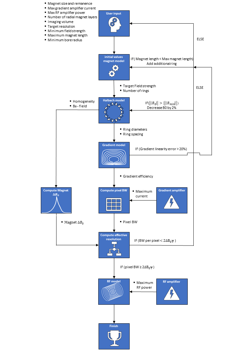
Flowchart
of the system design methodology including the feedback loop.
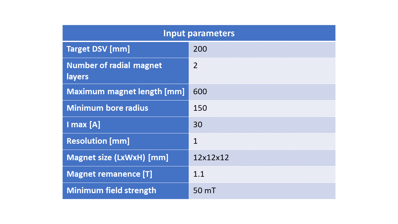
Table
containing the input parameters of the design framework for the adult size
neuroimaging example.
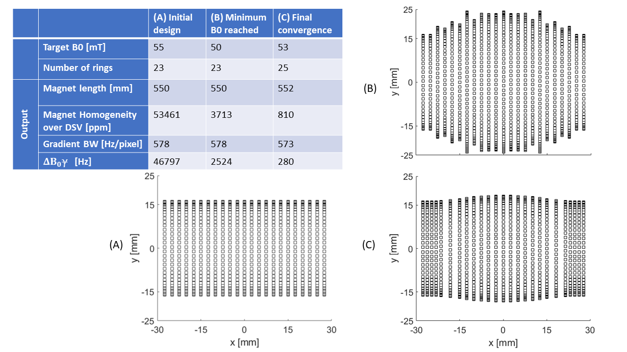
Table showing the key output parameters
for three events during the design framework: (A) the initial compact design
from which the pipeline starts the iterations. (B) the magnet design after iterating
to the user specified minimum target field strength of 50 mT. (C) The improved
design after the number of rings is increased. Right) The magnets displayed correspond to the columns (A),(B) and (C). Only the inner radial layer of magnets is shown for
clarity.
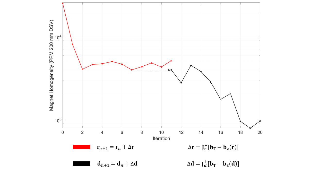
The
homogeneity in PPM per Newton iteration step for the final magnet design
discussed in the results section. The ring radii optimization is shown in red and
ring spacing in black. The Newton update scheme is shown below the figure:
Delta r/d can be calculated by taking the Moore-Penrose inverse of the Jacobian
matrix which holds the derivatives with respect to each radius/spacing for every
target point in space. This is multiplied with the target field vector minus
the system vector. The minimum and maximum ring spacing and diameter
constraints are included in this scheme.
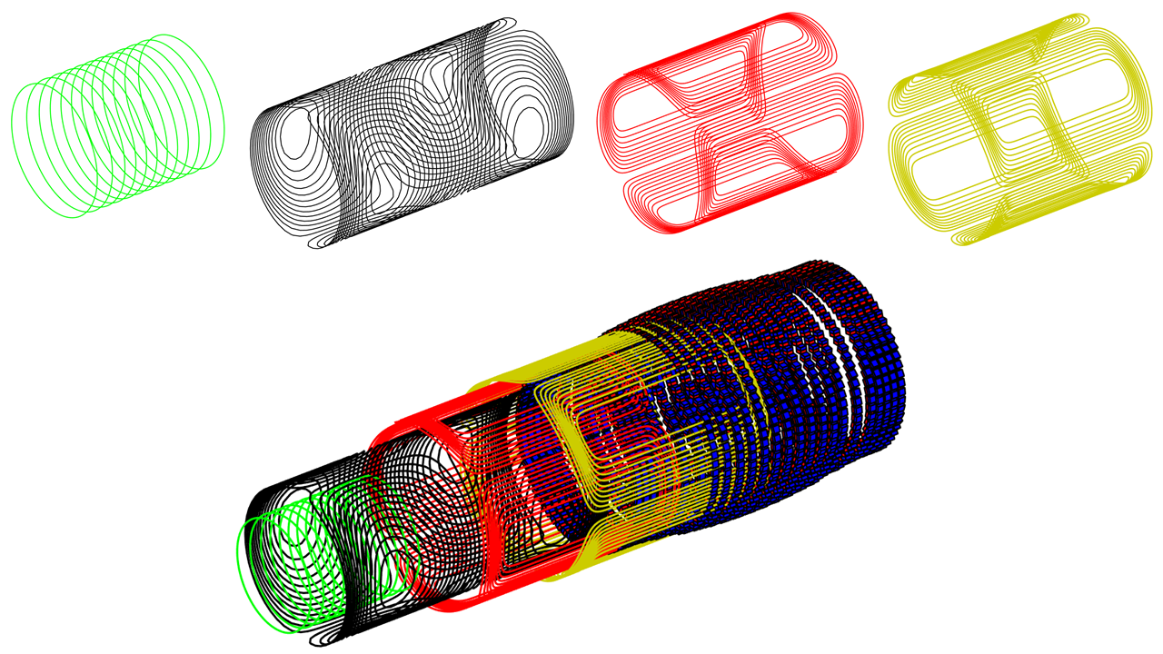
Visualization of the framework output. The gradient
coils, Magnet and RF-coil are shown separately as well as together in a
telescopic view. RF coil (green), x-gradient (black), z-gradient (red),
y-gradient (yellow), magnet (blue&red)
DOI: https://doi.org/10.58530/2022/0314