0196
Exploiting a trade-off between preamplifier noise figure and bandwidth in the design of multi-nuclear MRI detectors
Anders Nørup Thyrring Simonsen1, Vitaliy Zhurbenko1, Juan Diego Sanchez Heredia1, Wenjun Wang1, and Jan Henrik Ardenkjær-Larsen1
1Techical University of Denmark, Kgs. Lyngby, Denmark
1Techical University of Denmark, Kgs. Lyngby, Denmark
Synopsis
The perspective of extending bandwidth of an MRI detector to ~3.2MHz can enable imaging of 13C, 23Na and 129Xe nuclei with a single coil in 3T scanners. Currently, multinuclear imaging is done using bulky multi-coil setups or triple-tuned matching networks. In this work we propose a different approach to cover several nuclei frequencies by extending the bandwidth of a single receive coil manipulating impedance of the preamplifiers. A trade-off analysis of the achieved bandwidth and SNR is performed. A design example is presented. The approach promises compact and light-weight realization, which is particularly useful for ultra-flexible multinuclear receive arrays.
Introduction
There is a number of MRI applications which would benefit from being able to acquire data for several nuclei in a single imaging session1,2. For example, one could improve hyperpolarized 13C imaging using 23Na coil sensitivity profiles.Two strategies to achieve multinuclear imaging have been adopted so far1. One is to use a dedicated coil for each nucleus of interest with integrated trap circuits to prevent coil crosstalk. Another strategy is to use double- or triple-tuned matching networks in a single coil element. Both approaches to a greater or lesser extent lead to a bulky imaging setup and some degradation of SNR compared to standard single nucleus systems.
In this work we propose a different approach, which is more suitable for detecting several nuclei having similar gyromagnetic ratios. It is based on extending the bandwidth of the preamplifier decoupled detector coil at the expense of the noise figure of the preamplifier. The entire circuit is as compact as a single nucleus MRI coil, but can potentially cover 13C (32.1 MHz@3T), 23Na (33.8 MHz@3T) and 129Xe (35.3 MHz@3T) frequencies with controllable SNR tradeoff and improved decoupling levels. The approach is based on further extending the theory of preamplifier decoupling using compact matching networks3. Using this theory, the achievable bandwidth is analyzed as a function of preamplifier noise figure. A design example is shown to demonstrate the approach.
Methods
Our previous work3,4 has already indicated, that different topologies of matching and decoupling networks can result in different bandwidth of MRI receive coils. For example, for some combination of coil and preamplifier impedances, the matching/decoupling Pi-network can result in a wider bandwidth compared to T-networks even though both networks in the ideal case provide the same level of SNR and preamplifier decoupling. A schematic representation of the analyzed setup with the implemented matching/decoupling Pi-network as an example is shown in Fig. 1(a).Further extending this theory3,4, it can be shown, that the preamplifier can be noise matched to an impedance different from optimal noise impedance. This will degrade the noise figure of the preamplifier, however, at the same time, might lead to a wider SNR bandwidth. The resulting trade-off between the 1 dB SNR bandwidth and the preamplifier noise figure is shown in Fig.2.
Using the coil in Fig. 1 and a standard low noise amplifier3 at a mid-band frequency 33.7 MHz, Pi-networks can achieve a bandwidth increase by sacrificing the noise figure by a fraction of a dB. This, however, is not the case for the T-networks evaluated in this example.
One useful feature of this approach is that since the magnitude of the reflection coefficient at the input of the preamplifier is increasing with NF, the preamplifier decoupling also increases. The calculated preamplifier decoupling versus NF is shown in Fig. 3.
As can be observed in Fig. 3, the more noise figure of a preamplifier can be sacrificed, the higher the preamplifier decoupling that can be achieved. This is particularly useful in flexible receive arrays, where ensuring sufficient coil decoupling in different conformations is critical.
Results
To demonstrate the approach, the matching/decoupling network in Fig. 1(a) was designed for NFmin and NFmin+0.2 dB. The coil used is an 8 cm in diameter2 loop made of insulated 1 mm copper wire, as shown on the photo in Fig. 1(b). In case of matching to NFmin, the matching circuit elements in Fig. 1(a) are C1 = 91.1 pF, C2 = 8.9 pF and L3 = 1.7 µH. In case of matching to NFmin + 0.2dB, the designed matching circuit elements in Fig. 1(a) are C1 = 80.1 pF, C2 = 19.9 pF and L3 = 1.1 µH. The simulated SNR frequency sweep using Keysight ADS is shown in Fig. 4.(a).As can be observed, the mid-band SNR when matched to NFmin (blue curve) is 0.2 dB higher than for the NFmin+0.2 dB case (red curve), however, the bandwidth is wider for the later case. The decoupling for the NFmin+0.2 dB case is also higher, as can be seen from the simulation results presented in Fig. 4(b). The used ADS simulation setup is shown in Fig. 5.
To verify the results experimentally, the coil in Fig. 1 has been constructed and is currently being tested. The results of the measurement results will be reported at the conference.
Discussion and Conclusion
An alternative approach to design MRI detectors for multinuclear imaging is to extend the bandwidth of the single coil. This can potentially be achieved in receive coils by spoiling the Q-factor using preamplifier decoupling approach. The simulation results shown that sacrificing a small amount of preamplifier noise figure a stronger Q-factor spoiling can be achieved leading to wider bandwidth and also better decoupling.Acknowledgements
The authors would like to thank the Danish National Research Foundation (grant DNRF124) for partial support of the activities.References
- Chang-Hoon Choi, Suk-Min Hong, Jörg Felder, N. Jon Shah, “The state-of-the-art and emerging design approaches of double-tuned RF coils for X-nuclei, brain MR imaging and spectroscopy: A review,” Magnetic Resonance Imaging, Volume 72, 2020, pp. 103-116.
- Sanchez-Heredia J. D., et al, “Multi-site benchmarking of clinical 13C RF coils at 3T,” Journal of Magnetic Resonance, 2020, vol. 318, 106798.
- Wang W., Zhurbenko V., Sanchez Heredia J.D., Ardenkjær-Larsen J.H., “Three-element matching networks for receive-only MRI coil decoupling,” Magn. Reson. in Med., Volume85, Issue1, January 2021, Pages 544-550. (published online: 19 July 2020)
- Wang
W., Zhurbenko V., Sanchez Heredia J.D., Ardenkjær-Larsen J.H., “Matching and
decoupling networks for receive-only MRI arrays,” Proceedings of 14th
European Conference on Antennas and Propagation. IEEE, 2020, 4 p.
Figures
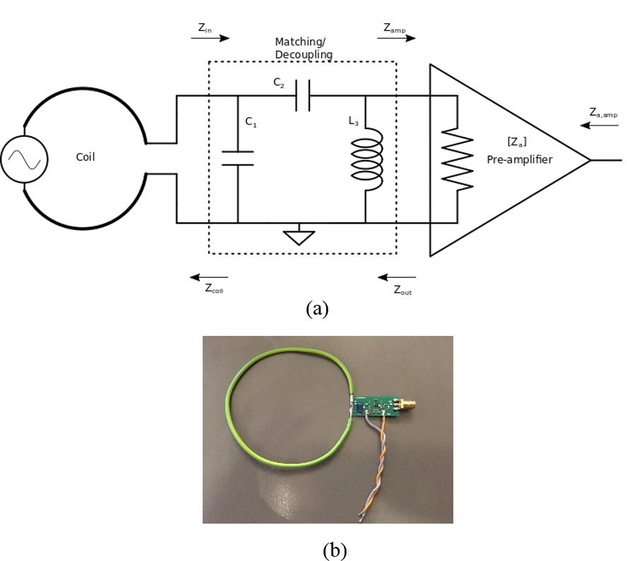
Fig.
1. Coil setup. (a) Schematic representation of the preamplifier with a matching/decoupling
Pi-network. For SNR analysis the signal is modelled as a voltage source in
series with the impedance of the coil Zcoil
≈ 0.47 + j47.1 Ω at 33.7 MHz. (b) Photograph of the implemented
8 cm diameter coil element.
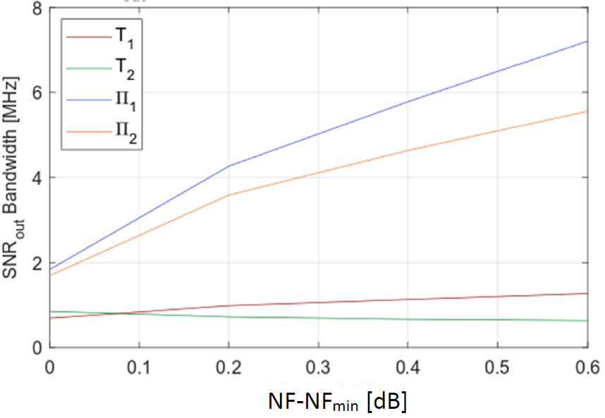
Fig. 2. 1 dB output
SNR bandwidth versus noise figure (NF) degradation (NF-NFmin) of the
preamplifier. The results are shown for all four possible solutions of the
matching/decoupling network3: two T networks and two Pi networks. The input
parameters for the analysis are the coil impedance in Fig. 1 and the
preamplifier noise and impedance parameters: Zamp and Zn,opt3.
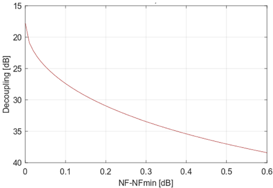
Fig. 3. Calculated maximum
decoupling of the preamplifier3 at mid-band versus noise figure. It is identical
for T- and Pi networks.
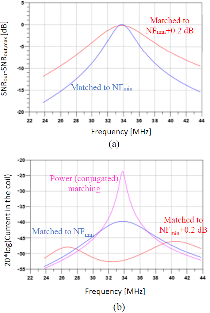
Fig. 4. Comparison
between matching to minimum noise NFmin and to NF=NFmin+0.2dB.
(a) Simulated SNR frequency sweep normalized to maximum SNR while noise matched
to NFmin (SNRout,max); (b) evaluation of the coil
decoupling properties.
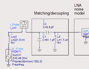
Fig. 5. Keysight ADS
simulation setup used to acquire data in Fig. 4.
DOI: https://doi.org/10.58530/2022/0196